- Table of Contents
-
- 01-Access Volume
- 00-Access Volume Organization
- 01-Ethernet Interface Configuration
- 02-Link Aggregation Configuration
- 03-Port Isolation Configuration
- 04-Service Loopback Group Configuration
- 05-DLDP Configuration
- 06-Smart Link Configuration
- 07-LLDP Configuration
- 08-VLAN Configuration
- 09-GVRP Configuration
- 10-QinQ Configuration
- 11-BPDU Tunneling Configuration
- 12-VLAN Mapping Configuration
- 13-Ethernet OAM Configuration
- 14-Connectivity Fault Detection Configuration
- 15-EPON-OLT Configuration
- 16-MSTP Configuration
- 17-RRPP Configuration
- 18-Mirroring Configuration
- Related Documents
-
| Title | Size | Download |
|---|---|---|
| 16-MSTP Configuration | 605.3 KB |
Table of Contents
Specifying the Root Bridge or a Secondary Root Bridge
Configuring the Work Mode of an MSTP Device
Configuring the Priority of the Current Device
Configuring the Maximum Hops of an MST Region
Configuring the Network Diameter of a Switched Network
Configuring the Timeout Factor
Configuring the Maximum Port Rate
Configuring Ports as Edge Ports
Setting the Type of a Connected Link to P2P
Configuring the Mode a Port Uses to Recognize/Send MSTP Packets
Enabling the Output of Port State Transition Information
Configuring the Work Mode of MSTP
Configuring the Timeout Factor
Configuring the Maximum Transmission Rate of Ports
Configuring Ports as Edge Ports
Configuring Path Costs of Ports
Setting the Type of a Connected Link to P2P
Configuring the Mode a Port Uses to Recognize/Send MSTP Packets
Enabling Output of Port State Transition Information
Configuring No Agreement Check
Configuring Protection Functions
Remotely Configuring MSTP for an ONU
Displaying and Maintaining MSTP
When configuring MSTP, go to these sections for information you are interested in:
l Configuring No Agreement Check
l Configuring Protection Functions
l Remotely Configuring MSTP for an ONU
l Displaying and Maintaining MSTP
MSTP Overview
Introduction to STP
Why STP?
The Spanning Tree Protocol (STP) was developed based on the 802.1d standard of IEEE to eliminate loops at the data link layer in a local area network (LAN). Devices running this protocol detect loops in the network by exchanging information with one another and eliminate loops by selectively blocking certain ports to prune the loop structure into a loop-free tree structure. This avoids proliferation and infinite cycling of packets that would occur in a loop network and prevents decreased performance of network devices caused by duplicate packets received.
In the narrow sense, STP refers to IEEE 802.1d STP; in the broad sense, STP refers to the IEEE 802.1d STP and various enhanced spanning tree protocols derived from that protocol.
Protocol Packets of STP
STP uses bridge protocol data units (BPDUs), also known as configuration messages, as its protocol packets.
STP-enabled network devices exchange BPDUs to establish a spanning tree. BPDUs contain sufficient information for the network devices to complete spanning tree calculation.
In STP, BPDUs come in two types:
l Configuration BPDUs, used for calculating a spanning tree and maintaining the spanning tree topology.
l Topology change notification (TCN) BPDUs, used for notifying the concerned devices of network topology changes, if any.
Basic concepts in STP
1) Root bridge
A tree network must have a root; hence the concept of root bridge was introduced in STP.
There is one and only one root bridge in the entire network, and the root bridge can change along with changes of the network topology. Therefore, the root bridge is not fixed.
After network convergence, the root bridge generates and sends out configuration BPDUs at a certain interval, and other devices just forward the BPDUs. This mechanism ensures stable topologies.
2) Root port
3) Designated bridge and designated port
The following table describes designated bridges and designated ports.
Table 1-1 Description of designated bridges and designated ports:
|
Classification |
Designated bridge |
Designated port |
|
For a device |
A device directly connected with the local device and responsible for forwarding BPDUs to the local device |
The port through which the designated bridge forwards BPDUs to this device |
|
For a LAN |
The device responsible for forwarding BPDUs to this LAN segment |
The port through which the designated bridge forwards BPDUs to this LAN segment |
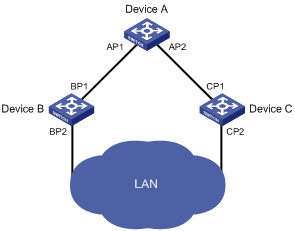
As shown in Path cost, AP1 and AP2, BP1 and BP2, and CP1 and CP2 are ports on Device A, Device B, and Device C respectively.
l If Device A forwards BPDUs to Device B through AP1, the designated bridge for Device B is Device A, and the designated port of Device B is port AP1 on Device A.
l Two devices are connected to the LAN: Device B and Device C. If Device B forwards BPDUs to the LAN, the designated bridge for the LAN is Device B, and the designated port for the LAN is the port BP2 on Device B.
Figure 1-1 A schematic diagram of designated bridges and designated ports
Path cost
Path cost is a reference value used for link selection in STP. By calculating path costs, STP selects relatively robust links and blocks redundant links, and finally prunes the network into a loop-free tree.
![]()
All the ports on the root bridge are designated ports.
How STP works
The devices on a network exchange BPDUs to identify the network topology. Configuration BPDUs contain sufficient information for the network devices to complete spanning tree calculation. Important fields in a configuration BPDU include:
l Root bridge ID: consisting of the priority and MAC address of the root bridge.
l Root path cost: the cost of the path to the root bridge.
l Designated bridge ID: consisting of the priority and MAC address of the designated bridge.
l Designated port ID: designated port priority plus port name.
l Message age: age of the configuration BPDU while it propagates in the network.
l Max age: maximum age of the configuration BPDU.
l Hello time: configuration BPDU interval.
l Forward delay: the delay used by STP bridges to transit the state of the root and designated ports to forwarding.
![]()
For simplicity, the descriptions and examples below involve only four fields of configuration BPDUs:
l Root bridge ID (represented by device priority)
l Root path cost (related to the rate of the link connected to the port)
l Designated bridge ID (represented by device priority)
l Designated port ID (represented by port name)
Calculation process of the STP algorithm
1) Initial state
2) Selection of the optimum configuration BPDU
Each device sends out its configuration BPDU and receives configuration BPDUs from other devices.
The process of selecting the optimum configuration BPDU is as follows:
Table 1-2 Selection of the optimum configuration BPDU
|
Step |
Actions |
|
1 |
Upon receiving a configuration BPDU on a port, the device performs the following: l If the received configuration BPDU has a lower priority than that of the configuration BPDU generated by the port, the device discards the received configuration BPDU and does not process the configuration BPDU of this port. l If the received configuration BPDU has a higher priority than that of the configuration BPDU generated by the port, the device replaces the content of the configuration BPDU generated by the port with the content of the received configuration BPDU. |
|
2 |
The device compares the configuration BPDUs of all the ports and chooses the optimum configuration BPDU. |
![]()
The following are the principles of configuration BPDU comparison:
l The configuration BPDU that has the lowest root bridge ID has the highest priority.
l If all the configuration BPDUs have the same root bridge ID, their root path costs are compared. Assume that the root path cost in a configuration BPDU plus the path cost of a receiving port is S. The configuration BPDU with the smallest S value has the highest priority.
l If all configuration BPDUs have the same ports value, their designated bridge IDs, designated port IDs, and the IDs of the receiving ports are compared in sequence. The configuration BPDU containing a smaller ID wins out.
3) Selection of the root bridge
Initially, each STP-enabled device on the network assumes itself to be the root bridge, with the root bridge ID being its own device ID. By exchanging configuration BPDUs, the devices compare their root bridge IDs to elect the device with the smallest root bridge ID as the root bridge.
4) Selection of the root port and designated ports on a non-root device
The process of selecting the root port and designated ports is as follows:
Table 1-3 Selection of the root port and designated ports
|
Step |
Description |
|
1 |
A non-root-bridge device regards the port on which it received the optimum configuration BPDU as the root port. |
|
2 |
Based on the configuration BPDU and the path cost of the root port, the device calculates a designated port configuration BPDU for each of the rest ports. l The root bridge ID is replaced with that of the configuration BPDU of the root port. l The root path cost is replaced with that of the configuration BPDU of the root port plus the path cost of the root port. l The designated bridge ID is replaced with the ID of this device. l The designated port ID is replaced with the ID of this port. |
|
3 |
The device compares the calculated configuration BPDU with the configuration BPDU on the port of which the port role is to be defined, and acts depending on the comparison result: l If the calculated configuration BPDU is superior, the device considers this port as the designated port, and replaces the configuration BPDU on the port with the calculated configuration BPDU, which will be sent out periodically. l If the configuration BPDU on the port is superior, the device blocks this port without updating its configuration BPDU. The blocked port can receive BPDUs but not send BPDUs or forward data. |
![]()
When the network topology is stable, only the root port and designated ports forward traffic, while other ports are all in the blocked state – they receive BPDUs but do not forward BPDUs or user traffic.
A tree-shape topology forms upon successful election of the root bridge, the root port on each non-root bridge and the designated ports.
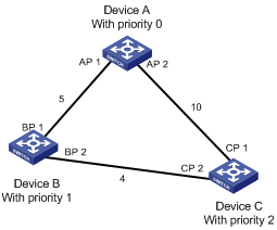
The following is an example of how the STP algorithm works. As shown in Figure 1-2, assume that the priority of Device A is 0, the priority of Device B is 1, the priority of Device C is 2, and the path costs of these links are 5, 10 and 4 respectively.
Figure 1-2 Network diagram for the STP algorithm
l Initial state of each device
The following table shows the initial state of each device.
Table 1-4 Initial state of each device
|
Device |
Port name |
BPDU of port |
|
Device A |
AP1 |
{0, 0, 0, AP1} |
|
AP2 |
{0, 0, 0, AP2} |
|
|
Device B |
BP1 |
{1, 0, 1, BP1} |
|
BP2 |
{1, 0, 1, BP2} |
|
|
Device C |
CP1 |
{2, 0, 2, CP1} |
|
CP2 |
{2, 0, 2, CP2} |
l Comparison process and result on each device
The following table shows the comparison process and result on each device.
Table 1-5 Comparison process and result on each device
|
Device |
Comparison process |
BPDU of port after comparison |
|
Device A |
l Port AP1 receives the configuration BPDU of Device B {1, 0, 1, BP1}. Device A finds that the configuration BPDU of the local port {0, 0, 0, AP1} is superior to the received configuration BPDU, and therefore discards the received configuration BPDU. l Port AP2 receives the configuration BPDU of Device C {2, 0, 2, CP1}. Device A finds that the BPDU of the local port {0, 0, 0, AP2} is superior to the received configuration BPDU, and therefore discards the received configuration BPDU. l Device A finds that both the root bridge and designated bridge in the configuration BPDUs of all its ports are itself, so it assumes itself to be the root bridge. In this case, it does not make any change to the configuration BPDU of each port, and starts sending out configuration BPDUs periodically. |
AP1: {0, 0, 0, AP1} AP2: {0, 0, 0, AP2} |
|
Device B |
l Port BP1 receives the configuration BPDU of Device A {0, 0, 0, AP1}. Device B finds that the received configuration BPDU is superior to the configuration BPDU of the local port {1, 0, 1, BP1}, and updates the configuration BPDU of BP1. l Port BP2 receives the configuration BPDU of Device C {2, 0, 2, CP2}. Device B finds that the configuration BPDU of the local port {1, 0, 1, BP2} is superior to the received configuration BPDU, and therefore discards the received configuration BPDU. |
BP1: {0, 0, 0, AP1} BP2: {1, 0, 1, BP2} |
|
l Device B compares the configuration BPDUs of all its ports, and determines that the configuration BPDU of BP1 is the optimum configuration BPDU. Then, it uses BP1 as the root port, the configuration BPDUs of which will not be changed. l Based on the configuration BPDU of BP1 and the path cost of the root port (5), Device B calculates a designated port configuration BPDU for BP2 {0, 5, 1, BP2}. l Device B compares the calculated configuration BPDU {0, 5, 1, BP2} with the configuration BPDU of BP2. If the calculated BPDU is superior, BP2 will act as the designated port, and the configuration BPDU on this port will be replaced with the calculated configuration BPDU, which will be sent out periodically. |
Root port BP1: {0, 0, 0, AP1} Designated port BP2: {0, 5, 1, BP2} |
|
|
Device C |
l Port CP1 receives the configuration BPDU of Device A {0, 0, 0, AP2}. Device C finds that the received configuration BPDU is superior to the configuration BPDU of the local port {2, 0, 2, CP1}, and updates the configuration BPDU of CP1. l Port CP2 receives the configuration BPDU of port BP2 of Device B {1, 0, 1, BP2} before the configuration BPDU is updated. Device C finds that the received configuration BPDU is superior to the configuration BPDU of the local port {2, 0, 2, CP2}, and therefore updates the configuration BPDU of CP2. |
CP1: {0, 0, 0, AP2} CP2: {1, 0, 1, BP2} |
|
After comparison: l The configuration BPDU of CP1 is elected as the optimum configuration BPDU, so CP1 is identified as the root port, the configuration BPDUs of which will not be changed. l Device C compares the calculated designated port configuration BPDU {0, 10, 2, CP2} with the configuration BPDU of CP2, and CP2 becomes the designated port, and the configuration BPDU of this port will be replaced with the calculated configuration BPDU. |
Root port CP1: {0, 0, 0, AP2} Designated port CP2: {0, 10, 2, CP2} |
|
|
l Then, port CP2 receives the updated configuration BPDU of Device B {0, 5, 1, BP2}. Because the received configuration BPDU is superior to its own configuration BPDU, Device C launches a BPDU update process. l At the same time, port CP1 receives periodic configuration BPDUs from Device A. Device C does not launch an update process after comparison. |
CP1: {0, 0, 0, AP2} CP2: {0, 5, 1, BP2} |
|
|
After comparison: l Because the root path cost of CP2 (9) (root path cost of the BPDU (5) plus path cost corresponding to CP2 (4)) is smaller than the root path cost of CP1 (10) (root path cost of the BPDU (0) + path cost corresponding to CP2 (10)), the BPDU of CP2 is elected as the optimum BPDU, and CP2 is elected as the root port, the messages of which will not be changed. l After comparison between the configuration BPDU of CP1 and the calculated designated port configuration BPDU, port CP1 is blocked, with the configuration BPDU of the port unchanged, and the port will not receive data from Device A until a spanning tree calculation process is triggered by a new event, for example, the link from Device B to Device C going down. |
Blocked port CP2: {0, 0, 0, AP2} Root port CP2: {0, 5, 1, BP2} |
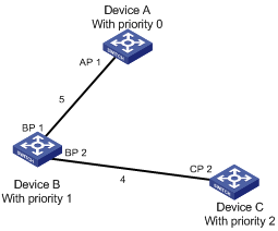
After the comparison processes described in the table above, a spanning tree with Device A as the root bridge is established as shown in Figure 1-3.
Figure 1-3 The final calculated spanning tree
![]()
The spanning tree calculation process in this example is only simplified process.
The BPDU forwarding mechanism in STP
l Upon network initiation, every switch regards itself as the root bridge, generates configuration BPDUs with itself as the root, and sends the configuration BPDUs at a regular hello interval.
l If it is the root port that received a configuration BPDU and the received configuration BPDU is superior to the configuration BPDU of the port, the device increases the message age carried in the configuration BPDU following a certain rule and starts a timer to time the configuration BPDU while sending out this configuration BPDU through the designated port.
l If the configuration BPDU received on a designated port has a lower priority than the configuration BPDU of the local port, the port immediately sends out its own configuration BPDU in response.
l If a path becomes faulty, the root port on this path will no longer receive new configuration BPDUs and the old configuration BPDUs will be discarded due to timeout. In this case, the device will generate a configuration BPDU with itself as the root and send out the BPDUs and TCN BPDUs. This triggers a new spanning tree calculation process to establish a new path to restore the network connectivity.
However, the newly calculated configuration BPDU will not be propagated throughout the network immediately, so the old root ports and designated ports that have not detected the topology change continue forwarding data along the old path. If the new root ports and designated ports begin to forward data as soon as they are elected, a temporary loop may occur.
STP timers
STP calculation involves three important timing parameters: forward delay, hello time, and max age.
l Forward delay is the delay time for device state transition.
A path failure can cause spanning tree re-calculation to adapt the spanning tree structure to the change. However, the resulting new configuration BPDU cannot propagate throughout the network immediately. If the newly elected root ports and designated ports start to forward data right away, a temporary loop is likely to occur.
For this reason, as a mechanism for state transition in STP, the newly elected root ports or designated ports require twice the forward delay time before transiting to the forwarding state to ensure that the new configuration BPDU has propagated throughout the network.
l Hello time is the time interval at which a device sends hello packets to the surrounding devices to ensure that the paths are fault-free.
l Max age is a parameter used to determine whether a configuration BPDU held by the device has expired. A configuration BPDU beyond the max age will be discarded.
Introduction to MSTP
Why MSTP
1) Weakness of STP and RSTP
STP does not support rapid state transition of ports. A newly elected root port or designated port must wait twice the forward delay time before transiting to the forwarding state, even if it is a port on a point-to-point link or an edge port, which directly connects to a user terminal rather than to another device or a shared LAN segment.
The Rapid Spanning Tree Protocol (RSTP) is an optimized version of STP. RSTP allows a newly elected root port or designated port to enter the forwarding state much quicker under certain conditions than in STP. As a result, it takes a shorter time for the network to converge.
![]()
l In RSTP, a newly elected root port can enter the forwarding state rapidly if this condition is met: The old root port on the device has stopped forwarding data and the upstream designated port has started forwarding data.
l In RSTP, a newly elected designated port can enter the forwarding state rapidly if this condition is met: The designated port is an edge port or a port connected with a point-to-point link. If the designated port is an edge port, it can enter the forwarding state directly; if the designated port is connected with a point-to-point link, it can enter the forwarding state immediately after the device undergoes handshake with the downstream device and gets a response.
Although RSTP supports rapid network convergence, it has the same drawback as STP does: All bridges within a LAN share the same spanning tree, so redundant links cannot be blocked based on VLAN, and the packets of all VLANs are forwarded along the same spanning tree.
2) Features of MSTP
The Multiple Spanning Tree Protocol (MSTP) overcomes the shortcomings of STP and RSTP. In addition to the support for rapid network convergence, it also allows data flows of different VLANs to be forwarded along separate paths, thus providing a better load sharing mechanism for redundant links. For description about VLANs, refer to VLAN Configuration in the Access Volume.
MSTP features the following:
l MSTP supports mapping VLANs to MST instances (MSTIs) by means of a VLAN-to-MSTI mapping table. MSTP can reduce communication overheads and resource usage by mapping multiple VLANs to one MSTI.
l MSTP divides a switched network into multiple regions, each containing multiple spanning trees that are independent of one another.
l MSTP prunes a loop network into a loop-free tree, thus avoiding proliferation and endless cycling of packets in a loop network. In addition, it provides multiple redundant paths for data forwarding, thus supporting load balancing of VLAN data.
l MSTP is compatible with STP and RSTP.
Basic concepts in MSTP
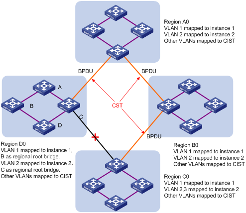
Assume that all the four switches in Figure 1-4 are running MSTP. This section explains some basic concepts of MSTP based on the figure.
Figure 1-4 Basic concepts in MSTP
1) MST region
A multiple spanning tree region (MST region) consists of multiple devices in a switched network and the network segments among them. These devices have the following characteristics:
l All are MSTP-enabled,
l They have the same region name,
l They have the same VLAN-to-MSTI mapping configuration,
l They have the same MSTP revision level configuration, and
l They are physically linked with one another.
For example, all the devices in region A0 in Figure 1-4 have the same MST region configuration:
l The same region name,
l The same VLAN-to-MSTI mapping configuration (VLAN 1 is mapped to MSTI 1, VLAN 2 to MSTI 2, and the rest to the common and internal spanning tree (CIST, that is, MSTI 0), and
l The same MSTP revision level (not shown in the figure).
Multiple MST regions can exist in a switched network. You can use an MSTP command to assign multiple devices to the same MST region.
2) VLAN-to-MSTI mapping table
As an attribute of an MST region, the VLAN-to-MSTI mapping table describes the mapping relationships between VLANs and MSTIs. In Figure 1-4, for example, the VLAN-to-MSTI mapping table of region A0 describes that the same region name, the same VLAN-to-MSTI mapping configuration (VLAN 1 is mapped to MSTI 1, VLAN 2 to MSTI 2, and the rest to CIST). MSTP achieves load balancing by means of the VLAN-to-MSTI mapping table.
3) IST
An internal spanning tree (IST) is a spanning tree that runs in an MST region.
ISTs in all MST regions and the common spanning tree (CST) jointly constitute the common and internal spanning tree (CIST) of the entire network. An IST is a section of the CIST.
In Figure 1-4, for example, the CIST has a section in each MST region, and this section is the IST in the respective MST region.
4) CST
The CST is a single spanning tree that connects all MST regions in a switched network. If you regard each MST region as a “device”, the CST is a spanning tree calculated by these devices through STP or RSTP. For example, the red lines in Figure 1-4 represent the CST.
5) CIST
Jointly constituted by ISTs and the CST, the CIST is a single spanning tree that connects all devices in a switched network.
In Figure 1-4, for example, the ISTs in all MST regions plus the inter-region CST constitute the CIST of the entire network.
6) MSTI
Multiple spanning trees can be generated in an MST region through MSTP, one spanning tree being independent of another. Each spanning tree is referred to as a multiple spanning tree instance (MSTI). In Figure 1-4, for example, multiple spanning trees can exist in each MST region, each spanning tree corresponding to a VLAN. These spanning trees are called MSTIs.
7) Regional root bridge
The root bridge of the IST or an MSTI within an MST region is the regional root bridge of the IST or the MSTI. Based on the topology, different spanning trees in an MST region may have different regional roots.
For example, in region D0 in Figure 1-4, the regional root of MSTI 1 is device B, while that of MSTI 2 is device C.
8) Common root bridge
The common root bridge is the root bridge of the CIST.
In Figure 1-4, for example, the common root bridge is a device in region A0.
9) Boundary port
A boundary port is a port that connects an MST region to another MST region, or to a single spanning-tree region running STP, or to a single spanning-tree region running RSTP. In Figure 1-4, for example, if a device in region A0 is interconnected with the first port of a device in region D0 and the common root bridge of the entire switched network is located in region A0, the first port of that device in region D0 is the boundary port of region D0.
During MSTP calculation, a boundary port’s role on an MSTI is consistent with its role on the CIST. But that is not true with master ports. A master port in MSTIs is a root port in the CIST.
10) Roles of ports
MSTP calculation involves these port roles: root port, designated port, master port, alternate port, backup port, and so on.
l Root port: a port responsible for forwarding data to the root bridge.
l Designated port: a port responsible for forwarding data to the downstream network segment or device.
l Master port: A port on the shortest path from the current region to the common root bridge, connecting the MST region to the common root bridge. If the region is seen as a node, the master port is the root port of the region on the CST. The master port is a root port on IST/CIST and still a master port on the other MSTIs.
l Alternate port: The standby port for the root port and the master port. When the root port or master port is blocked, the alternate port becomes the new root port or master port.
l Backup port: The backup port of a designated port. When the designated port is blocked, the backup port becomes a new designated port and starts forwarding data without delay. A loop occurs when two ports of the same MSTP device are interconnected. Therefore, the device will block either of the two ports, and the backup port is that port to be blocked.
A port can play different roles in different MSTIs.
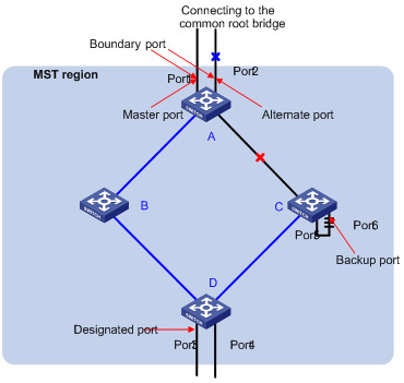
Figure 1-5 helps understand these concepts. In this figure:
l Devices A, B, C, and D constitute an MST region.
l Port 1 and port 2 of device A connect to the common root bridge.
l Port 5 and port 6 of device C form a loop.
l Port 3 and port 4 of device D connect downstream to other MST regions.
11) Port states
In MSTP, port states fall into the following three:
l Forwarding: the port learns MAC addresses and forwards user traffic;
l Learning: the port learns MAC addresses but does not forward user traffic;
l Discarding: the port neither learns MAC addresses nor forwards user traffic.
![]()
When in different MSTIs, a port can be in different states.
A port state is not exclusively associated with a port role. Table 1-6 lists the port state(s) supported by each port role (“√” indicates that the port supports this state, while “—“ indicates that the port does not support this state).
Table 1-6 Ports states supported by different port roles
|
Port role (right) |
Root port/master port |
Designated port |
Alternate port |
Backup port |
|
Port state (below) |
||||
|
Forwarding |
√ |
√ |
— |
— |
|
Learning |
√ |
√ |
— |
— |
|
Discarding |
√ |
√ |
√ |
√ |
How MSTP works
MSTP divides an entire Layer 2 network into multiple MST regions, which are interconnected by a calculated CST. Inside an MST region, multiple spanning trees are calculated, each being called an MSTI. Among these MSTIs, MSTI 0 is the IST, while all the others are MSTIs. Similar to STP, MSTP uses configuration BPDUs to calculate spanning trees. The only difference between the two protocols is that an MSTP BPDU carries the MSTP configuration on the device from which this BPDU is sent.
1) CIST calculation
The calculation of a CIST tree is also the process of configuration BPDU comparison. During this process, the device with the highest priority is elected as the root bridge of the CIST. MSTP generates an IST within each MST region through calculation, and, at the same time, MSTP regards each MST region as a single device and generates a CST among these MST regions through calculation. The CST and ISTs constitute the CIST of the entire network.
2) MSTI calculation
Within an MST region, MSTP generates different MSTIs for different VLANs based on the VLAN-to-MSTI mappings. MSTP performs a separate calculation process, which is similar to spanning tree calculation in STP, for each spanning tree. For details, refer to How STP works.
In MSTP, a VLAN packet is forwarded along the following paths:
l Within an MST region, the packet is forwarded along the corresponding MSTI.
l Between two MST regions, the packet is forwarded along the CST.
Implementation of MSTP on devices
MSTP is compatible with STP and RSTP. STP and RSTP protocol packets can be recognized by devices running MSTP and used for spanning tree calculation.
In addition to basic MSTP functions, many special functions are provided for ease of management, as follows:
l Root bridge hold
l Root bridge backup
l Root guard
l BPDU guard
l TC-BPDU guard
l Support for hot swapping of interface cards and active/standby changeover.
Protocols and Standards
MSTP is documented in:
l IEEE 802.1d: Spanning Tree Protocol
l IEEE 802.1w: Rapid Spanning Tree Protocol
l IEEE 802.1s: Multiple Spanning Tree Protocol
Configuration Task List
Before configuring MSTP, you need to know the position of each device in each MSTI: root bridge or leave node. In each MSTI, one, and only one device acts as the root bridge, while all others as leaf nodes.
Complete these tasks to configure MSTP:
|
Task |
Remarks |
|
|
Required |
||
|
Optional |
||
|
Optional |
||
|
Optional |
||
|
Optional |
||
|
Optional |
||
|
Optional |
||
|
Optional |
||
|
Optional |
||
|
Optional |
||
|
Optional |
||
|
Configuring the Mode a Port Uses to Recognize/Send MSTP Packets |
Optional |
|
|
Optional |
||
|
Required |
||
|
Required |
||
|
Optional |
||
|
Optional |
||
|
Optional |
||
|
Optional |
||
|
Optional |
||
|
Optional |
||
|
Optional |
||
|
Configuring the Mode a Port Uses to Recognize/Send MSTP Packets |
Optional |
|
|
Optional |
||
|
Required |
||
|
Optional |
||
|
Optional |
||
|
Optional |
||
|
Optional |
||
![]()
l If both GVRP and MSTP are enabled on a device at the same time, GVRP packets will be forwarded along the CIST. Therefore, if you wish to advertise a certain VLAN within the network through GVRP in this case, make sure that this VLAN is mapped to the CIST (MSTI 0) when configuring the VLAN-to-MSTI mapping table. For the detailed information of GVRP, refer to GVRP Configuration of the Access Volume.
l MSTP is mutually exclusive with any of the following functions on a port: service loopback, RRPP, Smart Link, and BPDU tunnel.
l Configurations made in Layer-2 aggregate port view can take effect only on the aggregate port; configurations made on an aggregation member port can take effect only after the port is removed from the aggregation group. For detailed information about link aggregation, refer to Link Aggregation Configuration in the Access Volume.
l After you enable MSTP on a Layer-2 aggregate port, the system performs MSTP calculation on the Layer-2 aggregate port but not on the aggregation member ports. The MSTP enable state and forwarding state of each selected port in an aggregation group is consistent with those of the corresponding Layer-2 aggregate port.
l Though the member port of an aggregation group does not participate in MSTP calculation, the port still reserves its MSTP configurations for participating MSTP calculation after leaving the aggregation group.
An S7500E switch installed with an OLT card can work as an EPON OLT. In this case, you can remote configure STP/RSTP/MSTP for ONUs in ONU port view to remove loops between attached ONUs, and you can also remotely configure RSTP for UNIs on an ONU to remove loops between UNIs and terminal users.
Complete the following tasks to configure MSTP:
|
Task |
Remarks |
|
Optional |
|
|
Remotely Configure RSTP for UNIs of an ONU |
Optional Refer to EPON-OLT Configuration in the Access Volume |
Configuring the Root Bridge
Configuring an MST Region
Configuration procedure
Follow these steps to configure an MST region:
|
To do... |
Use the command... |
Remarks |
|
Enter system view |
system-view |
— |
|
Enter MST region view |
stp region-configuration |
— |
|
Configure the MST region name |
region-name name |
Optional The MST region name is the MAC address by default. |
|
Configure the VLAN-to-MSTI mapping table |
instance instance-id vlan vlan-list |
Optional Use either command. All VLANs in an MST region are mapped to MSTI 0 by default. |
|
vlan-mapping modulo modulo |
||
|
Configure the MSTP revision level of the MST region |
revision-level level |
Optional 0 by default |
|
Activate MST region configuration manually |
active region-configuration |
Required |
|
Display all the configuration information of the MST region |
check region-configuration |
Optional |
|
Display the currently effective MST region configuration information |
display stp region-configuration |
The display command can be executed in any view. |
Two or more MSTP-enabled devices belong to the same MST region only if they are configured to have the same MST region name, the same VLAN-to-MSTI mapping entries in the MST region and the same MST region revision level, and they are interconnected via a physical link.
The configuration of MST region–related parameters, especially the VLAN-to-MSTI mapping table, will cause MSTP to launch a new spanning tree calculation process, which may result in network topology instability. To reduce the possibility of topology instability caused by configuration, MSTP will not immediately launch a new spanning tree calculation process when processing MST region–related configurations; instead, such configurations will take effect only after you:
l activate the MST region–related parameters using the active region-configuration command, or
l enable MSTP using the stp enable command.
Configuration example
# Configure the MST region name to be “info”, the MSTP revision level to be 1, and VLAN 2 through VLAN 10 to be mapped to MSTI 1 and VLAN 20 through VLAN 30 to MSTI 2.
<Sysname> system-view
[Sysname] stp region-configuration
[Sysname-mst-region] region-name info
[Sysname-mst-region] instance 1 vlan 2 to 10
[Sysname-mst-region] instance 2 vlan 20 to 30
[Sysname-mst-region] revision-level 1
[Sysname-mst-region] active region-configuration
Specifying the Root Bridge or a Secondary Root Bridge
MSTP can determine the root bridge of a spanning tree through MSTP calculation. Alternatively, you can specify the current device as the root bridge using the commands provided by the system.
Specifying the current device as the root bridge of a specific spanning tree
Follow these steps to specify the current device as the root bridge of a specific spanning tree:
|
To do... |
Use the command... |
Remarks |
|
Enter system view |
system-view |
— |
|
Specify the current device as the root bridge of a specific spanning tree |
stp [ instance instance-id ] root primary [ bridge-diameter bridge-number ] [ hello-time centi-seconds ] |
Required By default, a device does not function as the root bridge. |
Specifying the current device as a secondary root bridge of a specific spanning tree
Follow these steps to specify the current device as a secondary root bridge of a specific spanning tree:
|
To do... |
Use the command... |
Remarks |
|
Enter system view |
system-view |
— |
|
Specify the current device as a secondary root bridge of a specific spanning tree |
stp [ instance instance-id ] root secondary [ bridge-diameter bridge-number ] [ hello-time centi-seconds ] |
Required By default, a device does not function as a secondary root bridge. |
Note that:
l After specifying the current device as the root bridge or a secondary root bridge, you cannot change the priority of the device.
l You can configure the current device as the root bridge or a secondary root bridge of an MSTI, which is specified by instance instance-id in the command. If you set instance-id to 0, the current device will be the root bridge or a secondary root bridge of the CIST.
l The current device has independent roles in different MSTIs. It can act as the root bridge or a secondary root bridge of one instance while it can also act as the root bridge or a secondary root bridge of another MSTI. However, the same device cannot be the root bridge and a secondary root bridge in the same MSTI at the same time.
l There is one and only one root bridge in effect in a spanning tree instance. If two or more devices have been designated to be root bridges of the same spanning tree instance, MSTP will select the device with the lowest MAC address as the root bridge.
l You can specify multiple secondary root bridges for the same instance. Namely, you can specify secondary root bridges for the same instance on two or more than two devices.
l When the root bridge of an instance fails or is shut down, the secondary root bridge (if you have specified one) can take over the role of the primary root bridge. However, if you specify a new primary root bridge for the instance at this time, the secondary root bridge will not become the root bridge. If you have specified multiple secondary root bridges for an instance, when the root bridge fails, MSTP will select the secondary root bridge with the lowest MAC address as the new root bridge.
l When specifying the root bridge or a secondary root bridge, you can specify the network diameter and hello time. However, these two options are effective only for MSTI 0, namely the CIST. If you include these two options in your command for any other instance, the configuration can succeed, but they will not actually work. For the description of network diameter and hello time, refer to Configuring the Network Diameter of a Switched Network and Configuring Timers of MSTP.
l Alternatively, you can also specify the current device as the root bridge by setting the priority of the device to 0. For the device priority configuration, refer to Configuring the Priority of the Current Device.
Configuration example
# Specify the current device as the root bridge of MSTI 1 and a secondary root bridge of MSTI 2.
<Sysname> system-view
[Sysname] stp instance 1 root primary
[Sysname] stp instance 2 root secondary
Configuring the Work Mode of an MSTP Device
MSTP and RSTP can recognize each other’s protocol packets, so they are mutually compatible. However, STP is unable to recognize MSTP packets. For hybrid networking with legacy STP devices and for full interoperability with RSTP-enabled devices, MSTP supports three work modes: STP-compatible mode, RSTP mode, and MSTP mode.
l In STP-compatible mode, all ports of the device send out STP BPDUs,
l In RSTP mode, all ports of the device send out RSTP BPDUs. If the device detects that it is connected with a legacy STP device, the port connecting with the legacy STP device will automatically migrate to STP-compatible mode.
l In MSTP mode, all ports of the device send out MSTP BPDUs. If the device detects that it is connected with a legacy STP device, the port connecting with the legacy STP device will automatically migrate to STP-compatible mode.
Configuration procedure
Follow these steps to configure the MSTP work mode:
|
To do... |
Use the command... |
Remarks |
|
Enter system view |
system-view |
— |
|
Configure the work mode of MSTP |
stp mode { stp | rstp | mstp } |
Optional MSTP mode by default |
Configuration example
# Configure MSTP to work in STP-compatible mode.
<Sysname> system-view
[Sysname] stp mode stp
Configuring the Priority of the Current Device
The priority of a device determines whether it can be elected as the root bridge of a spanning tree. A lower value indicates a higher priority. By setting the priority of a device to a low value, you can specify the device as the root bridge of the spanning tree. An MSTP-enabled device can have different priorities in different MSTIs.
Configuration procedure
Follow these steps to configure the priority of the current device in a specified MSTI:
|
To do... |
Use the command... |
Remarks |
|
Enter system view |
system-view |
— |
|
Configure the priority of the current device in a specified MSTI |
stp [ instance instance-id ] priority priority |
Optional 32768 by default |
![]()
l After specifying the current device as the root bridge or a secondary root bridge, you cannot change the priority of the device.
l During root bridge selection, if all devices in a spanning tree have the same priority, the one with the lowest MAC address will be selected as the root bridge of the spanning tree.
Configuration example
# Set the device priority in MSTI 1 to 4096.
<Sysname> system-view
[Sysname] stp instance 1 priority 4096
Configuring the Maximum Hops of an MST Region
By setting the maximum hops of an MST region, you can restrict the region size. The maximum hops configured on the regional root bridge will be used as the maximum hops of the MST region.
The regional root bridge always sends a configuration BPDU with a hop count set to the maximum value. When a switch receives this configuration BPDU, it decrements the hop count by 1 and uses the new hop count in the BPDUs it propagates. When the hop count of a BPDU reaches 0, it is discarded by the device that received it. Thus, devices beyond the reach of the maximum hop can no longer take part in spanning tree calculation, and thereby the size of the MST region is confined.
All the devices other than the root bridge in the MST region use the maximum hop value set for the root bridge.
Configuration procedure
Follow these steps to configure the maximum number of hops of the MST region:
|
To do... |
Use the command... |
Remarks |
|
Enter system view |
system-view |
— |
|
Configure the maximum hops of the MST region |
stp max-hops hops |
Optional 20 by default |
![]()
A larger maximum hops setting means a larger size of the MST region. Only the maximum hops configured on the regional root bridge can restrict the size of the MST region.
Configuration example
# Set the maximum hops of the MST region to 30.
<Sysname> system-view
[Sysname] stp max-hops 30
Configuring the Network Diameter of a Switched Network
Any two stations in a switched network are interconnected through a specific path composed of a series of devices. The network diameter is the number of devices on the path composed of the most devices.
Configuration procedure
Follow these steps to configure the network diameter of the switched network:
|
To do... |
Use the command... |
Remarks |
|
Enter system view |
system-view |
— |
|
Configure the network diameter of the switched network |
stp bridge-diameter bridge-number |
Optional 7 by default |
![]()
l The network diameter is a parameter that indicates the network size. A bigger network diameter represents a larger network size.
l Based on the network diameter you configured, MSTP automatically sets an optimal hello time, forward delay, and max age for the device.
l The configured network diameter is effective for the CIST only, and not for MSTIs. Each MST region is considered as a device.
Configuration example
# Set the network diameter of the switched network to 6.
<Sysname> system-view
[Sysname] stp bridge-diameter 6
Configuring Timers of MSTP
MSTP involves three timers: forward delay, hello time and max age. You can configure these three parameters for MSTP to calculate spanning trees.
Configuration procedure
Follow these steps to configure the timers of MSTP:
|
To do... |
Use the command... |
Remarks |
|
Enter system view |
system-view |
— |
|
Configure the forward delay timer |
stp timer forward-delay centi-seconds |
Optional 1,500 centiseconds (15 seconds) by default |
|
Configure the hello timer |
stp timer hello centi-seconds |
Optional 200 centiseconds (2 seconds) by default |
|
Configure the max age timer |
stp timer max-age centi-seconds |
Optional 2,000 centiseconds (20 seconds) by default |
These three timers set on the root bridge of the CIST apply on all the devices on the entire switched network.
![]()
l The length of the forward delay time is related to the network diameter of the switched network. Typically, the larger the network diameter is, the longer the forward delay time should be. Note that if the forward delay setting is too small, temporary redundant paths may be introduced; if the forward delay setting is too big, it may take a long time for the network to converge. We recommend that you use the default setting.
l An appropriate hello time setting enables the device to timely detect link failures on the network without using excessive network resources. If the hello time is set too long, the device will take packet loss as a link failure and trigger a new spanning tree calculation process; if the hello time is set too short, the device will send repeated configuration BPDUs frequently, which adds to the device burden and causes waste of network resources. We recommend that you use the default setting.
l If the max age time setting is too small, the network devices will frequently launch spanning tree calculations and may take network congestion as a link failure; if the max age setting is too large, the network may fail to timely detect link failures and fail to timely launch spanning tree calculations, thus reducing the auto-sensing capability of the network. We recommend that you use the default setting.
The settings of hello time, forward delay and max age must meet the following formulae; otherwise network instability will frequently occur.
l 2 × (forward delay – 1 second) ¦ max age
l Max age ¦ 2 × (hello time + 1 second)
We recommend that you specify the network diameter with the stp root primary command and let MSTP automatically calculate optimal settings of these three timers.
Configuration example
# Set the forward delay to 1,600 centiseconds, hello time to 300 centiseconds, and max age to 2,100 centiseconds.
<Sysname> system-view
[Sysname] stp timer forward-delay 1600
[Sysname] stp timer hello 300
[Sysname] stp timer max-age 2100
Configuring the Timeout Factor
After the network topology is stabilized, each non-root-bridge device forwards configuration BPDUs to the downstream devices at the interval of hello time to check whether any link is faulty. Typically, if a device does not receive a BPDU from the upstream device within nine times the hello time, it will assume that the upstream device has failed and start a new spanning tree calculation process.
In a very stable network, this kind of spanning tree calculation may occur because the upstream device is busy. In this case, you can avoid such unwanted spanning tree calculation by lengthening the timeout time.
Configuration procedure
Follow these steps to configure the timeout factor:
|
To do... |
Use the command... |
Remarks |
|
Enter system view |
system-view |
— |
|
Configure the timeout factor of the device |
stp timer-factor number |
Optional 3 by default |
![]()
l Timeout time = timeout factor × 3 × hello time.
l Typically, we recommend that you set the timeout factor to 5, or 6, or 7 for a stable network.
Configuration example
# Set the timeout factor to 6.
<Sysname> system-view
[Sysname] stp timer-factor 6
Configuring the Maximum Port Rate
The maximum rate of a port refers to the maximum number of MSTP packets that the port can send within each hello time. The maximum rate of an Ethernet port is related to the physical status of the port and the network structure.
Configuration procedure
Follow these steps to configure the maximum rate of a port or a group of ports:
|
To do... |
Use the command... |
Remarks |
|
|
Enter system view |
system-view |
— |
|
|
Enter port view or port group view |
Enter Ethernet or Layer-2 aggregate port view |
interface interface-type interface-number |
Required Use either command. Configurations made in port view will take effect on the current port only; configurations made in port group view will take effect on all ports in the port group. |
|
Enter port group view |
port-group manual port-group-name |
||
|
Configure the maximum rate of the port(s) |
stp transmit-limit packet-number |
Optional 10 by default |
|
![]()
If the maximum rate setting of a port is too big, the port will send a large number of MSTP packets within each hello time, thus using excessive network resources. We recommend that you use the default setting.
Configuration example
# Set the maximum transmission rate of port GigabitEthernet 2/0/1 to 5.
<Sysname> system-view
[Sysname] interface GigabitEthernet 2/0/1
[Sysname-GigabitEthernet2/0/1] stp transmit-limit 5
Configuring Ports as Edge Ports
If a port directly connects to a user terminal rather than another device or a shared LAN segment, this port is regarded as an edge port. When a network topology change occurs, an edge port will not cause a temporary loop. Because a device does not know whether a port is directly connected to a terminal, you need to manually configure the port to be an edge port. After that, this port can transition rapidly from the blocked state to the forwarding state without delay.
Configuration procedure
Follow these steps to specify a port or a group of ports as edge port(s):
|
To do... |
Use the command... |
Remarks |
|
|
Enter system view |
system-view |
— |
|
|
Enter port view or port group view |
Enter Ethernet or Layer-2 aggregate port view |
interface interface-type interface-number |
Required Use either command. Configurations made in port view will take effect on the current port only; configurations made in port group view will take effect on all ports in the port group. |
|
Enter port group view |
port-group manual port-group-name |
||
|
Configure the port(s) as edge port(s) |
stp edged-port enable |
Required All Ethernet ports are non-edge ports by default. |
|
![]()
l With BPDU guard disabled, when a port set as an edge port receives a BPDU from another port, it will become a non-edge port again. In this case, you must reset the port before you can configure it to be an edge port again.
l If a port directly connects to a user terminal, configure it as an edge port and enable BPDU guard for it. This enables the port to transition to the forwarding state fast while ensuring network security.
Configuration example
# Configure GigabitEthernet2/0/1 to be an edge port.
<Sysname> system-view
[Sysname] interface GigabitEthernet 2/0/1
[Sysname-GigabitEthernet2/0/1] stp edged-port enable
Setting the Type of a Connected Link to P2P
A point-to-point link is a link directly connecting two devices. If the two ports across a point-to-point link are root ports or designated ports, the ports can rapidly transition to the forwarding state after a proposal-agreement handshake process.
Configuration procedure
Follow these steps to set the type of a connected link to P2P:
|
To do... |
Use the command... |
Remarks |
|
|
Enter system view |
system-view |
— |
|
|
Enter port view or port group view |
Enter Ethernet or Layer-2 aggregate port view |
interface interface-type interface-number |
Required Use either command. Configurations made in port view will take effect on the current port only; configurations made in port group view will take effect on all ports in the port group. |
|
Enter port group view |
port-group manual port-group-name |
||
|
Setting the type of a connected link to P2P |
stp point-to-point { auto | force-false | force-true } |
Optional The default setting is auto; namely the port automatically detects whether its link is point-to-point. |
|
![]()
l A Layer-2 aggregate port can be configured to connect to a point-to-point link. If a port works in auto-negotiation mode and the negotiation result is full duplex, this port can be configured as connecting to a point-to-point link.
l If a port is configured as connecting to a point-to-point link, the setting takes effect for the port in all MSTIs. If the physical link to which the port connects is not a point-to-point link and you force it to be a point-to-point link by configuration, the configuration may incur a temporary loop.
Configuration example
# Configure port GigabitEthernet2/0/1 as connecting to a point-to-point link.
<Sysname> system-view
[Sysname] interface GigabitEthernet2/0/1
[Sysname-GigabitEthernet2/0/1] stp point-to-point force-true
Configuring the Mode a Port Uses to Recognize/Send MSTP Packets
A port can send/recognize MSTP packets of two formats:
l 802.1s-compliant standard format, and
l Compatible format
By default, the packet format recognition mode of a port is auto, namely the port automatically distinguishes the two MSTP packet formats, and determines the format of packets it will send based on the recognized format. You can configure the MSTP packet format to be used by a port. After the configuration, when working in MSTP mode, the port sends and receives only MSTP packets of the format you have configured to communicate with devices that send packets of the same format.
Configuration procedure
Follow these steps to configure the MSTP packet format to be supported by a port or a group of ports:
|
To do... |
Use the command... |
Remarks |
|
|
Enter system view |
system-view |
— |
|
|
Enter port view or port group view |
Enter Ethernet or Layer-2 aggregate port view |
interface interface-type interface-number |
Required Use either command. Configurations made in port view will take effect on the current port only; configurations made in port group view will take effect on all ports in the port group. |
|
Enter port group view |
port-group manual port-group-name |
||
|
Configure the mode the port uses to recognize/send MSTP packets |
stp compliance { auto | dot1s | legacy } |
Optional auto by default |
|
![]()
l In MSTP mode, if a port is configured to recognize/send MSTP packets in a mode other than auto, and if it receives a packet in a format different from the specified type, the port will become a designated port and remain in the discarding state to prevent the occurrence of a loop.
l If a port receives MSTP packets of different formats frequently, this means that the MSTP packet format configuration contains errors. In this case, if the port is working in MSTP mode, it will be disabled for protection. Those ports closed thereby can be restored only by the network administers.
Configuration example
# Configure GigabitEthernet2/0/1 to receive and send standard-format MSTP packets.
<Sysname> system-view
[Sysname] interface GigabitEthernet2/0/1
[Sysname-GigabitEthernet2/0/1] stp compliance dot1s
Enabling the Output of Port State Transition Information
In a large-scale, MSTP-enabled network, there are a large number of MSTIs, so ports may frequently transition from one state to another. In this situation, you can enable devices to output the port state transition information of all MSTIs or the specified MSTI so as to monitor the port states in real time.
Follow these steps to enable output of port state transition information:
|
To do... |
Use the command... |
Remarks |
|
Enter system view |
system-view |
— |
|
Enable output of port state transition information of all MSTIs or a particular MSTI |
stp port-log { all | instance instance-id } |
Optional By default, this function is enabled. |
Enabling the MSTP Feature
Configuration procedure
Follow these steps to enable the MSTP feature:
|
To do... |
Use the command... |
Remarks |
|
|
Enter system view |
system-view |
— |
|
|
Enable the MSTP feature for the device |
stp enable |
Required By default, MSTP is disabled. |
|
|
Enter port view or port group view |
Enter Ethernet or Layer-2 aggregate port view |
interface interface-type interface-number |
Required Use either command. Configurations made in port view will take effect on the current port only; configurations made in port group view will take effect on all ports in the port group. |
|
Enter port group view |
port-group manual port-group-name |
||
|
Enable the MSTP feature for the port(s) |
stp enable |
Optional By default, MSTP is disabled on a port. After you enable MSTP for the device globally, MSTP is enabled on all ports automatically. |
|
![]()
l You must enable MSTP for the device before any other MSTP-related configuration can take effect.
l To control MSTP flexibly, you can use the stp disable or undo stp command to disable the MSTP feature for certain ports so that they will not take part in spanning tree calculation and thus to save the device’s CPU resources.
Configuration example
# Enable MSTP for the device and disable MSTP for port GigabitEthernet2/0/1.
<Sysname> system-view
[Sysname] stp enable
[Sysname] interface GigabitEthernet2/0/1
[Sysname-GigabitEthernet2/0/1] stp disable
Configuring Leaf Nodes
Configuring an MST Region
Refer to Configuring an MST Region in the section about root bridge configuration.
Configuring the Work Mode of MSTP
Refer to Configuring the Work Mode of an MSTP Device in the section about root bridge configuration.
Configuring the Timeout Factor
Refer to Configuring Timers of MSTP in the section about root bridge configuration.
Configuring the Maximum Transmission Rate of Ports
Refer to Configuring the Maximum Port Rate in the section about root bridge configuration.
Configuring Ports as Edge Ports
Refer to Configuring Ports as Edge Ports in the section about root bridge configuration.
Configuring Path Costs of Ports
Path cost is a parameter related to the rate of a port. On an MSTP-enabled device, a port can have different path costs in different MSTIs. Setting appropriate path costs allows VLAN traffic flows to be forwarded along different physical links, thus to enable VLAN-based load balancing.
The device can automatically calculate the default path cost; alternatively, you can also configure the path cost for ports.
Specifying a standard that the device uses when calculating the default path cost
You can specify a standard for the device to use in automatic calculation for the default path cost. The device supports the following standards:
l dot1d-1998: The device calculates the default path cost for ports based on IEEE 802.1d-1998.
l dot1t: The device calculates the default path cost for ports based on IEEE 802.1t.
l legacy: The device calculates the default path cost for ports based on a proprietary standard.
Follow these steps to specify a standard for the device to use when calculating the default path cost:
|
To do... |
Use the command... |
Remarks |
|
Enter system view |
system-view |
— |
|
Specify a standard for the device to use when calculating the default path costs for ports of the device |
stp pathcost-standard { dot1d-1998 | dot1t | legacy } |
Optional By default, the keyword legacy is used. |
Table 1-7 Link speed vs. path cost
|
Link speed |
Duplex state |
802.1D-1998 |
802.1t |
Private standard |
|
0 |
— |
65535 |
200,000,000 |
200,000 |
|
10 Mbps |
Single Port Aggregate Link 2 Ports Aggregate Link 3 Ports Aggregate Link 4 Ports |
100 100 100 100 |
2,000,000 1,000,000 666,666 500,000 |
2,000 1,800 1,600 1,400 |
|
100 Mbps |
Single Port Aggregate Link 2 Ports Aggregate Link 3 Ports Aggregate Link 4 Ports |
19 19 19 19 |
200,000 100,000 66,666 50,000 |
200 180 160 140 |
|
1000 Mbps |
Single Port Aggregate Link 2 Ports Aggregate Link 3 Ports Aggregate Link 4 Ports |
4 4 4 4 |
20,000 10,000 6,666 5,000 |
20 18 16 14 |
|
10 Gbps |
Single Port Aggregate Link 2 Ports Aggregate Link 3 Ports Aggregate Link 4 Ports |
2 2 2 2 |
2,000 1,000 666 500 |
2 1 1 1 |
![]()
When calculating path cost for an aggregate port, 802.1D-1998 does not take into account the number of member ports in its aggregation group as 802.1T does. The calculation formula is: Path Cost = 200,000,000/link speed (in 100 kbps), where link speed is the sum of the link speed values of the non-blocked ports in the aggregation group.
Configuring Path Costs of Ports
Follow these steps to configure the path cost of ports:
|
To do... |
Use the command... |
Remarks |
|
|
Enter system view |
system-view |
— |
|
|
Enter port view or port group view |
Enter Ethernet or Layer-2 aggregate port view |
interface interface-type interface-number |
Required Use either command. Configurations made in port view will take effect on the current port only; configurations made in port group view will take effect on all ports in the port group. |
|
Enter port group view |
port-group manual port-group-name |
||
|
Configure the path cost of the port(s) |
stp [ instance instance-id ] cost cost |
Required By default, MSTP automatically calculates the path cost of each port. |
|
![]()
l If you change the standard that the device uses in calculating the default path cost, the port path cost value set through the stp cost command will be invalid.
l When the path cost of a port is changed, MSTP will re-calculate the role of the port and initiate a state transition. If you use 0 as instance-id, you are setting the path cost of the CIST.
Configuring Port Priority
The priority of a port is an important factor in determining whether the port can be elected as the root port of a device. If all other conditions are the same, the port with the highest priority will be elected as the root port.
On an MSTP-enabled device, a port can have different priorities in different MSTIs, and the same port can play different roles in different MSTIs, so that data of different VLANs can be propagated along different physical paths, thus implementing per-VLAN load balancing. You can set port priority values based on the actual networking requirements.
Configuration procedure
Follow these steps to configure the priority of a port or a group of ports:
|
To do... |
Use the command... |
Remarks |
|
|
Enter system view |
system-view |
— |
|
|
Enter port view or port group view |
Enter Ethernet or Layer-2 aggregate port view |
interface interface-type interface-number |
Required Use either command. Configurations made in port view will take effect on the current port only; configurations made in port group view will take effect on all ports in the port group. |
|
Enter port group view |
port-group manual port-group-name |
||
|
Configure a priority for the port(s) |
stp [ instance instance-id ] port priority priority |
Optional 128 for all Ethernet ports by default. |
|
![]()
l When the priority of a port is changed, MSTP will re-calculate the role of the port and initiate a state transition.
l Generally, a lower configured value indicates a higher priority. If you configure the same priority value for all the Ethernet ports on a device, the specific priority of a port depends on the index number of the port. Changing the priority of an Ethernet port triggers a new spanning tree calculation process.
Configuration example
# Set the priority of port GigabitEthernet2/0/1 to 16 in MSTI 1.
<Sysname> system-view
[Sysname] interface GigabitEthernet2/0/1
[Sysname-GigabitEthernet2/0/1] stp instance 1 port priority 16
Setting the Type of a Connected Link to P2P
Refer to Setting the Type of a Connected Link to P2P in the section about root bridge configuration.
Configuring the Mode a Port Uses to Recognize/Send MSTP Packets
Refer to Configuring the Mode a Port Uses to Recognize/Send MSTP Packets in the section about root bridge configuration.
Enabling Output of Port State Transition Information
Refer to Enabling the Output of Port State Transition Information in the section about root bridge configuration.
Enabling the MSTP Feature
Refer to Enabling the MSTP Feature in the section about root bridge configuration.
Performing mCheck
Ports on an MSTP-enabled device have three working modes: STP compatible mode, RSTP mode, and MSTP mode.
In a switched network, if a port on the device running MSTP (or RSTP) connects to a device running STP, this port will automatically migrate to the STP-compatible mode. However, if the device running STP is removed, the port on the MSTP (or RSTP) device will not be able to migrate automatically to the MSTP (or RSTP) mode, but will remain working in the STP-compatible mode. In this case, you can perform an mCheck operation to force the port to migrate to the MSTP (or RSTP) mode.
You can perform mCheck on a port through two approaches, which lead to the same result.
Configuration Prerequisites
l MSTP has been correctly configured on the device.
l MSTP is configured to operate in MSTP mode or RSTP-compatible mode.
Configuration Procedure
Performing mCheck globally
Follow these steps to perform global mCheck:
|
To do... |
Use the command... |
Remarks |
|
Enter system view |
system-view |
— |
|
Perform mCheck |
stp mcheck |
Required |
Performing mCheck in port view
Follow these steps to perform mCheck in port view:
|
To do... |
Use the command... |
Remarks |
|
Enter system view |
system-view |
— |
|
Enter Ethernet or Layer-2 aggregate port view |
interface interface-type interface-number |
— |
|
Perform mCheck |
stp mcheck |
Required |
Configuration Example
# Perform mCheck on port GigabitEthernet2/0/1.
1) Method 1: Perform mCheck globally.
<Sysname> system-view
[Sysname] stp mcheck
2) Method 2: Perform mCheck in port view.
<Sysname> system-view
[Sysname] interface GigabitEthernet2/0/1
[Sysname-GigabitEthernet2/0/1] stp mcheck
Configuring Digest Snooping
As defined in IEEE 802.1s, interconnected devices are in the same region only when the region-related configuration (domain name, revision level, VLAN-to-MSTI mappings) on them is identical. An MSTP enabled device identifies devices in the same MST region via checking the configuration ID in BPDU packets. The configuration ID includes the region name, revision level, configuration digest that is in 16-byte length and is the result calculated via the HMAC-MD5 algorithm based on VLAN-to-MSTI mappings.
Since MSTP implementations differ with vendors, the configuration digests calculated using private keys is different; hence different vendors’ devices in the same MST region can not communicate with each other.
Enabling the Digest Snooping feature on the port connecting the local device to another vendor’s device in the same MST region can make the two devices communicate with other.
Configuration Prerequisites
Associated devices of different vendors are interconnected and run MSTP.
Configuration Procedure
Follow these steps to configure Digest Snooping:
|
To do... |
Use the command... |
Remarks |
|
|
Enter system view |
system-view |
— |
|
|
Enter port view or port group view |
Enter Ethernet or Layer-2 aggregate port view |
interface interface-type interface-number |
Required Use either command. Configurations made in port view will take effect on the current port only; configurations made in port group view will take effect on all ports in the port group. |
|
Enter port group view |
port-group manual port-group-name |
||
|
Enable digest snooping on the interface or port group |
stp config-digest-snooping |
Required Not enabled by default |
|
|
Return to system view |
quit |
— |
|
|
Enable global digest snooping |
stp config-digest-snooping |
Required Not enabled by default |
|
![]()
l You can enable Digest Snooping on only a device that is connected to another vendor’s device that uses its proprietary key to calculate the configuration digest.
l With the Digest Snooping feature enabled, comparison of configuration digest is not needed for in-the-same-region check, so the VLAN-to-MSTI mappings must be the same on associated ports.
l With global Digest Snooping enabled, modification of VLAN-to-MSTI mappings and removing of the current region configuration using the undo stp region-configuration command are not allowed. You can only modify the region name and revision level.
l You need to enable this feature both globally and on associated ports to make it take effect. It is recommended to enable the feature on all associated ports first and then globally, making all configured ports take effect, and disable the feature globally to disable it on all associated ports.
l It is not recommended to enable Digest Snooping on MST region edge ports to avoid loops.
l It is recommended to enable Digest Snooping first and then MSTP. Do not enable Digest Snooping when the network works well to avoid traffic interruption.
Configuration Example
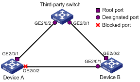
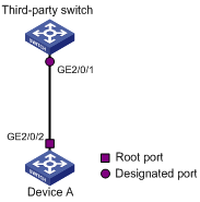
Network requirements
l Device A and Device B connect to a third-party’s router and all the routers are in the same region.
l Enable Digest Snooping on Device A and Device B so that the three routers can communicate with one another.
Network diagram
Figure 1-6 Digest Snooping configuration
Configuration procedure
1) Enable Digest Snooping on Device A.
# Enable Digest Snooping on GigabitEthernet 2/0/1.
<DeviceA> system-view
[DeviceA] interface GigabitEthernet 2/0/1
[DeviceA-GigabitEthernet 2/0/1] stp config-digest-snooping
# Enable global Digest Snooping.
[DeviceA-GigabitEthernet 2/0/1] quit
[DeviceA] stp config-digest-snooping
2) Enable Digest Snooping on Device B (the same as above, omitted)
Configuring No Agreement Check
Two types of messages are used for rapid state transition on designated RSTP and MSTP ports:
l Proposal: sent by designated ports to request rapid transition
l Agreement: used to acknowledge rapid transition requests
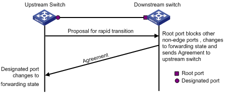
Both RSTP and MSTP switches can perform rapid transition on a designated port only when the port receives an agreement packet from the downstream switch. The differences between RSTP and MSTP switches are:
l For MSTP, the downstream device’s root port sends an agreement packet only after it receives an agreement packet from the upstream device.
l For RSTP, the down stream device sends an agreement packet regardless of whether an agreement packet from the upstream device is received.
Figure 1-7 and Figure 1-8 show the rapid state transition mechanism on MSTP and RSTP designated ports.
Figure 1-7 Rapid state transition of an MSTP designated port
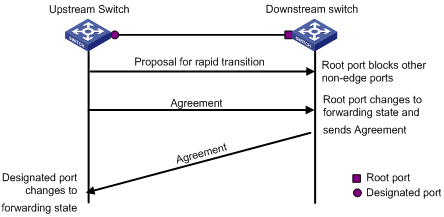
Figure 1-8 Rapid state transition of an RSTP designated port
If the upstream device comes from another vendor, the rapid state transition implementation may be limited. For example, when the upstream device adopts RSTP, and the downstream device adopts MSTP and does not support RSTP mode, the root port on the downstream device receives no agreement packet from the upstream device and thus sends no agreement packets to the upstream device. As a result, the designated port of the upstream switch fails to transit rapidly and can only change to the forwarding state after a period twice the Forward Delay.
In this case, you can enable the No Agreement Check feature on the downstream device’s port to enable the designated port of the upstream device to transit its state rapidly.
Configuration Prerequisites
l A device is connected to an upstream device supporting MSTP via a point-to-point link.
l Configure the same region name, revision level and VLAN-to-MSTI mappings on the two devices, thus assigning them to the same region.
Configuration Procedure
Follow these steps to configure No Agreement Check:
|
To do... |
Use the command... |
Remarks |
|
|
Enter system view |
system-view |
— |
|
|
Enter port or port group view |
Enter Ethernet or Layer-2 aggregate port view |
interface interface-type interface-number |
Required Use either command. Configurations made in port view will take effect on the current port only; configurations made in port group view will take effect on all ports in the port group. |
|
Enter port group view |
port-group manual port-group-name |
||
|
Enable No Agreement Check |
stp no-agreement-check |
Required Not enabled by default |
|
![]()
The No Agreement Check feature can only take effect on the root port or Alternate port after enabled.
Configuration Example
Network requirements
l Device A connects to a third-party’s device that has different MSTP implementation. Both switches are in the same region.
l Another vendor’s device is the regional root bridge, and Device A is the downstream device.
Network diagram
Figure 1-9 No Agreement Check configuration
Configuration procedure
# Enable No Agreement Check on GigabitEthernet 2/0/2 of Device A.
<DeviceA> system-view
[DeviceA] interface GigabitEthernet 2/0/2
[DeviceA-GigabitEthernet 2/0/2] stp no-agreement-check
Configuring Protection Functions
An MSTP-enabled device supports the following protection functions:
l BPDU guard
l Root guard
l Loop guard
l TC-BPDU attack guard
![]()
Among loop guard, root guard and edge port settings, only one function can take effect on a port at the same time.
Configuration prerequisites
MSTP has been correctly configured on the device.
Enabling BPDU Guard
![]()
l We recommend that you enable BPDU guard on a device with edge ports configured.
l BPDU Guard does not take effect on loopback test-enabled ports. For information about loopback test, refer to Ethernet Interface Configuration in the Access Volume.
For access layer devices, the access ports generally connect directly with user terminals (such as PCs) or file servers. In this case, the access ports are configured as edge ports to allow rapid transition. When these ports receive configuration BPDUs, the system will automatically set these ports as non-edge ports and start a new spanning tree calculation process. This will cause a change of network topology. Under normal conditions, these ports should not receive configuration BPDUs. However, if someone forges configuration BPDUs maliciously to attack the devices, network instability will occur.
MSTP provides the BPDU guard function to protect the system against such attacks. With the BPDU guard function enabled on the devices, when edge ports receive configuration BPDUs, MSTP will close these ports and notify the NMS that these ports have been closed by MSTP. Those ports closed thereby can be restored only by the network administers.
Make this configuration on a device with edge ports configured.
Follow these steps to enable BPDU guard:
|
To do... |
Use the command... |
Remarks |
|
Enter system view |
system-view |
— |
|
Enable the BPDU guard function for the device |
stp bpdu-protection |
Required Disabled by default |
Enabling Root Guard
![]()
We recommend that you enable root guard on a designated port.
The root bridge and secondary root bridge of a panning tree should be located in the same MST region. Especially for the CIST, the root bridge and secondary root bridge are generally put in a high-bandwidth core region during network design. However, due to possible configuration errors or malicious attacks in the network, the legal root bridge may receive a configuration BPDU with a higher priority. In this case, the current legal root bridge will be superseded by another device, causing an undesired change of the network topology. As a result, the traffic that should go over high-speed links is switched to low-speed links, resulting in network congestion.
To prevent this situation from happening, MSTP provides the root guard function to protect the root bridge. If the root guard function is enabled on a designated port on a root bridge, this port will keep playing the role of designated port on all MSTIs. Once this port receives a configuration BPDU with a higher priority from an MSTI, it immediately sets that port to the listening state in the MSTI, without forwarding the packet (this is equivalent to disconnecting the link connected with this port in the MSTI). If the port receives no BPDUs with a higher priority within twice the forwarding delay, the port will revert to its original state.
Make this configuration on a designated port.
Follow these steps to enable root guard:
|
To do... |
Use the command... |
Remarks |
|
|
Enter system view |
system-view |
— |
|
|
Enter port view or port group view |
Enter Ethernet or Layer-2 aggregate port view |
interface interface-type interface-number |
Required Use either command. Configurations made in port view will take effect on the current port only; configurations made in port group view will take effect on all ports in the port group. |
|
Enter port group view |
port-group manual port-group-name |
||
|
Enable the root guard function for the port(s) |
stp root-protection |
Required Disabled by default |
|
Enabling Loop Guard
![]()
We recommend that you enable loop guard on the root port or an alternate port of a device.
By keeping receiving BPDUs from the upstream device, a device can maintain the state of the root port and blocked ports. However, due to link congestion or unidirectional link failures, these ports may fail to receive BPDUs from the upstream devices. In this case, the downstream device will reselect the port roles: those ports in forwarding state that failed to receive upstream BPDUs will become designated ports, and the blocked ports will transition to the forwarding state, resulting in loops in the switched network. The loop guard function can suppress the occurrence of such loops.
If a loop guard–enabled port fails to receive BPDUs from the upstream device, and if the port took part in STP calculation, all the instances on the port, no matter what roles the port plays, will be set to, and stay in, the Discarding state.
Make this configuration on the root port or an alternate port of a device.
Follow these steps to enable loop guard:
|
To do... |
Use the command... |
Remarks |
|
|
Enter system view |
system-view |
— |
|
|
Enter port view or port group view |
Enter Ethernet or Layer-2 aggregate port view |
interface interface-type interface-number |
Required Use either command. Configurations made in port view will take effect on the current port only; configurations made in port group view will take effect on all ports in the port group. |
|
Enter port group view |
port-group manual port-group-name |
||
|
Enable the loop guard function for the port(s) |
stp loop-protection |
Required Disabled by default |
|
Enabling TC-BPDU Attack Guard
When receiving a TC-BPDU (a BPDU used as notification of a topology change), the device will delete the corresponding forwarding address entry. If someone forges TC-BPDUs to attack the device, the device will receive a larger number of TC-BPDUs within a short time, and frequent deletion operations bring a big burden to the device and hazard network stability.
With the TC-BPDU guard function enabled, the device limits the maximum number of times of immediately deleting forwarding address entries within 10 seconds after it receives the first TC-BPDUs to the value set with the stp tc-protection threshold command (assume the value is X). At the same time, the system monitors whether the number of TC-BPDUs received within that period of time is larger than X. If so, the device will perform another deletion operation after that period of time elapses. This prevents frequent deletion of forwarding address entries.
Follow these steps to enable TC-BPDU attack guard:
|
To do... |
Use the command... |
Remarks |
|
Enter system view |
system-view |
— |
|
Enable the TC-BPDU attack guard function |
stp tc-protection enable |
Optional Enabled by default |
|
Configure the maximum number of times the device deletes forwarding address entries within a certain period of time immediately after it receives the first TC-BPDU |
stp tc-protection threshold number |
Optional 6 by default |
![]()
We recommend that you keep this feature enabled.
Remotely Configuring MSTP for an ONU
An S7500E switch installed with an OLT card can work as an EPON OLT. In this case, you can remotely configure MSTP for an ONU attached to the OLT in ONU port view, as shown in the table below.
Note that:
l An ONU port supports STP/RSTP/MSTP. However, an ONU port supports only MSTI 0 among all MSTIs.
l The STP priority of an ONU port is fixed to 0. To ensure the network operates normally, do not configure the ONU as the STP root bridge.
![]()
l When STP is enabled globally on an OLT switch, you must enable STP on all ONUs.
l STP runs normally only when all attached ONUs are H3C ONUs.
l STP configurations in the system view of the OLT switch take effect on all attached ONUs.
l An ONU port supports only MSTI 0 among all MSTIs. Therefore, the MST region configuration on the OLT switch does not take effect on the attached ONUs.
Follow these steps to configure MSTP for an ONU port:
|
To do… |
Use the command… |
Remarks |
|
Enter system view |
system-view |
— |
|
Enter ONU port view |
interface interface-type interface-number |
Required In Ethernet port view, the configuration mentioned below takes effect on the current port only. |
|
Configure the maximum transmission rate of the port |
stp transmit-limit packet-number |
Optional 10 by default |
|
Configure the port as an edge port |
stp edged-port enable |
Required By default, no port is an edge port. |
|
Configure the path cost of the port |
stp cost cost |
Optional By default, MSTP automatically calculates the path cost of each port. |
|
Configure the link type of the port |
stp point-to-point { auto | force-false | force-true } |
Optional The default setting is auto; namely the device automatically detects whether an Ethernet port connects to a point-to-point link. |
|
Enable the MSTP feature for the port |
stp enable |
Optional Enabled by default. |
|
Perform mCheck |
stp mcheck |
Required |
|
Enable digest snooping on the port |
stp config-digest-snooping |
Required Disabled by default |
|
Enable No Agreement Check on the port |
stp no-agreement-check |
Required Disabled by default |
|
Enable root guard on the port |
stp root-protection |
Required Disabled by default |
|
Enable loop guard on the port |
stp loop-protection |
Required Disabled by default |
![]()
MSTP configuration commands in ONU port view are the same as those in Ethernet port view, and thus are not otherwise described.
Displaying and Maintaining MSTP
|
To do... |
Use the command... |
Remarks |
|
View information about abnormally blocked ports |
display stp abnormal-port |
Available in any view |
|
View information about ports blocked by STP protection actions |
display stp down-port |
Available in any view |
|
View the information of port role calculation history for the specified MSTI or all MSTIs |
display stp [ instance instance-id ] history [ slot slot-number ] |
Available in any view |
|
View the statistics of TC/TCN BPDUs sent and received by all ports in the specified MSTI or all MSTIs |
display stp [ instance instance-id ] tc [ slot slot-number ] |
Available in any view |
|
View the status information and statistics information of MSTP |
display stp [ instance instance-id ] [ interface interface-list | slot slot-number ] [ brief ] |
Available in any view |
|
View the MST region configuration information that has taken effect |
display stp region-configuration |
Available in any view |
|
View the root bridge information of all MSTIs |
display stp root |
Available in any view |
|
Clear the statistics information of MSTP |
reset stp [ interface interface-list ] |
Available in user view |
MSTP Configuration Example
Network requirements
Configure MSTP so that packets of different VLANs are forwarded along different spanning trees. The specific configuration requirements are as follows:
l All devices on the network are in the same MST region.
l Packets of VLAN 10 are forwarded along MSTI 1, those of VLAN 30 are forwarded along MSTI 3, those of VLAN 40 are forwarded along MSTI 4, and those of VLAN 20 are forwarded along MSTI 0.
l Device A and Device B are distribution layer devices, while Device C and Device D are access layer devices. VLAN 10 and VLAN 30 are terminated on the distribution layer devices, and VLAN 40 is terminated on the access layer devices, so the root bridges of MSTI 1 and MSTI 3 are Device A and Device B respectively, while the root bridge of MSTI 4 is Device C.
Network diagram
Figure 1-10 Network diagram for MSTP configuration
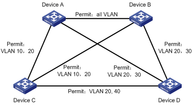
![]()
“Permit:“ beside each link in the figure is followed by the VLANs the packets of which are permitted to pass this link.
Configuration procedure
1) Configuration on Device A
# Enter MST region view.
<DeviceA> system-view
[DeviceA] stp region-configuration
# Configure the region name, VLAN-to-MSTI mappings and revision level of the MST region.
[DeviceA-mst-region] region-name example
[DeviceA-mst-region] instance 1 vlan 10
[DeviceA-mst-region] instance 3 vlan 30
[DeviceA-mst-region] instance 4 vlan 40
[DeviceA-mst-region] revision-level 0
# Activate MST region configuration manually.
[DeviceA-mst-region] active region-configuration
[DeviceA-mst-region] quit
# Define Device A as the root bridge of MSTI 1.
[DeviceA] stp instance 1 root primary
# Enable MSTP for the device.
[DeviceA] stp enable
# View the MST region configuration information that has taken effect.
[DeviceA] display stp region-configuration
Oper configuration
Format selector :0
Region name :example
Revision level :0
Instance Vlans Mapped
0 1 to 9, 11 to 29, 31 to 39, 41 to 4094
1 10
3 30
4 40
2) Configuration on Device B
# Enter MST region view.
<DeviceB> system-view
[DeviceB] stp region-configuration
# Configure the region name, VLAN-to-MSTI mappings and revision level of the MST region.
[DeviceB-mst-region] region-name example
[DeviceB-mst-region] instance 1 vlan 10
[DeviceB-mst-region] instance 3 vlan 30
[DeviceB-mst-region] instance 4 vlan 40
[DeviceB-mst-region] revision-level 0
# Activate MST region configuration manually.
[DeviceB-mst-region] active region-configuration
[DeviceB-mst-region] quit
# Define Device B as the root bridge of MSTI 3.
[DeviceB] stp instance 3 root primary
# Enable MSTP for the device.
[DeviceB] stp enable
# View the MST region configuration information that has taken effect.
[DeviceB] display stp region-configuration
Oper configuration
Format selector :0
Region name :example
Revision level :0
Instance Vlans Mapped
0 1 to 9, 11 to 29, 31 to 39, 41 to 4094
1 10
3 30
4 40
3) Configuration on Device C.
# Enter MST region view.
<DeviceC> system-view
[DeviceC] stp region-configuration
[DeviceC-mst-region] region-name example
# Configure the region name, VLAN-to-MSTI mappings and revision level of the MST region.
[DeviceC-mst-region] instance 1 vlan 10
[DeviceC-mst-region] instance 3 vlan 30
[DeviceC-mst-region] instance 4 vlan 40
[DeviceC-mst-region] revision-level 0
# Activate MST region configuration manually.
[DeviceC-mst-region] active region-configuration
[DeviceC-mst-region] quit
# Define Device C as the root bridge of MSTI 4.
[DeviceC] stp instance 4 root primary
# Enable MSTP for the device.
[DeviceC] stp enable
# View the MST region configuration information that has taken effect.
[DeviceC] display stp region-configuration
Oper configuration
Format selector :0
Region name :example
Revision level :0
Instance Vlans Mapped
0 1 to 9, 11 to 29, 31 to 39, 41 to 4094
1 10
3 30
4 40
4) Configuration on Device D.
# Enter MST region view.
<DeviceD> system-view
[DeviceD] stp region-configuration
[DeviceD-mst-region] region-name example
# Configure the region name, VLAN-to-MSTI mappings and revision level of the MST region.
[DeviceD-mst-region] instance 1 vlan 10
[DeviceD-mst-region] instance 3 vlan 30
[DeviceD-mst-region] instance 4 vlan 40
[DeviceD-mst-region] revision-level 0
# Activate MST region configuration manually.
[DeviceD-mst-region] active region-configuration
[DeviceD-mst-region] quit
# Enable MSTP for the device.
[DeviceD] stp enable
# View the MST region configuration information that has taken effect.
[DeviceD] display stp region-configuration
Oper configuration
Format selector :0
Region name :example
Revision level :0
Instance Vlans Mapped
0 1 to 9, 11 to 29, 31 to 39, 41 to 4094
1 10
3 30
4 40
