- Table of Contents
-
- 01-Access Volume
- 00-Access Volume Organization
- 01-Ethernet Interface Configuration
- 02-Link Aggregation Configuration
- 03-Port Isolation Configuration
- 04-Service Loopback Group Configuration
- 05-DLDP Configuration
- 06-Smart Link Configuration
- 07-LLDP Configuration
- 08-VLAN Configuration
- 09-GVRP Configuration
- 10-QinQ Configuration
- 11-BPDU Tunneling Configuration
- 12-VLAN Mapping Configuration
- 13-Ethernet OAM Configuration
- 14-Connectivity Fault Detection Configuration
- 15-EPON-OLT Configuration
- 16-MSTP Configuration
- 17-RRPP Configuration
- 18-Mirroring Configuration
- Related Documents
-
| Title | Size | Download |
|---|---|---|
| 02-Link Aggregation Configuration | 130.72 KB |
Table of Contents
1 Link Aggregation Configuration
Understanding Link Aggregation
Basic Concepts of Link Aggregation
Load Sharing Mode of an Aggregation Group
Link Aggregation Configuration Task List
Configuring an Aggregation Group
Configuring a Static Aggregation Group
Configuring a Dynamic Aggregation Group
Configuring an Aggregate Interface
Configuring the Description of an Aggregate Interface
Enabling LinkUp/LinkDown Trap Generation for an Aggregate Interface
Shutting Down an Aggregate Interface
Displaying and Maintaining Link Aggregation
Link Aggregation Configuration Examples
When configuring link aggregation, go to these sections for information you are interested in:
l Overview
l Link Aggregation Configuration Task List
l Configuring a Static Aggregation Group
l Configuring a Dynamic Aggregation Group
l Configuring an Aggregate Interface
l Displaying and Maintaining Link Aggregation
l Link Aggregation Configuration Examples
Overview
Understanding Link Aggregation
Link aggregation aggregates multiple physical Ethernet ports into one logical link, also called an aggregation group.
It allows you to increase bandwidth by distributing traffic across the member ports in the aggregation group. In addition, it provides reliable connectivity because these member ports can dynamically back up each other.
Basic Concepts of Link Aggregation
Aggregate interface
An aggregate interface is a logical Layer-2 or Layer-3 aggregate interface.
Aggregation group
An aggregation group is a collection of Ethernet interfaces. When you create an aggregate interface, an aggregation group numbered the same is created automatically depending on the type of the aggregate interface:
l If the aggregate interface is a Layer 2 interface, a Layer-2 aggregation group is created. You can assign only Layer-2 Ethernet interfaces to the group.
l If the aggregate interface is a Layer-3 interface, a Layer-3 aggregation group is created. You can assign only Layer-3 Ethernet interfaces to the group.
![]()
The curreent device only supports Layer-2 aggregation groups.
States of the member ports in an aggregation group
A member port in an aggregation group can be in one of the following two states:
l Selected: a selected port can forward user traffic.
l Unselected: an unselected port cannot forward user traffic.
The rate of an aggregate interface is the sum of the selected member ports’ rates. The duplex mode of an aggregate interface is consistent with that of the selected member ports. Note that all selected member ports use the same duplex mode.
For how the state of a member port is determined, refer to Static aggregation mode and Dynamic aggregation mode.
LACP protocol
The Link Aggregation Control Protocol (LACP) is defined in IEEE 802.3ad. It uses link aggregation control protocol data units (LACPDUs) for information exchange between LACP-enabled devices.
LACP is automatically enabled on interfaces in a dynamic aggregation group. For information about dynamic aggregation groups, refer to Dynamic aggregation mode. An LACP-enabled interface sends LACPDUs to notify the remote system (the partner) of its system LACP priority, system MAC address, LACP port priority, port number, and operational key. Upon receiving an LACPDU, the partner compares the received information with the information received on other interfaces to determine the interfaces that can operate as selected interfaces. This allows the two systems to reach an agreement on which link aggregation member ports should be placed in selected state.
Operational key
When aggregating ports, link aggregation control automatically assigns each port an operational key based on port attributes, including the port rate, duplex mode and link state configuration.
In an aggregation group, all selected ports are assigned the same operational key..
Class-two configurations
The contents of class-two configurations are listed in Table 1-1. In an aggregation group, a member port different from the aggregate interface in the class-two configurations cannot be a selected port.
Table 1-1 Class-two configurations
|
Type |
Considerations |
|
Port isolation |
Whether a port has joined an isolation group |
|
QinQ |
QinQ enable state (enable/disable), outer VLAN tags to be added, inner-to-outer VLAN priority mappings, inner-to-outer VLAN tag mappings, inner VLAN ID substitution mappings |
|
VLAN |
Permitted VLAN IDs, default VLAN, link type (trunk, hybrid, or access), IP subnet-based VLAN configuration, protocol-based VLAN configuration, tag mode |
|
Port attributes |
Rate, duplex mode, and state (up/down) |
|
MAC address learning |
MAC address learning capability, MAC address learning limit, forwarding of frames with unknown destination MAC addresses after the upper limit of the MAC address table is reached |
![]()
l Some configurations are called class-one configurations. Such configurations, for example, GVRP and MSTP, can be configured on aggregate interfaces and member ports but will not affect the select state of link aggregation member ports.
l The change of a class-two configuration setting may affect the select state of link aggregation member ports and thus the ongoing service. To prevent unconsidered change, a message warning of the hazard will be displayed when you attempt to change a class-two setting, upon which you can decide whether to continue your change operation.
Link Aggregation Modes
Depending on the link aggregation procedure, link aggregation operates in one of the following two modes:
Static aggregation mode
LACP is disabled on the member ports in a static aggregation group. In a static aggregation group, the system sets a port to selected or unselected state by the following rules:
l Select a port as the reference port from the ports that are in up state and with the same class-two configurations as the corresponding aggregate interface. These ports are selected in the order of full duplex/high speed, full duplex/low speed, half duplex/high speed, and half duplex/low speed, with full duplex/high speed being the most preferred. If two ports with the same duplex mode/speed pair are present, the one with the lower port number wins out.
l Consider the ports in up state with the same port attributes and class-two configurations as the reference port as candidate selected ports, and set all others in the unselected state.
l Static aggregation limits the number of selected ports in an aggregation group. When the number of the candidate selected ports is under the limit, all the candidate selected ports become selected ports. When the limit is exceeded, set the candidate selected ports with smaller port numbers in the selected state and those with greater port numbers in the unselected state.
l If all the member ports are down, set their states to unselected.
In addition, a port that joins the aggregation group after the limit on the number of selected ports has been reached will not be placed in the selected state even if it should be in normal cases. This can prevent the ongoing traffic on the current selected ports from being interrupted. You should avoid the situation however, as this may cause the selected/unselected state of a port to change after a reboot.
![]()
A port that joins the aggregation group after the limit on the number of selected ports has been reached will not be placed in the selected state even if it should be in normal cases. This can prevent the ongoing traffic on the current selected ports from being interrupted. You should avoid the situation however, as this may cause the selected/unselected state of a port to change after a reboot.
Dynamic aggregation mode
LACP is enabled on member ports in a dynamic aggregation group.
In a dynamic aggregation group,
l A selected port can receive and transmit LACPDUs.
l An unselected port can receive and send LACPDUs only if it is up and with the same configurations as those on the aggregate interface.
In a dynamic aggregation group, the system sets the ports to selected or unselected state in the following steps.
The local system (the actor) negotiates with the remote system (the partner) to determine port state based on the port IDs on the end with the preferred system ID. The following is the detailed negotiation procedure:
l Compare the system ID (comprising the system LACP priority and the system MAC address) of the actor with that of the partner. The system with the lower LACP priority wins out. If they are the same, compare the system MAC addresses. The system with the smaller MAC address wins out.
l Compare the port IDs of the ports on the system with the smaller system ID. A port ID comprises a port LACP priority and a port number. First compare the port LACP priorities. The port with the lower LACP priority wins out. If two ports are with the same LACP priority, compare their port numbers. The port with the smaller port ID, that is, the port with smaller port number, is selected as the reference port.
l If a port (in up state) is with the same port attributes and class-two configuration as the reference port, and the peer port of the port is with the same port attributes and class-two configurations as the peer port of the reference port, consider the port as a candidate selected port; otherwise set the port to the unselected state.
l The number of selected ports that an aggregation group can contain is limited. When the number of candidate selected ports is under the limit, all the candidate selected ports are set to selected state. When the limit is exceeded, the system selects the candidate selected ports with smaller port IDs as the selected ports, and set other candidate selected ports to unselected state. At the same time, the peer device, being aware of the changes, changes the state of its ports accordingly.
![]()
For static and dynamic aggregation modes:
l In an aggregation group, the port to be a selected port must be the same as the reference port in port attributes, and class-two configurations. To keep these configurations consistent, you should configure the port manually.
l Because changing a port attribute or class-two configuration setting of a port may cause the select state of the port and other member ports to change and thus affects services, you are recommended to do that with caution.
Load Sharing Mode of an Aggregation Group
A link aggregation groups operates in load sharing aggregation mode or non-load sharing mode.
The system sets the load sharing mode of an aggregation group as follows:
l When hardware resources are available, a link aggregation group with at least two selected ports operates in load sharing mode. The load sharing mode of a link aggregation group with only one selected port is non-load sharing mode.
l When hardware resources become depleted (the number of created link aggregation groups reaches the maximum), all new link aggregation groups operate in non-load sharing mode.
![]()
l After you remove all ports but one selected port from a load-sharing aggregation group, the aggregation group remains to be a load sharing group.
l A load-sharing aggregation group contains at least one selected port while a non-load-sharing aggregation group can only have one selected port at most.
l After hardware resources become depleted, all new link aggregation groups operate in non-load sharing mode. They will not perform load sharing even after resources become available again for example after some aggregation groups are removed. To have them perform load sharing, you can re-enable their corresponding aggregation interfaces by shutting down and then bringing up the interfaces.
Link Aggregation Configuration Task List
Complete the following tasks to configure link aggregation:
|
Task |
Remarks |
|
|
Select either task |
||
|
Optional |
||
|
Enabling LinkUp/LinkDown Trap Generation for an Aggregate Interface |
Optional |
|
|
Optional |
||
Configuring an Aggregation Group
![]()
l The following ports cannot be assigned to an aggregation group: RRPP-enabled ports, MAC address authentication-enabled ports, port security-enabled ports, portal-enabled, IP source guard-enabled ports, and 802.1x-enabled ports.
l You are discouraged to assign the reflector ports for port mirroring to an aggregation group. For more information about reflector ports, refer to Port Mirroring Configuration in the Access Volume.
Configuring a Static Aggregation Group
Follow these steps to configure a Layer-2 static aggregation group:
|
To do... |
Use the command... |
Remarks |
|
Enter system view |
system-view |
— |
|
Create a Layer-2 aggregate interface and enter the Layer-2 aggregate interface view |
interface bridge-aggregation interface-number |
Required When you create a Layer-2 aggregate interface, a Layer-2 static aggregation group numbered the same is created automatically. |
|
Exit to system view |
quit |
— |
|
Enter Layer-2 Ethernet interface view |
interface interface-type interface-number |
Required Repeat the two steps to assign multiple Ethernet interfaces to the aggregation group. |
|
Assign the Ethernet interface to the aggregation group |
port link-aggregation group number |
![]()
l Removing a Layer-2 aggregate interface also removes the corresponding aggregation group. At the same time, the member ports of the aggregation group, if any, leave the aggregation group.
l To guarantee a successful static aggregation, ensure that the ports at the two ends of each link to be aggregated are consistent in the selected/unselected state.
l On an S7500E switch, for an aggregation group with more than eight member ports, the system always places the lowest-numbered eight ports in selected state, and places the other ports in unselected state. If a port whose port number is smaller than that of the highest-numbered selected port joins the aggregation group, the port will become a selected port, and the former highest numbered selected port will become an unselected port. Therefore, when connecting your S7500E switch to a device using a different link aggregation implementation, you should try to avoid configuring an aggregation group with more than eight ports, thus avoiding data loss.
Configuring a Dynamic Aggregation Group
Follow these steps to configure a Layer-2 dynamic aggregation group:
|
To do... |
Use the command... |
Remarks |
|
Enter system view |
system-view |
— |
|
Set the system LACP priority |
lacp system-priority system-priority |
Optional By default, the system LACP priority is 32768. Changing the system LACP priority may affect the selected/unselected state of the ports in the dynamic aggregation group. |
|
Create a Layer-2 aggregate interface and enter the Layer-2 aggregate interface view |
interface bridge-aggregation interface-number |
Required When you create a Layer-2 aggregate interface, a Layer-2 static aggregation group numbered the same is created automatically. |
|
Configure the aggregation group to work in dynamic aggregation mode |
link-aggregation mode dynamic |
Required By default, an aggregation group works in static aggregation mode. |
|
Exit to system view |
quit |
— |
|
Enter Layer-2 Ethernet interface view |
interface interface-type interface-number |
Required Repeat the two steps to assign multiple Ethernet interfaces to the aggregation group. |
|
Assign the Ethernet interface to the aggregation group |
port link-aggregation group number |
|
|
Assign the port a LACP priority |
lacp port-priority port-priority |
Optional By default, the LACP priority of a port is 32768. Changing the LACP priority of a port may affect the selected/unselected state of the ports in the dynamic aggregation group. |
![]()
l Removing a dynamic aggregate interface also removes the corresponding aggregation group. At the same time, the member ports of the aggregation group, if any, leave the aggregation group.
l To guarantee a successful dynamic aggregation, ensure that the peer ports of the ports aggregated at one end are also aggregated. The two ends can automatically negotiate the selected state of the ports.
l When a load-sharing aggregation group becomes a non-load-sharing aggregation group because of insufficient load sharing resources, one of the following problems may occur: the number of selected ports of the actor is inconsistent with that of the partner, which may result in incorrect traffic forwarding; the peer port of a selected port is an unselected one, which may result in upper-layer protocol and traffic forwarding anomalies. You should fully consider the situation when making configuration.
Configuring an Aggregate Interface
You can perform the following configurations for an aggregate interface:
l Configuring the Description of an Aggregate Interface
l Enabling LinkUp/LinkDown Trap Generation for an Aggregate Interface
l Shutting Down an Aggregate Interface
Configuring the Description of an Aggregate Interface
Follow these steps to configure the description of an aggregate interface:
|
To do... |
Use the command... |
Remarks |
|
Enter system view |
system-view |
— |
|
Enter Layer-2 aggregate interface view |
interface bridge-aggregation interface-number |
— |
|
Configure the description of the aggregate interface |
description text |
Optional By default, the description of an interface is interface-name Interface, such as Bridge-Aggregation1 Interface. |
Enabling LinkUp/LinkDown Trap Generation for an Aggregate Interface
To enable an aggregate interface to generate linkUp/linkDown trap messages when the state of the interface changes, you should enable linkUp/linkDown trap generation on the aggregate interface.
Follow these steps to enable linkUp/linkDown trap generation for an aggregate interface:
|
To do... |
Use the command... |
Remarks |
|
Enter system view |
system-view |
— |
|
Enable the trap function globally |
snmp-agent trap enable [ standard [ linkdown | linkup ] * ] |
Optional By default, linkUp/linkDown trap generation is enabled globally and on all interfaces. |
|
Enter Layer-2 aggregate interface view |
interface bridge-aggregation interface-number |
— |
|
Enable linkUp/linkDown trap generation for the aggregate interface |
enable snmp trap updown |
Optional Enabled by default |
Shutting Down an Aggregate Interface
Shutting down or bringing up an aggregate interface affects the selected state of the ports in the corresponding aggregation group. When an aggregate interface is shut down, all selected ports in its aggregation group become unselected; when the aggregate interface is brought up, the selected state of the ports in the corresponding aggregation group is re-calculated.
Follow these steps to shut down an aggregate interface:
|
To do... |
Use the command... |
Remarks |
|
Enter system view |
system-view |
— |
|
Enter Layer-2 aggregate interface view |
interface bridge-aggregation interface-number |
— |
|
Shut down the aggregate interface |
shutdown |
Required By default, aggregate interfaces are up. |
Displaying and Maintaining Link Aggregation
|
To do... |
Use the command... |
Remarks |
|
Display the local system ID |
display lacp system-id |
Available in any view |
|
Display link aggregation details of ports |
display link-aggregation member-port [ interface-type interface-number [ to interface-type interface-number ] ] |
Available in any view |
|
Display the summary information of all aggregation groups |
display link-aggregation summary |
Available in any view |
|
Display detailed information of aggregation groups |
display link-aggregation verbose [ bridge-aggregation [ interface-number ] ] |
Available in any view |
|
Clear the LACP statistics of ports |
reset lacp statistics [ interface interface-type interface-number [ to interface-type interface-number ] ] |
Available in user view |
Link Aggregation Configuration Examples
![]()
In an aggregation group, the port to be a selected port must be the same as the reference port in port attributes, and class-two configurations. To keep these configurations consistent, you should configure the port manually.
l Because changing a port attribute or class-two configuration setting of a port may cause the select state of the port and other member ports to change and thus affects services, you are recommended to do that with caution.
l Reference port: Select a port as the reference port from the ports that are in up state and with the same class-two configurations as the corresponding aggregate interface. These ports are selected in the order of full duplex/high speed, full duplex/low speed, half duplex/high speed, and half duplex/low speed, with full duplex/high speed being the most preferred. If two ports with the same duplex mode/speed pair are present, the one with the lower port number wins out.
l Port attribute configurations include the rate, duplex mode, and link state (up/down) configurations of a port.
l Class-two configurations: refer to Class-two configurations.
Network Requirements
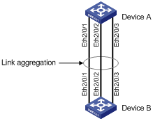
As shown in Figure 1-1, aggregate ports Ethernet 2/0/1 through 2/0/3 of Device A into an aggregate interface to connect to Device B, thus balancing outgoing traffic across the member ports. In addition, configure an appropriate load sharing mode for load-sharing link aggregation groups.
Network Diagram
Figure 1-1 Network diagram for link aggregation
Configuration Procedure
![]()
This configuration example only provides the configuration procedure on Device A. You must perform the same configuration on Device B for link aggregation to work.
Configuring a Layer-2 aggregation group if the interfaces in the diagram are Layer-2 Ethernet interfaces
1) Approach 1: static aggregation mode
# Create Layer-2 aggregate interface Bridge-aggregation 1.
[DeviceA] interface bridge-aggregation 1
[DeviceA-Bridge-Aggregation1] quit
# Assign Layer-2 Ethernet interfaces Ethernet 2/0/1 through Ethernet 2/0/3 to aggregation group 1.
[DeviceA] interface ethernet 2/0/1
[DeviceA-Ethernet2/0/1] port link-aggregation group 1
[DeviceA-Ethernet2/0/1] interface ethernet 2/0/2
[DeviceA-Ethernet2/0/2] port link-aggregation group 1
[DeviceA-Ethernet2/0/2] interface ethernet 2/0/3
[DeviceA-Ethernet2/0/3] port link-aggregation group 1
2) Approach 2: dynamic aggregation mode
# Create a Layer-2 aggregate interface Bridge-Aggregation 1 and configure the interface to work in dynamic aggregation mode.
<DeviceA> system-view
[DeviceA] interface bridge-aggregation 1
[DeviceA-Bridge-Aggregation1] link-aggregation mode dynamic
[DeviceA-Bridge-Aggregation1] quit
# Assign Layer-2 Ethernet interfaces Ethernet 2/0/1 through Ethernet 2/0/3 to aggregation group 1.
[DeviceA] interface ethernet 2/0/1
[DeviceA-Ethernet2/0/1] port link-aggregation group 1
[DeviceA-Ethernet2/0/1] interface ethernet 2/0/2
[DeviceA-Ethernet2/0/2] port link-aggregation group 1
[DeviceA-Ethernet2/0/2] interface ethernet 2/0/3
[DeviceA-Ethernet2/0/3] port link-aggregation group 1
