- Table of Contents
-
- 01-Access Volume
- 00-Access Volume Organization
- 01-Ethernet Interface Configuration
- 02-Link Aggregation Configuration
- 03-Port Isolation Configuration
- 04-Service Loopback Group Configuration
- 05-DLDP Configuration
- 06-Smart Link Configuration
- 07-LLDP Configuration
- 08-VLAN Configuration
- 09-GVRP Configuration
- 10-QinQ Configuration
- 11-BPDU Tunneling Configuration
- 12-VLAN Mapping Configuration
- 13-Ethernet OAM Configuration
- 14-Connectivity Fault Detection Configuration
- 15-EPON-OLT Configuration
- 16-MSTP Configuration
- 17-RRPP Configuration
- 18-Mirroring Configuration
- Related Documents
-
| Title | Size | Download |
|---|---|---|
| 17-RRPP Configuration | 1.05 MB |
Table of Contents
Configuring Assistant Edge Node
Displaying and Maintaining RRPP
RRPP Typical Configuration Examples
Configuring Single Ring Topology
Configuring Single-Domain Intersecting Ring Topology
Configuring Intersecting-Ring Load Balancing
When configuring RRPP, go to these sections for information you are interested in:
l RRPP Configuration Task List
l Configuring Assistant Edge Node
l Displaying and Maintaining RRPP
l RRPP Typical Configuration Examples
RRPP Overview
The Rapid Ring Protection Protocol (RRPP) is a link layer protocol designed for Ethernet rings. RRPP can prevent broadcast storms caused by data loops when an Ethernet ring is healthy, and rapidly restore the communication paths between the nodes after a link is disconnected on the ring.
Compared with the IEEE spanning tree protocols, RRPP features:
l Fast topology convergence
l Convergence time independent of Ethernet ring size
Background
Currently, either STP or RRPP can be used to eliminate Layer-2 loops. STP is mature; however, its convergence time is several seconds. Rapid Ring Protection Protocol (RRPP) is an Ethernet ring-specific data link layer protocol, and is faster than STP in convergence. Additionally, the convergence time of RRPP is independent of the number of nodes in the Ethernet ring, and therefore, RRPP can be applied to large-diameter networks.
Basic Concepts in RRPP
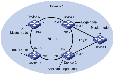
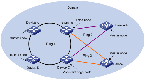
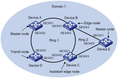
Figure 1-1 RRPP networking diagram
RRPP domain
The interconnected devices with the same domain ID and control VLANs constitute an RRPP domain. An RRPP contains the following elements: primary ring, subring, master node, transit node, primary port, secondary port, common port, and edge port.
As shown in Figure 1-1, Domain 1 is an RRPP domain, including two RRPP rings: Ring 1 and Ring 2. All the nodes on the two RRPP rings belong to the RRPP domain.
RRPP ring
A ring-shaped Ethernet topology is called an RRPP ring. An RRPP ring falls into primary ring and subring. You can set a ring as either the primary ring or a subring by specifying its ring level. The primary ring is configured to be of level 0; the subring is configured to be of level 1. An RRPP domain contains multiple RRPP rings, in which one ring serves as the primary ring and the other rings serve as subrings.
As shown in Figure 1-1, Domain 1 contains two RRPP rings: Ring 1 and Ring 2. Ring 1 level is set to 0, meaning the primary ring; Ring 2 level is set to 1, meaning the subring.
For a ring, there are two cases:
l Health state: All the physical links on the Ethernet ring are connected.
l Disconnect state: Some physical link on the Ethernet ring fails.
Control VLAN and data VLAN
In an RRPP domain, control VLAN is a VLAN specially designed to transfer RRPP packets.
The ports accessing an RRPP ring on each device belong to the control VLANs of the ring and only these ports can join the control VLANs.
An RRPP domain is configured with two control VLANs: one primary control VLAN, which is the control VLAN for the primary ring; one secondary control VLAN, which is the control VLAN for the subrings. All subrings in the same RRPP domain share the same secondary control VLAN. After you specify a VLAN as the primary control VLAN, the VLAN whose ID is one plus the primary control VLAN ID is configured as the secondary control VLAN automatically.
IP address configuration is prohibited on the control VLAN interfaces.
Data VLAN is a VLAN designed to transfer data packets. Both RRPP ports and non-RRPP ports can be assigned to a data VLAN.
Node
Every device on an RRPP ring is referred to as a node. Node mode includes:
l Master node: Each ring has one and only one master node. The master node initiates the polling mechanism and determines the operations to perform after topology changes.
l Transit node: All the nodes excluding the master node on the primary ring; and all the nodes on a subring except for the master node and the nodes where the primary ring intersects with the subring. A transit node monitors the state of its directly connected RRPP links and notifies the master node of the link state changes, if any. The master node decides the operations to perform based on the link state changes.
l Edge node: A node residing on the primary ring and a subring at the same time. The node is a special transit node that serves as a transit node on the primary ring and an edge node on the subring.
l Assistant-edge node: A node residing on the primary ring and a subring at the same time. The node is a special transit node that serves as a transit node on the primary ring and an assistant-edge node on the subring. This node is used in conjunction with the edge node to detect the integrity of the primary ring and perform loop guard.
As shown in Figure 1-1, Ring 1 is the primary ring and Ring 2 is a subring. Device A is the master node of Ring 1, Device B, Device C and Device D are the transit nodes of Ring 1. Device E is the master node of Ring 2, Device B is the edge node of Ring 2, Device C is the assistant edge node of Ring 2.
Primary port and secondary port
Each master node or transit node has two ports accessing an RRPP ring, in which one serves as the primary port and the other serves as the secondary port. You can determine the role of a port.
1) In terms of functionality, the difference between the primary port and the secondary port of a master node is:
l The primary port and the secondary port are designed to play the role of sending and receiving loop-detect packets respectively.
l When an RRPP ring is in Health state, the secondary port of the master node will logically deny data VLANs and permit only the packets of the control VLANs.
l When an RRPP ring is in disconnect state, the secondary port of the master node will permit data VLANs, that is, forward packets of data VLANs.
2) In terms of functionality, there is no difference between the primary port and the secondary port of the transit node. Both are designed for the transfer of protocol packets and data packets over an RRPP ring.
As shown in Figure 1-1, Device A is the master node of Ring 1. Port 1 and port 2 are the primary port and the secondary port of the master node on Ring 1 respectively. Device B, Device C and Device D are the transit nodes of Ring 1. Their port 1 and port 2 are the primary port and the secondary port on Ring 1 respectively.
Common port and edge port
The ports connecting the edge node and assistant-edge node to the primary ring are common ports. The ports connecting the edge node and assistant-edge node only to the subring are edge ports.
As shown in Figure 1-1, Device B and Device C lie on Ring 1 and Ring 2. Device B’s port 1 and port 2 and Device C’s port 1 and port 2 access the primary ring, so they are common ports. Device B’s port 3 and Device C’s port 3 access only the subring, so they are edge ports.
Ring group
To reduce Edge-Hello traffic, you can configure a group of subrings on the edge node or assistant-edge node. For information about Edge-Hello packets, refer to RRPP Packets. You must configure a device as the edge node of these subrings, and another device as the assistant-edge node of these subrings. Additionally, the subrings of the edge node and assistant-edge node must connect to the same link in the primary ring, so that Edge-Hello packets of the edge node of these subrings travel to the assistant-edge node of these subrings over the same link.
A ring group configured on the edge node is called an edge node ring group, and a ring group configured on an assistant-edge node is called an assistant-edge node ring group. Up to one subring in an edge node ring group is allowed to send Edge-Hello packets.
RRPP Packets
Table 1-1 shows the types of RRPP packets and their functions.
Table 1-1 RRPP packet types and their functions
|
Type |
Description |
|
Hello |
The master node initiates Hello packets to detect the integrity of a ring in a network. |
|
Link-Down |
The transit node, the edge node or the assistant edge node initiates Link-Down packets to notify the master node the disappearance of a ring in case of a link failure. |
|
Common-Flush-FDB |
The master node initiates Common-Flush-FDB packets to notify the transit nodes to update their own MAC entries and ARP/ND entries when an RRPP ring transits to disconnect state. |
|
Complete-Flush-FDB |
The master node initiates Complete-Flush-FDB packets to notify the transit nodes to update their own MAC entries and ARP/ND entries, and release blocked ports from being blocked temporarily when an RRPP ring transits into health state. |
|
Edge-Hello |
The edge node initiates Edge-Hello packets to examine the links of the primary ring between the edge node and the assistant edge node. |
|
Major-Fault |
Assistant edge node initiates Major-Fault packets to notify the edge node of a failure when a link of primary ring between edge node and assistant edge node is torn down. |
Hello and Fail Timers
When RRPP checks the link state of an Ethernet ring, the master node sends Hello packets according to the Hello timer and determines whether a secondary port receives the Hello packets based on the Fail timer.
l The Hello timer specifies the interval at which the primary port sends Hello packets.
l The Fail timer specifies the maximum delay between the primary port’s sending Hello packets and the secondary port’s receiving the Hello packets from the primary port. If the secondary port receives the Hello packets before the Fail timer expires, the overall ring is in Health state. Otherwise, the ring transits into Disconnect state.
![]()
l In an RRPP domain, a transit node learns the Hello timer value and the Fail timer value on the master node through the received Hello packets, ensuring that all nodes in the ring network are consistent in the two timer settings.
l The Fail timer value must be greater than or equal to 3 times of the Hello timer value.
l In a dual-homed-ring network, to avoid temporary loops when the primary ring fails, ensure that the difference between the Fail timer value on the master node of the subring and that on the master node of the primary ring is greater than twice the Hello timer value of the master node of the subring.
How RRPP Works
Polling mechanism
The polling mechanism is used by the master node of an RRPP ring to check the health state of the ring network.
The master node sends Hello packets out its primary port periodically, and these Hello packets travel through each transit node on the ring in turn.
l If the ring is complete, the secondary port of the master node will receive Hello packets before the Fail timer expires and the master node will keep the secondary port blocked.
l If the ring is torn down, the secondary port of the master node will not receive Hello packets before the Fail timer expires. The master node will release the secondary port from blocking data VLANs while sending Common-Flush-FDB packets to instruct all transit nodes to update their own MAC entries and ARP/ND entries.
Link down alarm mechanism
The transit node, the edge node or the assistant-edge node sends Link-Down packets to the master node immediately when they find any of its own ports belonging to an RRPP domain is down. Upon the receipt of a Link-Down packet, the master node releases the secondary port from blocking data VLANs while sending Common-Flush-FDB packet to instruct all the transit nodes, the edge nodes and the assistant-edge nodes to update their own MAC entries and ARP/ND entries. After each node updates its own entries, traffic is switched to the normal link.
Ring recovery
The master node may find the ring is restored after a period of time after the ports belonging to the RRPP domain on the transit node, the edge node or the assistant-edge node are brought up again. A temporary loop may arise in the data VLAN during this period. As a result, broadcast storm occurs.
To prevent temporary loops, non-master nodes block them immediately (and permits only the packets of the control VLAN to pass through) when they find their ports accessing the ring are brought up again. The blocked ports are activated only when the nodes ensure that no loop will be brought forth by these ports.
Broadcast storm suppression mechanism in a multi-homed subring in case of primary ring link failure
As shown in Figure 1-5, Ring 1 is the primary ring, and Ring 2 and Ring 3 are subrings. When two links of the primary ring between the edge node and the assistant edge node are down, the master nodes of Ring 2 and Ring 3 will open their respective secondary ports, and thus a loop among B, C, E and F is generated. As a result, broadcast storm occurs.
In this case, to prevent generating this loop, the edge node will block the edge port temporarily. The blocked edge port is activated only when the edge node ensures that no loop will be brought forth when the edge port is activated.
Load balancing
In a ring network, maybe traffic of multiple VLANs is transmitted at the same time. RRPP can implement load balancing for the traffic by transmitting traffic of different VLANs along different paths.
By configuring an individual RRPP domain for transmitting the traffic of the specified VLANs (refereed to as protected VLANs) in a ring network, traffic of different VLANs can be transmitted according to different topologies in the ring network. In this way, load balancing is achieved.
As shown in Figure 1-6, Ring 1 is configured as the primary ring of Domain 1 and Domain 2, which are configured with different protected VLANs. Device A is the master node of Ring 1 in Domain 1; Device B is the master node of Ring 1 in Domain 2. With such configurations, traffic of different VLANs can be transmitted on different links, and thus, load balancing is achieved in a single-ring network.
Ring group
In an edge node ring group, only an activated subring with the lowest domain ID and ring ID can send Edge-Hello packets. In an assistant-edge node ring group, any activated subring that has received Edge-Hello packets will forward these packets to the other activated subrings. With an edge node ring group and an assistant-edge node group configured, only one subring sends and receives Edge-Hello packets, thus reducing CPU workload.
As shown in Figure 1-5, Device B is the edge node of Ring 2 and Ring 3, and Device C is the assistant-edge node of Ring 2 and Ring 3. Device B and Device C need to send or receive Edge-Hello packets frequently. If more subrings are configured or load balancing is configured for more multiple domains, Device B and Device C will send or receive a mass of Edge-Hello packets.
To reduce Edge-Hello traffic, you can assign Ring 2 and Ring 3 to a ring group configured on the edge node Device B, and assign Ring 2 and Ring 3 to a ring group configured on Device C. After such configurations, if all rings are activated, only Ring 2 on Device B sends Edge-Hello packets.
Typical RRPP Networking
Here are several typical networking applications.
Single ring
Figure 1-2 Single ring
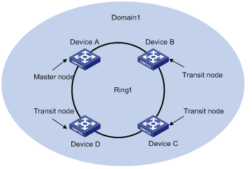
There is only a single ring in the network topology. In this case, you only need to define an RRPP domain.
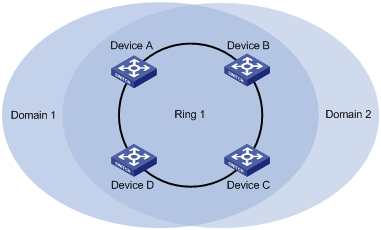
Tangent rings
There are two or more rings in the network topology and only one common node between rings. In this case, you need define an RRPP domain for each ring.
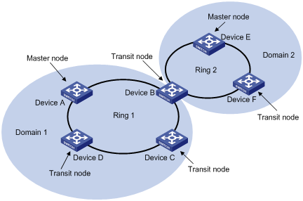
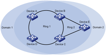
Intersecting rings
Figure 1-4 Intersecting rings
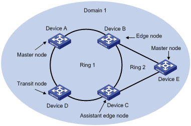
There are two or more rings in the network topology and two common nodes between rings. In this case, you only need to define an RRPP domain, and set one ring as the primary ring and other rings as subrings.
Dual homed rings
Single-ring load balancing
Figure 1-6 Network diagram for single-ring load balancing
In a single-ring network, you can achieve load balancing by configuring multiple domains.
As shown in Figure 1-6, Ring 1 is configured as the primary ring of both Domain 1 and Domain 2. In Domain 1, Device A is configured as the master node of Ring 1; in Domain 2, Device B is configured as the master node of Ring 1. Such configurations enable the ring to block different links based on VLANs, thus achieving single-ring load balancing.
Intersecting-ring load balancing
Figure 1-7 Network diagram for intersecting-ring load balancing
In an intersecting-ring network, you can also achieve load balancing by configuring multiple domains.
As shown in Figure 1-7, Ring 1 is the primary ring and Ring 2 is the subring in both Domain 1 and Domain 2. Domain 1 and Domain 2 are configured with different protected VLANs. Device A is configured as the master node of Ring 1 in Domain 1; Device D is configured as the master node of Ring 1 in Domain 2. Device E is configured as the master node of Ring 2 in both Domain 1 and Domain 2. However, different ports on Device E are blocked in Domain 1 and Domain 2. After such configurations, you can enable traffic of different VLANs to travel over different paths in the subring and primary ring, thus achieving intersecting-ring load balancing.
Protocols and Standards
RFC 3619 is related to RRPP.
RRPP Configuration Task List
![]()
l RRPP does not have an auto election mechanism, so you must configure each node in the ring network properly for RRPP to monitor and protect the ring network.
l Before configuring RRPP, you need to construct a ring-shaped Ethernet topology physically.
You can create RRPP domains based on service planning, specify control VLANs and data VLANs for each RRPP domain, and then determine the ring roles and node roles based on the traffic paths in each RRPP domain. You can configure devices through the following configurations.
Complete the following tasks to configure RRPP:
|
Task |
Description |
|
Required |
|
|
Optional |
|
|
Optional |
|
|
Optional |
|
|
Optional To reduce Edge-Hello traffic, you can adopt the ring group mechanism, that is, assign subrings with the same edge node/assistant-edge node to a ring group. |
![]()
l It is recommended to configure the primary ring first and then the subring when you configure an RRPP domain. Moreover, a Ring ID cannot be applied to more than one RRPP ring in one RRPP domain.
l If a device lies on multiple RRPP rings in an RRPP domain, only one primary ring exists. The device serves as either an edge node or an assistant edge node on the subrings.
l The total number of rings configured on a device in all RRPP domains cannot be greater than 16.
l Modification of node mode, port role and ring level of an RRPP ring is prohibited after configuration. If needed, you must first delete the existing configuration.
l During load balancing configuration, different protected VLANs must be configured for different domains.
Ports connected to an RRPP ring must conform to the following conditions:
l The link type of these ports must be trunk.
l They must be Layer 2 Ethernet ports, Layer 2 GE ports or Layer 2 aggregate ports,.
l They must not be member ports of any aggregation group, service loopback group, or smart link group.
l STP, 802.1x, MAC address authentication and Voice VLAN are all disabled on them.
l Do not enable OAM remote loopback function on an RRPP port. Otherwise, this may cause temporary broadcast storm.
l Enable link status rapid report function on a port accessing an RRPP ring (the link-delay of the port is set to 0) to accelerate topology convergence.
![]()
l If you need to transparently transmit RRPP packets on a device without enabling RRPP, you must ensure only the two ports accessing an RRPP ring permit the packets of the control VLAN. Otherwise, the packets from other VLANs may go into the control VLAN in transparent transmission mode and strike the RRPP ring.
l Do not configure the default VLAN of a port accessing an RRPP ring as the primary control VLAN or the secondary control VLAN, ensuring proper receiving/sending of RRPP packets.
l Do not enable QinQ or VLAN mapping on the control VLAN. Otherwise, RRPPDUs cannot be forwarded properly.
l You can still assign ports to or remove ports from the aggregation group corresponding to a Layer 2 aggregate port configured as an RRPP port.
Configuring Master Node
Follow these steps to configure master node:
|
To do… |
Use the command… |
Remarks |
|
Enter system view |
system-view |
— |
|
Create an RRPP domain and enter its view |
rrpp domain domain-id |
Required |
|
Specify control VLAN for the RRPP domain |
control-vlan vlan-id |
Required |
|
Specify the protected VLANs for the RRPP domain |
protected-vlan reference-instance instance-id-list |
Required No protected VLAN is specified for an RRPP domain by default. |
|
Specify the current device as the master node of the ring, and specify the primary port and the secondary port |
ring ring-id node-mode master [ primary-port interface-type interface-number ] [ secondary-port interface-type interface-number ] level level-value |
Required |
|
Configure the timer for the RRPP domain |
timer hello-timer hello-value fail-timer fail-value |
Optional By default, the Hello timer value is 1 second and the Fail timer value is 3 seconds. |
|
Enable the RRPP ring |
ring ring-id enable |
Required By default, the RRPP ring is disabled. |
|
Return to system view |
quit |
— |
|
Enable RRPP |
rrpp enable |
Required By default, RRPP is disabled. |
![]()
l Before specifying RRPP rings for an RRPP domain, you must specify protected VLANs for the domain.
l Before specifying rings for an RRPP domain, you can delete or modify the protected VLANs configured for the RRPP domain; after specifying rings for an RRPP domain, you can delete or modify the protected VLANs configured for the RRPP domain, however, you cannot delete all the protected VLANs configured for the domain.
l Deleting an RRPP domain deletes its protected VLANs at the same time.
l The protected-vlan command configures protected VLANs for an RRPP domain by referencing MSTIs to which the protected VLANs are mapped. You can use the display stp region-configuration command to view the VLAN-to-MSTI mappings. For detailed information about VLAN-to-MSTI mapping configuration, refer to MSTP Configuration in the Access Volume.
l The control VLAN configured for an RRPP domain must be a new one.
l Control VLAN configuration is required for configuring an RRPP ring.
l To use the undo rrpp domain command to remove an RRPP domain, you must ensure the RRPP domain has no RRPP ring.
l Before removing or modifying the control VLAN of an RRPP domain, make sure that the RRPP domain is not configured with any RRPP ring.
Configuring Transit Node
Follow these steps to configure transit node:
|
To do… |
Use the command… |
Remarks |
|
Enter system view |
system-view |
— |
|
Create an RRPP domain and enter its view |
rrpp domain domain-id |
Required |
|
Specify a control VLAN for the RRPP domain |
control-vlan vlan-id |
Required |
|
Specify protected VLANs for the RRPP domain |
protected-vlan reference-instance instance-id-list |
Required No protected VLAN is specified for an RRPP domain by default. |
|
Specify the current device as the transit node of the ring, and specify the primary port and the secondary port |
ring ring-id node-mode transit [ primary-port interface-type interface-number ] [ secondary-port interface-type interface-number ] level level-value |
Required |
|
Enable the RRPP ring |
ring ring-id enable |
Required By default, the RRPP ring is disabled. |
|
Return to system view |
quit |
— |
|
Enable RRPP |
rrpp enable |
Required By default, RRPP is disabled. |
![]()
l Before specifying RRPP rings for an RRPP domain, you must specify protected VLANs for the domain.
l Before specifying rings for an RRPP domain, you can delete or modify the protected VLANs configured for the RRPP domain; after specifying rings for an RRPP domain, you can delete or modify the protected VLANs configured for the RRPP domain, however, you cannot delete all the protected VLANs configured for the domain.
l Deleting an RRPP domain deletes its protected VLANs at the same time.
l The protected-vlan command configures protected VLANs for an RRPP domain by referencing MSTIs to which the protected VLANs are mapped. You can use the display stp region-configuration command to view the VLAN-to-MSTI mappings. For detailed information about VLAN-to-MSTI mapping configuration, refer to MSTP Configuration in the Access Volume.
l The control VLAN configured for an RRPP domain must be a new one.
l Control VLAN configuration is required for configuring an RRPP ring.
l To use the undo rrpp domain command to remove an RRPP domain, you must ensure the RRPP domain has no RRPP ring.
l Before removing or modifying the control VLAN of an RRPP domain, make sure that the RRPP domain is not configured with any RRPP ring.
Configuring Edge Node
Follow these steps to configure edge node:
|
To do… |
Use the command… |
Remarks |
|
Enter system view |
system-view |
— |
|
Create an RRPP domain and enter its view |
rrpp domain domain-id |
Required |
|
Specify a control VLAN for the RRPP domain |
control-vlan vlan-id |
Required |
|
Specify protected VLANs for the RRPP domain |
protected-vlan reference-instance instance-id-list |
Required No protected VLAN is specified for an RRPP domain by default. |
|
Specify the current device as the transit node of the primary ring, and specify the primary port and the secondary port |
ring ring-id node-mode transit [ primary-port interface-type interface-number ] [ secondary-port interface-type interface-number ] level level-value |
Required |
|
Specify the current device as the edge node of a subring, and specify the edge port |
ring ring-id node-mode edge [ edge-port interface-type interface-number ] |
Required |
|
Enable the primary ring |
ring ring-id enable |
Required By default, the RRPP ring is disabled. |
|
Enable the subring |
ring ring-id enable |
Required By default, the RRPP ring is disabled. |
|
Return to system view |
quit |
— |
|
Enable RRPP |
rrpp enable |
Required By default, RRPP is disabled. |
![]()
l Before specifying RRPP rings for an RRPP domain, you must specify protected VLANs for the domain.
l Before specifying rings for an RRPP domain, you can delete or modify the protected VLANs configured for the RRPP domain; after specifying rings for an RRPP domain, you can delete or modify the protected VLANs configured for the RRPP domain, however, you cannot delete all the protected VLANs configured for the domain.
l Deleting an RRPP domain deletes its protected VLANs at the same time.
l The protected-vlan command configures protected VLANs for an RRPP domain by referencing MSTIs to which the protected VLANs are mapped. You can use the display stp region-configuration command to view the VLAN-to-MSTI mappings. For detailed information about VLAN-to-MSTI mapping configuration, refer to MSTP Configuration in the Access Volume.
l The control VLAN configured for an RRPP domain must be a new one.
l Control VLAN configuration is required for configuring an RRPP ring.
l A Ring ID cannot be applied to more than one RRPP ring in an RRPP domain.
l You must first configure the primary ring and then the subring when configuring an edge node. Moreover, you must remove all subring configurations before deleting the primary ring configuration of an edge node. However, the RRPP ring enabled cannot be deleted.
l To use the undo rrpp domain command to remove an RRPP domain, you must ensure the RRPP domain has no RRPP ring.
l Before removing or modifying the control VLAN of an RRPP domain, make sure that the RRPP domain is not configured with any RRPP ring.
Configuring Assistant Edge Node
Follow these steps to configure assistant edge node:
|
To do… |
Use the command… |
Remarks |
|
Enter system view |
system-view |
— |
|
Create an RRPP domain and enter its view |
rrpp domain domain-id |
Required |
|
Specify a control VLAN for the RRPP domain |
control-vlan vlan-id |
Required |
|
Specify protected VLANs for the RRPP domain |
protected-vlan reference-instance instance-id-list |
Required No protected VLAN is specified for an RRPP domain by default. |
|
Specify the current device as the transit node of the primary ring, and specify the primary port and the secondary port |
ring ring-id node-mode transit [ primary-port interface-type interface-number ] [ secondary-port interface-type interface-number ] level level-value |
Required |
|
Specify the current device as the assistant edge node of the subring, and specify an edge port |
ring ring-id node-mode assistant-edge [ edge-port interface-type interface-number ] |
Required |
|
Enable the primary ring |
ring ring-id enable |
Required By default, the RRPP ring is disabled. |
|
Enable the subring |
ring ring-id enable |
Required By default, the RRPP ring is disabled. |
|
Return to system view |
quit |
— |
|
Enable RRPP |
rrpp enable |
Required By default, RRPP is disabled. |
![]()
l Before specifying RRPP rings for an RRPP domain, you must specify protected VLANs for the domain.
l Before specifying rings for an RRPP domain, you can delete or modify the protected VLANs configured for the RRPP domain; after specifying rings for an RRPP domain, you can delete or modify the protected VLANs configured for the RRPP domain, however, you cannot delete all the protected VLANs configured for the domain.
l Deleting an RRPP domain deletes its protected VLANs at the same time.
l The protected-vlan command configures protected VLANs for an RRPP domain by referencing MSTIs to which the protected VLANs are mapped. You can use the display stp region-configuration command to view the VLAN-to-MSTI mappings. For detailed information about VLAN-to-MSTI mapping configuration, refer to MSTP Configuration in the Access Volume.
l The control VLAN configured for an RRPP domain must be a new one.
l Control VLAN configuration is required for configuring an RRPP ring.
l A Ring ID cannot be applied to more than one RRPP ring in an RRPP domain.
l You must first configure the primary ring and then the subring when configuring an edge node. Moreover, you must remove all subring configurations before deleting the primary ring configuration of an edge node. However, the RRPP ring enabled cannot be deleted.
l To use the undo rrpp domain command to remove an RRPP domain, you must ensure the RRPP domain has no RRPP ring.
l Before removing or modifying the control VLAN of an RRPP domain, make sure that the RRPP domain is not configured with any RRPP ring.
Configuring Ring Group
To reduce Edge-Hello traffic, you can adopt the ring group mechanism, that is, assign subrings with the same edge node/assistant-edge node to a ring group.
You need to configure ring groups on both the edge node and the assistant-edge node at the same time. The two ring groups must be configured with the same subrings. Otherwise, the ring groups cannot operate properly.
Configuration Prerequisites
l The RRPP domain, control VLANs, protected VLANs, the primary ring, and the subrings have been configured on the edge node device.
l The RRPP domain, control VLANs, protected VLANs, the primary ring, and the subrings have been configured on the assistant-edge node device.
Configuring Ring Group
Follow these steps to configure a ring group:
|
To do… |
Use the command… |
Remarks |
|
Enter system view |
system-view |
— |
|
Create a ring group and enter ring group view |
rrpp ring-group ring-group-id |
Required |
|
Assign the specified subrings to the ring group |
domain domain-id ring ring-id-list |
Required |
![]()
l To add an activated ring to a ring group, first add the ring to the assistant-edge node ring group and then to the edge node ring group.
l To remove a ring from a ring group, first remove the ring from the edge node ring group and then from the assistant-edge node group.
l To remove a ring group, first remove the edge node ring group and then the assistant-edge node ring group.
l To activate the rings in a ring group, first activate the rings in the assistant-edge node ring group and then the rings in the edge node ring group.
l To deactivate the rings in a ring group, first deactivate the rings in the edge node ring group and then the rings in the assistant-edge node ring group.
l If you do not following the orders above, the assistant-edge node may take the primary ring as failed because the assistant-edge node cannot receive Edge-Hello packets.
Displaying and Maintaining RRPP
|
To do… |
Use the command… |
Remarks |
|
Display brief information about RRPP configuration |
display rrpp brief |
Available in any view |
|
Display detailed information about RRPP configuration |
display rrpp verbose domain domain-id [ ring ring-id ] |
|
|
Display RRPP statistics |
display rrpp statistics domain domain-id [ ring ring-id ] |
|
|
Clear RRPP statistics |
reset rrpp statistics domain domain-id [ ring ring-id ] |
Available in user view |
RRPP Typical Configuration Examples
This section covers these topics:
l Configuring Single Ring Topology
l Configuring Intersecting Ring Topology
l Configuring Intersecting-Ring Load Balancing
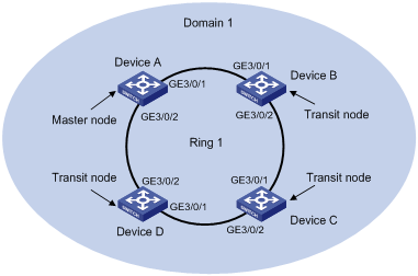
Configuring Single Ring Topology
Networking requirements
l Device A, Device B, Device C and Device D constitute RRPP domain 1;
l Specify the control VLAN of RRPP domain 1 as VLAN 4092;
l RPPP domain 1 protects all VLANs;
l Device A, Device B, Device C and Device D constitute primary ring 1;
l Specify Device A as the master node of primary ring 1, GigabitEthernet 3/0/1 as the primary port and GigabitEthernet 3/0/2 as the secondary port;
l Specify Device B, Device C and Device D as the transit nodes of primary ring 1, their GigabitEthernet 3/0/1 as the primary port and GigabitEthernet 3/0/2 as the secondary port;
l The timers of the primary ring adopt the default value.
Figure 1-8 Single ring networking diagram
Configuration considerations
First, determine the node mode of a device in an RRPP ring, and then perform the following configurations on a per-device basis:
l Disable STP on all ports accessing RRPP rings on these devices and configure these ports to permit the traffic of all VLANs to pass through.
l Create an RRPP domain.
l Specify the control VLAN for the RRPP domain.
l Configure the MSTIs referenced by the protected VLANs.
l Specify the node mode of a device on the primary ring and the ports accessing the RRPP ring on the device.
l Enable the RRPP ring.
l Enable RRPP.
Configuration procedure
1) Perform the following configuration on Device A:
<DeviceA> system-view
[DeviceA] interface gigabitethernet 3/0/1
[DeviceA-GigabitEthernet3/0/1] link-delay 0
[DeviceA-GigabitEthernet3/0/1] stp disable
[DeviceA-GigabitEthernet3/0/1] port link-type trunk
[DeviceA-GigabitEthernet3/0/1] port trunk permit vlan all
[DeviceA-GigabitEthernet3/0/1] quit
[DeviceA] interface gigabitethernet 3/0/2
[DeviceA-GigabitEthernet3/0/2] link-delay 0
[DeviceA-GigabitEthernet3/0/2] stp disable
[DeviceA-GigabitEthernet3/0/2] port link-type trunk
[DeviceA-GigabitEthernet3/0/2] port trunk permit vlan all
[DeviceA-GigabitEthernet3/0/2] quit
[DeviceA] rrpp domain 1
[DeviceA-rrpp-domain1] control-vlan 4092
[DeviceA-rrpp-domain1] protected-vlan reference-instance 0 to 31
[DeviceA-rrpp-domain1] ring 1 node-mode master primary-port gigabitethernet 3/0/1 secondary-port gigabitethernet 3/0/2 level 0
[DeviceA-rrpp-domain1] ring 1 enable
[DeviceA-rrpp-domain1] quit
[DeviceA] rrpp enable
2) Perform the following configuration on Device B:
<DeviceB> system-view
[DeviceB] interface gigabitethernet 3/0/1
[DeviceB-GigabitEthernet3/0/1] link-delay 0
[DeviceB-GigabitEthernet3/0/1] stp disable
[DeviceB-GigabitEthernet3/0/1] port link-type trunk
[DeviceB-GigabitEthernet3/0/1] port trunk permit vlan all
[DeviceB-GigabitEthernet3/0/1] quit
[DeviceB] interface gigabitethernet 3/0/2
[DeviceB-GigabitEthernet3/0/2] link-delay 0
[DeviceB-GigabitEthernet3/0/2] stp disable
[DeviceB-GigabitEthernet3/0/2] port link-type trunk
[DeviceB-GigabitEthernet3/0/2] port trunk permit vlan all
[DeviceB-GigabitEthernet3/0/2] quit
[DeviceB] rrpp domain 1
[DeviceB-rrpp-domain1] control-vlan 4092
[DeviceB-rrpp-domain1] protected-vlan reference-instance 0 to 31
[DeviceB-rrpp-domain1] ring 1 node-mode transit primary-port gigabitethernet 3/0/1 secondary-port gigabitethernet 3/0/2 level 0
[DeviceB-rrpp-domain1] ring 1 enable
[DeviceB-rrpp-domain1] quit
[DeviceB] rrpp enable
3) Perform the following configuration on Device C:
<DeviceC> system-view
[DeviceC] interface gigabitethernet 3/0/1
[DeviceC-GigabitEthernet3/0/1] link-delay 0
[DeviceC-GigabitEthernet3/0/1] stp disable
[DeviceC-GigabitEthernet3/0/1] port link-type trunk
[DeviceC-GigabitEthernet3/0/1] port trunk permit vlan all
[DeviceC-GigabitEthernet3/0/1] quit
[DeviceC] interface gigabitethernet 3/0/2
[DeviceC-GigabitEthernet3/0/2] link-delay 0
[DeviceC-GigabitEthernet3/0/2] stp disable
[DeviceC-GigabitEthernet3/0/2] port link-type trunk
[DeviceC-GigabitEthernet3/0/2] port trunk permit vlan all
[DeviceC-GigabitEthernet3/0/2] quit
[DeviceC] rrpp domain 1
[DeviceC-rrpp-domain1] control-vlan 4092
[DeviceC-rrpp-domain1] protected-vlan reference-instance 0 to 31
[DeviceC-rrpp-domain1] ring 1 node-mode transit primary-port gigabitethernet 3/0/1 secondary-port gigabitethernet 3/0/2 level 0
[DeviceC-rrpp-domain1] ring 1 enable
[DeviceC-rrpp-domain1] quit
[DeviceC] rrpp enable
4) Perform the following configuration on Device D:
<DeviceD> system-view
[DeviceD] interface gigabitethernet 3/0/1
[DeviceD-GigabitEthernet3/0/1] link-delay 0
[DeviceD-GigabitEthernet3/0/1] stp disable
[DeviceD-GigabitEthernet3/0/1] port link-type trunk
[DeviceD-GigabitEthernet3/0/1] port trunk permit vlan all
[DeviceD-GigabitEthernet3/0/1] quit
[DeviceD] interface gigabitethernet 3/0/2
[DeviceD-GigabitEthernet3/0/2] link-delay 0
[DeviceD-GigabitEthernet3/0/2] stp disable
[DeviceD-GigabitEthernet3/0/2] port link-type trunk
[DeviceD-GigabitEthernet3/0/2] port trunk permit vlan all
[DeviceD-GigabitEthernet3/0/2] quit
[DeviceD] rrpp domain 1
[DeviceD-rrpp-domain1] control-vlan 4092
[DeviceD-rrpp-domain1] protected-vlan reference-instance 0 to 31
[DeviceD-rrpp-domain1] ring 1 node-mode transit primary-port gigabitethernet 3/0/1 secondary-port gigabitethernet 3/0/2 level 0
[DeviceD-rrpp-domain1] ring 1 enable
[DeviceD-rrpp-domain1] quit
[DeviceD] rrpp enable
After the above configuration, you can use the display command to view RRPP configuration.
Configuring Single-Domain Intersecting Ring Topology
Networking requirements
l Device A, Device B, Device C and Device D constitute RRPP domain 1.
l VLAN 4092 is the control VLAN of RRPP domain 1;
l RRPP domain 1 protects all the VLANs;
l Device A, Device B, Device C and Device D constitute primary ring 1;
l Device B, Device C and Device E constitute subring 2;
l Device A is the master node of primary ring 1, GigabitEthernet 3/0/1 is the primary port and GigabitEthernet 3/0/2 is the secondary port;
l Device E is the master node of subring 2, GigabitEthernet 3/0/1 is the primary port and GigabitEthernet 3/0/2 is the secondary port;
l Device B is the transit node of primary ring 1 and the edge node of subring 2, and GigabitEthernet 3/0/3 is the edge port;
l Device C is the transit node of primary ring 1 and the assistant edge node of subring 1, and GigabitEthernet 3/0/3 is the edge port;
l Device D is the transit node of primary ring 1, GigabitEthernet 3/0/1 is the primary port and GigabitEthernet 3/0/2 is the secondary port;
l The timers of both the primary ring and the subring adopt the default value.
Figure 1-9 Networking diagram for intersecting rings configuration
Configuration considerations
First, determine the primary ring and subring in an RRPP domain, node mode of a device on each RRPP ring, and then perform the following configuration on a per-device basis:
l Disable STP on all ports accessing RRPP rings on these devices and configure these ports to permit the traffic of all VLANs to pass through.
l Create an RRPP domain.
l Specify the control VLAN for the RRPP domain.
l Configure the protected VLANs to reference all MSTIs.
l Specify the node mode of a device on an RRPP ring and the ports accessing the RRPP ring on the device.
l Enable these two RRPP rings.
l Enable RRPP
Configuration procedure
1) Configuration on Device A
<DeviceA> system-view
[DeviceA] interface gigabitethernet 3/0/1
[DeviceA-GigabitEthernet3/0/1] link-delay 0
[DeviceA-GigabitEthernet3/0/1] stp disable
[DeviceA-GigabitEthernet3/0/1] port link-type trunk
[DeviceA-GigabitEthernet3/0/1] port trunk permit vlan all
[DeviceA-GigabitEthernet3/0/1] quit
[DeviceA] interface gigabitethernet 3/0/2
[DeviceA-GigabitEthernet3/0/2] link-delay 0
[DeviceA-GigabitEthernet3/0/2] stp disable
[DeviceA-GigabitEthernet3/0/2] port link-type trunk
[DeviceA-GigabitEthernet3/0/2] port trunk permit vlan all
[DeviceA-GigabitEthernet3/0/2] quit
[DeviceA] rrpp domain 1
[DeviceA-rrpp-domain1] control-vlan 4092
[DeviceA-rrpp-domain1] protected-vlan reference-instance 0 to 31
[DeviceA-rrpp-domain1] ring 1 node-mode master primary-port gigabitethernet 3/0/1 secondary-port gigabitethernet 3/0/2 level 0
[DeviceA-rrpp-domain1] ring 1 enable
[DeviceA-rrpp-domain1] quit
[DeviceA] rrpp enable
2) Configuration on Device B
<DeviceB> system-view
[DeviceB] interface gigabitethernet 3/0/1
[DeviceB-GigabitEthernet3/0/1] link-delay 0
[DeviceB-GigabitEthernet3/0/1] stp disable
[DeviceB-GigabitEthernet3/0/1] port link-type trunk
[DeviceB-GigabitEthernet3/0/1] port trunk permit vlan all
[DeviceB-GigabitEthernet3/0/1] quit
[DeviceB] interface gigabitethernet 3/0/2
[DeviceB-GigabitEthernet3/0/2] link-delay 0
[DeviceB-GigabitEthernet3/0/2] stp disable
[DeviceB-GigabitEthernet3/0/2] port link-type trunk
[DeviceB-GigabitEthernet3/0/2] port trunk permit vlan all
[DeviceB-GigabitEthernet3/0/2] quit
[DeviceB] interface gigabitethernet 3/0/3
[DeviceB-GigabitEthernet3/0/3] link-delay 0
[DeviceB-GigabitEthernet3/0/3] stp disable
[DeviceB-GigabitEthernet3/0/3] port link-type trunk
[DeviceB-GigabitEthernet3/0/3] port trunk permit vlan all
[DeviceB-GigabitEthernet3/0/3] quit
[DeviceB] rrpp domain 1
[DeviceB-rrpp-domain1] control-vlan 4092
[DeviceB-rrpp-domain1] protected-vlan reference-instance 0 to 31
[DeviceB-rrpp-domain1] ring 1 node-mode transit primary-port gigabitethernet 3/0/1 secondary-port gigabitethernet 3/0/2 level 0
[DeviceB-rrpp-domain1] ring 2 node-mode edge edge-port gigabitethernet 3/0/3
[DeviceB-rrpp-domain1] ring 1 enable
[DeviceB-rrpp-domain1] ring 2 enable
[DeviceB-rrpp-domain1] quit
[DeviceB] rrpp enable
3) Configuration on Device C
<DeviceC> system-view
[DeviceC] interface gigabitethernet 3/0/1
[DeviceC-GigabitEthernet3/0/1] link-delay 0
[DeviceC-GigabitEthernet3/0/1] stp disable
[DeviceC-GigabitEthernet3/0/1] port link-type trunk
[DeviceC-GigabitEthernet3/0/1] port trunk permit vlan all
[DeviceC-GigabitEthernet3/0/1] quit
[DeviceC] interface gigabitethernet 3/0/2
[DeviceC-GigabitEthernet3/0/2] link-delay 0
[DeviceC-GigabitEthernet3/0/2] stp disable
[DeviceC-GigabitEthernet3/0/2] port link-type trunk
[DeviceC-GigabitEthernet3/0/2] port trunk permit vlan all
[DeviceC-GigabitEthernet3/0/2] quit
[DeviceC] interface gigabitethernet 3/0/3
[DeviceC-GigabitEthernet3/0/3] link-delay 0
[DeviceC-GigabitEthernet3/0/3] stp disable
[DeviceC-GigabitEthernet3/0/3] port link-type trunk
[DeviceC-GigabitEthernet3/0/3] port trunk permit vlan all
[DeviceC-GigabitEthernet3/0/3] quit
[DeviceC] rrpp domain 1
[DeviceC-rrpp-domain1] control-vlan 4092
[DeviceC-rrpp-domain1] protected-vlan reference-instance 0 to 31
[DeviceC-rrpp-domain1] ring 1 node-mode transit primary-port gigabitethernet 3/0/1 secondary-port gigabitethernet 3/0/2 level 0
[DeviceC-rrpp-domain1] ring 2 node-mode assistant-edge edge-port gigabitethernet 3/0/3
[DeviceC-rrpp-domain1] ring 1 enable
[DeviceC-rrpp-domain1] ring 2 enable
[DeviceC-rrpp-domain1] quit
[DeviceC] rrpp enable
4) Configuration on Device D
<DeviceD> system-view
[DeviceD] interface gigabitethernet 3/0/1
[DeviceD-GigabitEthernet3/0/1] link-delay 0
[DeviceD-GigabitEthernet3/0/1] stp disable
[DeviceD-GigabitEthernet3/0/1] port link-type trunk
[DeviceD-GigabitEthernet3/0/1] port trunk permit vlan all
[DeviceD-GigabitEthernet3/0/1] quit
[DeviceD] interface gigabitethernet 3/0/2
[DeviceD-GigabitEthernet3/0/2] link-delay 0
[DeviceD-GigabitEthernet3/0/2] stp disable
[DeviceD-GigabitEthernet3/0/2] port link-type trunk
[DeviceD-GigabitEthernet3/0/2] port trunk permit vlan all
[DeviceD-GigabitEthernet3/0/2] quit
[DeviceD] rrpp domain 1
[DeviceD-rrpp-domain1] control-vlan 4092
[DeviceD-rrpp-domain1] protected-vlan reference-instance 0 to 31
[DeviceD-rrpp-domain1] ring 1 node-mode transit primary-port gigabitethernet 3/0/1 secondary-port gigabitethernet 3/0/2 level 0
[DeviceD-rrpp-domain1] ring 1 enable
[DeviceD-rrpp-domain1] quit
[DeviceD] rrpp enable
5) Configuration on Device E
<DeviceE> system-view
[DeviceE] interface gigabitethernet 3/0/1
[DeviceE-GigabitEthernet3/0/1] link-delay 0
[DeviceE-GigabitEthernet3/0/1] stp disable
[DeviceE-GigabitEthernet3/0/1] port link-type trunk
[DeviceE-GigabitEthernet3/0/1] port trunk permit vlan all
[DeviceE-GigabitEthernet3/0/1] quit
[DeviceE] interface gigabitethernet 3/0/2
[DeviceE-GigabitEthernet3/0/2] link-delay 0
[DeviceE-GigabitEthernet3/0/2] stp disable
[DeviceE-GigabitEthernet3/0/2] port link-type trunk
[DeviceE-GigabitEthernet3/0/2] port trunk permit vlan all
[DeviceE-GigabitEthernet3/0/2] quit
[DeviceE] rrpp domain 1
[DeviceE-rrpp-domain1] control-vlan 4092
[DeviceE-rrpp-domain1] protected-vlan reference-instance 0 to 31
[DeviceE-rrpp-domain1] ring 2 node-mode master primary-port gigabitethernet 3/0/1 secondary-port gigabitethernet 3/0/2 level 1
[DeviceE-rrpp-domain1] ring 2 enable
[DeviceE-rrpp-domain1] quit
[DeviceE] rrpp enable
After the configuration, you can use the display command to view RRPP configuration result.
Configuring Intersecting-Ring Load Balancing
Networking requirements
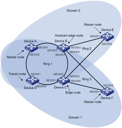
l Device A, Device B, Device C, Device D, and Device F constitute RRPP domain 1, and VLAN 100 is the control VLAN of the RRPP domain. Device A is the master node of the primary ring Ring 1; Device D is the transit node of the primary ring Ring 1; Device F is the master node of the subring Ring 3; Device C is the edge node of the subring Ring 3; Device B is the assistant-edge node of the subring Ring 3.
l Device A, Device B, Device C, Device D, and Device E constitute RRPP domain 2, and VLAN 105 is the control VLAN of the RRPP domain. Device A is the master node of the primary ring Ring 1; Device D is the transit node of the primary ring Ring 1; Device E is the master node of the subring Ring 2; Device C is the edge node of the subring Ring 2; Device B is the assistant-edge node of the subring Ring 2.
l Specify VLAN 10 as the protected VLAN of domain 1, and VLAN 20 as the protected VLAN of domain 2. Thus, you can achieve VLAN-based load balancing on the primary ring.
l As the edge node and assistant-edge node of subring Ring 2 is the same as those of subring Ring 3, and the two subrings have the same link in the primary ring, you can add subrings Ring 2 and Ring 3 to the ring group to reduce Edge-Hello traffic.
Figure 1-10 Network diagram for intersecting-ring load balancing
Configuration considerations
l Create data VLANs, and map the VLANs to be protected in each RRPP domain to different MSTIs.
l Disable STP on all ports accessing RRPP rings on these devices and configure the VLANs whose traffic is permitted to pass through.
l Create RRPP domains.
l Specify control VLANs for RRPP domains.
l Specify protected VLANs for each domain by specifying MSTIs.
l Specify the roles of devices in these RRPP rings and the ports accessing RRPP rings.
l Enable RRPP rings.
l Enable the RRPP protocol.
l Configure a ring group on the edge nodes and assistant-edge nodes.
Configuration procedure
1) Configure Device A as the master node of the primary ring
<DeviceA> system-view
[DeviceA] vlan 10
[DeviceA-vlan10] quit
[DeviceA] vlan 20
[DeviceA-vlan20] quit
[DeviceA] stp region-configuration
[DeviceA-mst-region] instance 1 vlan 10
[DeviceA-mst-region] instance 2 vlan 20
[DeviceA-mst-region] active region-configuration
[DeviceA-mst-region] quit
[DeviceA] interface gigabitethernet 3/0/1
[DeviceA-GigabitEthernet3/0/1] link-delay 0
[DeviceA-GigabitEthernet3/0/1] stp disable
[DeviceA-GigabitEthernet3/0/1] port link-type trunk
[DeviceA-GigabitEthernet3/0/1] undo port trunk permit vlan 1
[DeviceA-GigabitEthernet3/0/1] port trunk permit vlan 10 20
[DeviceA-GigabitEthernet3/0/1] quit
[DeviceA] interface gigabitethernet 3/0/2
[DeviceA-GigabitEthernet3/0/2] link-delay 0
[DeviceA-GigabitEthernet3/0/2] stp disable
[DeviceA-GigabitEthernet3/0/2] port link-type trunk
[DeviceA-GigabitEthernet3/0/2] undo port trunk permit vlan 1
[DeviceA-GigabitEthernet3/0/2] port trunk permit vlan 10 20
[DeviceA-GigabitEthernet3/0/2] quit
[DeviceA] rrpp domain 1
[DeviceA-rrpp-domain1] control-vlan 100
[DeviceA-rrpp-domain1] protected-vlan reference-instance 1
[DeviceA-rrpp-domain1] ring 1 node-mode master primary-port gigabitethernet 3/0/1 secondary-port gigabitethernet 3/0/2 level 0
[DeviceA-rrpp-domain1] ring 1 enable
[DeviceA-rrpp-domain1] quit
[DeviceA] rrpp domain 2
[DeviceA-rrpp-domain2] control-vlan 105
[DeviceA-rrpp-domain2] protected-vlan reference-instance 2
[DeviceA-rrpp-domain2] ring 1 node-mode master primary-port gigabitethernet 3/0/2 secondary-port gigabitethernet 3/0/1 level 0
[DeviceA-rrpp-domain2] ring 1 enable
[DeviceA-rrpp-domain2] quit
[DeviceA] rrpp enable
2) Configure Device B as the assistant-edge node of subrings Ring 2 and Ring 3
<DeviceB> system-view
[DeviceB] vlan 10
[DeviceB-vlan10] quit
[DeviceB] vlan 20
[DeviceB-vlan20] quit
[DeviceB] stp region-configuration
[DeviceB-mst-region] instance 1 vlan 10
[DeviceB-mst-region] instance 2 vlan 20
[DeviceB-mst-region] active region-configuration
[DeviceB-mst-region] quit
[DeviceB] interface gigabitethernet 3/0/1
[DeviceB-GigabitEthernet3/0/1] link-delay 0
[DeviceB-GigabitEthernet3/0/1] stp disable
[DeviceB-GigabitEthernet3/0/1] port link-type trunk
[DeviceB-GigabitEthernet3/0/1] undo port trunk permit vlan 1
[DeviceB-GigabitEthernet3/0/1] port trunk permit vlan 10 20
[DeviceB-GigabitEthernet3/0/1] quit
[DeviceB] interface gigabitethernet 3/0/2
[DeviceB-GigabitEthernet3/0/2] link-delay 0
[DeviceB-GigabitEthernet3/0/2] stp disable
[DeviceB-GigabitEthernet3/0/2] port link-type trunk
[DeviceB-GigabitEthernet3/0/2] undo port trunk permit vlan 1
[DeviceB-GigabitEthernet3/0/2] port trunk permit vlan 10 20
[DeviceB-GigabitEthernet3/0/2] quit
[DeviceB] interface gigabitethernet 3/0/3
[DeviceB-GigabitEthernet3/0/3] link-delay 0
[DeviceB-GigabitEthernet3/0/3] stp disable
[DeviceB-GigabitEthernet3/0/3] port link-type trunk
[DeviceB-GigabitEthernet3/0/3] undo port trunk permit vlan 1
[DeviceB-GigabitEthernet3/0/3] port trunk permit vlan 20
[DeviceB-GigabitEthernet3/0/3] quit
[DeviceB] interface gigabitethernet 3/0/4
[DeviceB-GigabitEthernet3/0/4] link-delay 0
[DeviceB-GigabitEthernet3/0/4] stp disable
[DeviceB-GigabitEthernet3/0/4] port link-type trunk
[DeviceB-GigabitEthernet3/0/4] undo port trunk permit vlan 1
[DeviceB-GigabitEthernet3/0/4] port trunk permit vlan 10
[DeviceB-GigabitEthernet3/0/4] quit
[DeviceB] rrpp domain 1
[DeviceB-rrpp-domain1] control-vlan 100
[DeviceB-rrpp-domain1] protected-vlan reference-instance 1
[DeviceB-rrpp-domain1] ring 1 node-mode transit primary-port gigabitethernet 3/0/1 secondary-port gigabitethernet 3/0/2 level 0
[DeviceB-rrpp-domain1] ring 3 node-mode assistant-edge edge-port gigabitethernet 3/0/4
[DeviceB-rrpp-domain1] ring 1 enable
[DeviceB-rrpp-domain1] ring 3 enable
[DeviceB-rrpp-domain1] quit
[DeviceB] rrpp domain 2
[DeviceB-rrpp-domain2] control-vlan 105
[DeviceB-rrpp-domain2] protected-vlan reference-instance 2
[DeviceB-rrpp-domain2] ring 1 node-mode transit primary-port gigabitethernet 3/0/1
secondary-port gigabitethernet 3/0/2 level 0
[DeviceB-rrpp-domain2] ring 2 node-mode assistant-edge edge-port gigabitethernet 3/0/3
[DeviceB-rrpp-domain2] ring 1 enable
[DeviceB-rrpp-domain2] ring 2 enable
[DeviceB-rrpp-domain2] quit
[DeviceB] rrpp enable
3) Configure Device C as the edge node of subrings Ring 2 and Ring 3
<DeviceC> system-view
[DeviceC] vlan 10
[DeviceC-vlan10] quit
[DeviceC] vlan 20
[DeviceC-vlan20] quit
[DeviceC] stp region-configuration
[DeviceC-mst-region] instance 1 vlan 10
[DeviceC-mst-region] instance 2 vlan 20
[DeviceC-mst-region] active region-configuration
[DeviceC-mst-region] quit
[DeviceC] interface gigabitethernet 3/0/1
[DeviceC-GigabitEthernet3/0/1] link-delay 0
[DeviceC-GigabitEthernet3/0/1] stp disable
[DeviceC-GigabitEthernet3/0/1] port link-type trunk
[DeviceC-GigabitEthernet3/0/1] undo port trunk permit vlan 1
[DeviceC-GigabitEthernet3/0/1] port trunk permit vlan 10 20
[DeviceC-GigabitEthernet3/0/1] quit
[DeviceC] interface gigabitethernet 3/0/2
[DeviceC-GigabitEthernet3/0/2] link-delay 0
[DeviceC-GigabitEthernet3/0/2] stp disable
[DeviceC-GigabitEthernet3/0/2] port link-type trunk
[DeviceC-GigabitEthernet3/0/2] undo port trunk permit vlan 1
[DeviceC-GigabitEthernet3/0/2] port trunk permit vlan 10 20
[DeviceC-GigabitEthernet3/0/2] quit
[DeviceC] interface gigabitethernet 3/0/3
[DeviceC-GigabitEthernet3/0/3] link-delay 0
[DeviceC-GigabitEthernet3/0/3] stp disable
[DeviceC-GigabitEthernet3/0/3] port link-type trunk
[DeviceC-GigabitEthernet3/0/3] undo port trunk permit vlan 1
[DeviceC-GigabitEthernet3/0/3] port trunk permit vlan 20
[DeviceC-GigabitEthernet3/0/3] quit
[DeviceC] interface gigabitethernet 3/0/4
[DeviceC-GigabitEthernet3/0/4] link-delay 0
[DeviceC-GigabitEthernet3/0/4] stp disable
[DeviceC-GigabitEthernet3/0/4] port link-type trunk
[DeviceC-GigabitEthernet3/0/4] undo port trunk permit vlan 1
[DeviceC-GigabitEthernet3/0/4] port trunk permit vlan 10
[DeviceC-GigabitEthernet3/0/4] quit
[DeviceC] rrpp domain 1
[DeviceC-rrpp-domain1] control-vlan 100
[DeviceC-rrpp-domain1] protected-vlan reference-instance 1
[DeviceC-rrpp-domain1] ring 1 node-mode transit primary-port gigabitethernet 3/0/1 secondary-port gigabitethernet 3/0/2 level 0
[DeviceC-rrpp-domain1] ring 3 node-mode edge edge-port gigabitethernet 3/0/4
[DeviceC-rrpp-domain1] ring 1 enable
[DeviceC-rrpp-domain1] ring 3 enable
[DeviceC-rrpp-domain1] quit
[DeviceC] rrpp domain 2
[DeviceC-rrpp-domain2] control-vlan 105
[DeviceC-rrpp-domain2] protected-vlan reference-instance 2
[DeviceC-rrpp-domain2] ring 1 node-mode transit primary-port gigabitethernet 3/0/1
secondary-port gigabitethernet 3/0/2 level 0
[DeviceC-rrpp-domain2] ring 2 node-mode edge edge-port gigabitethernet3/0/3
[DeviceC-rrpp-domain2] ring 1 enable
[DeviceC-rrpp-domain2] ring 2 enable
[DeviceC-rrpp-domain2] quit
[DeviceC] rrpp enable
4) Configure Device D as a transit node of the primary ring
<DeviceD> system-view
[DeviceD] vlan 10
[DeviceD-vlan10] quit
[DeviceD] vlan 20
[DeviceD-vlan20] quit
[DeviceD] stp region-configuration
[DeviceD-mst-region] instance 1 vlan 10
[DeviceD-mst-region] instance 2 vlan 20
[DeviceD-mst-region] active region-configuration
[DeviceD-mst-region] quit
[DeviceD] interface gigabitethernet 3/0/1
[DeviceD-GigabitEthernet3/0/1] link-delay 0
[DeviceD-GigabitEthernet3/0/1] stp disable
[DeviceD-GigabitEthernet3/0/1] port link-type trunk
[DeviceD-GigabitEthernet3/0/1] undo port trunk permit vlan 1
[DeviceD-GigabitEthernet3/0/1] port trunk permit vlan 10 20
[DeviceD-GigabitEthernet3/0/1] quit
[DeviceD] interface gigabitethernet 3/0/2
[DeviceD-GigabitEthernet3/0/2] link-delay 0
[DeviceD-GigabitEthernet3/0/2] stp disable
[DeviceD-GigabitEthernet3/0/2] port link-type trunk
[DeviceD-GigabitEthernet3/0/2] undo port trunk permit vlan 1
[DeviceD-GigabitEthernet3/0/2] port trunk permit vlan 10 20
[DeviceD-GigabitEthernet3/0/2] quit
[DeviceD] rrpp domain 1
[DeviceD-rrpp-domain1] control-vlan 100
[DeviceD-rrpp-domain1] protected-vlan reference-instance 1
[DeviceD-rrpp-domain1] ring 1 node-mode transit primary-port gigabitethernet 3/0/1 secondary-port gigabitethernet 3/0/2 level 0
[DeviceD-rrpp-domain1] ring 1 enable
[DeviceD-rrpp-domain1] quit
[DeviceD] rrpp domain 2
[DeviceD-rrpp-domain2] control-vlan 105
[DeviceD-rrpp-domain2] protected-vlan reference-instance 2
[DeviceD-rrpp-domain2] ring 1 node-mode transit primary-port gigabitethernet 3/0/1 secondary-port gigabitethernet 3/0/2 level 0
[DeviceD-rrpp-domain2] ring 1 enable
[DeviceD-rrpp-domain2] quit
[DeviceD] rrpp enable
5) Configure Device E as the master node of subring Ring 2 in domain 2
<DeviceE> system-view
[DeviceE] vlan 20
[DeviceE-vlan20] quit
[DeviceE] stp region-configuration
[DeviceE-mst-region] instance 2 vlan 20
[DeviceE-mst-region] active region-configuration
[DeviceE-mst-region] quit
[DeviceE] interface gigabitethernet 3/0/1
[DeviceE-GigabitEthernet3/0/1] link-delay 0
[DeviceE-GigabitEthernet3/0/1] stp disable
[DeviceE-GigabitEthernet3/0/1] port link-type trunk
[DeviceE-GigabitEthernet3/0/1] undo port trunk permit vlan 1
[DeviceE-GigabitEthernet3/0/1] port trunk permit vlan 20
[DeviceE-GigabitEthernet3/0/1] quit
[DeviceE] interface gigabitethernet 3/0/2
[DeviceE-GigabitEthernet3/0/2] link-delay 0
[DeviceE-GigabitEthernet3/0/2] stp disable
[DeviceE-GigabitEthernet3/0/2] port link-type trunk
[DeviceE-GigabitEthernet3/0/2] undo port trunk permit vlan 1
[DeviceE-GigabitEthernet3/0/2] port trunk permit vlan 20
[DeviceE-GigabitEthernet3/0/2] quit
[DeviceE] rrpp domain 2
[DeviceE-rrpp-domain2] control-vlan 105
[DeviceE-rrpp-domain2] protected-vlan reference-instance 2
[DeviceE-rrpp-domain2] ring 2 node-mode master primary-port gigabitethernet 3/0/2 secondary-port gigabitethernet 3/0/1 level 1
[DeviceE-rrpp-domain2] ring 2 enable
[DeviceE-rrpp-domain2] quit
[DeviceE] rrpp enable
6) Configure Device F as the master node of subring Ring 3 in domain 1
<DeviceF> system-view
[DeviceF] vlan 10
[DeviceF-vlan10] quit
[DeviceF] stp region-configuration
[DeviceF-mst-region] instance 1 vlan 10
[DeviceF-mst-region] active region-configuration
[DeviceF-mst-region] quit
[DeviceF] interface gigabitethernet 3/0/1
[DeviceF-GigabitEthernet3/0/1] link-delay 0
[DeviceF-GigabitEthernet3/0/1] stp disable
[DeviceF-GigabitEthernet3/0/1] port link-type trunk
[DeviceF-GigabitEthernet3/0/1] undo port trunk permit vlan 1
[DeviceF-GigabitEthernet3/0/1] port trunk permit vlan 10
[DeviceF-GigabitEthernet3/0/1] quit
[DeviceF] interface gigabitethernet 3/0/2
[DeviceF-GigabitEthernet3/0/2] link-delay 0
[DeviceF-GigabitEthernet3/0/2] stp disable
[DeviceF-GigabitEthernet3/0/2] port link-type trunk
[DeviceF-GigabitEthernet3/0/2] undo port trunk permit vlan 1
[DeviceF-GigabitEthernet3/0/2] port trunk permit vlan 10
[DeviceF-GigabitEthernet3/0/2] quit
[DeviceF] rrpp domain 1
[DeviceF-rrpp-domain1] control-vlan 100
[DeviceF-rrpp-domain1] protected-vlan reference-instance 1
[DeviceF-rrpp-domain1] ring 3 node-mode master primary-port gigabitethernet 3/0/1 secondary-port gigabitethernet 3/0/2 level 1
[DeviceF-rrpp-domain1] ring 3 enable
[DeviceF-rrpp-domain1] quit
[DeviceF] rrpp enable
7) Configure a ring group on Device B and Device C after the configurations above
[DeviceB] rrpp ring-group 1
[DeviceB-rrpp-ring-group1] domain 2 ring 2
[DeviceB-rrpp-ring-group1] domain 1 ring 3
[DeviceC] rrpp ring-group 1
[DeviceC-rrpp-ring-group1] domain 2 ring 2
[DeviceC-rrpp-ring-group1] domain 1 ring 3
Troubleshooting
Symptom:
When the link state is normal, the master node cannot receive Hello packets, and the master node unblocks the secondary port.
Analysis:
The reasons may be:
l RRPP is not enabled on some nodes in the RRPP ring.
l The domain ID or control VLAN ID is not the same for the nodes in the same RRPP ring.
l Some ports are abnormal.
Solution:
l Use the display rrpp brief command to display RRPP information and check whether RRPP is enabled for all nodes. If not, use the rrpp enable command and the ring enable command to enable RRPP for all nodes.
l Use the display rrpp brief command to display RRPP information and check whether the domain ID and control VLAN ID is the same for all nodes. If not, set the same domain ID and control VLAN ID for the nodes.
l Use the display rrpp verbose command to display the RRPP information and check the link state of each port in each ring.
l Use the debugging rrpp command on each node to check whether a port receives or transmits Hello packets. If not, Hello packets are lost.
