- Table of Contents
-
- 01-Access Volume
- 00-Access Volume Organization
- 01-Ethernet Interface Configuration
- 02-Link Aggregation Configuration
- 03-Port Isolation Configuration
- 04-Service Loopback Group Configuration
- 05-DLDP Configuration
- 06-Smart Link Configuration
- 07-LLDP Configuration
- 08-VLAN Configuration
- 09-GVRP Configuration
- 10-QinQ Configuration
- 11-BPDU Tunneling Configuration
- 12-VLAN Mapping Configuration
- 13-Ethernet OAM Configuration
- 14-Connectivity Fault Detection Configuration
- 15-EPON-OLT Configuration
- 16-MSTP Configuration
- 17-RRPP Configuration
- 18-Mirroring Configuration
- Related Documents
-
| Title | Size | Download |
|---|---|---|
| 01-Ethernet Interface Configuration | 146.74 KB |
Table of Contents
1 Ethernet Interface Configuration
General Ethernet Interface Configuration
Management Ethernet Interface Configuration
Basic Ethernet Interface Configuration
Configuring Flow Control on an Ethernet Interface
Configuring the Suppression Time of Physical-Link-State Change on an Ethernet Interface
Configuring Loopback Testing on an Ethernet Interface
Configuring an Auto-negotiation Transmission Rate
Setting the Interval for Collecting Ethernet Interface Statistics
Enabling Forwarding of Jumbo Frames
Enabling Loopback Detection on an Ethernet Interface
Configuring the MDI Mode for an Ethernet Interface
Testing the Cable on an Ethernet Interface
Configuring the Storm Constrain Function on an Ethernet Interface
Displaying and Maintaining an Ethernet Interface
General Ethernet Interface Configuration
Combo Port Configuration
Introduction to Combo port
A Combo port can operate as either an optical port or an electrical port. Inside the device there is only one forwarding interface. For a Combo port, the electrical port and the corresponding optical port are TX-SFP multiplexed. You can specify a Combo port to operate as an electrical port or an optical port. That is, a Combo port cannot operate as both an electrical port and an optical port simultaneously. When one is enabled, the other is automatically disabled.
Configuring Combo port state
Follow these steps to configure the state of a double Combo port:
|
To do… |
Use the command… |
Remarks |
|
Enter system view |
system-view |
— |
|
Enter Ethernet interface view |
interface interface-type interface-number |
— |
|
Enable a specified double Combo port |
undo shutdown |
Optional By default, of the two ports in a Combo port, the one with a smaller port ID is enabled. |
![]()
In case of a double Combo port, only one interface (either the optical port or the electrical port) is active at a time. That is, once the optical port is active, the electrical port will be inactive automatically, and vice versa.
Management Ethernet Interface Configuration
Introduction to management Ethernet interface
A management Ethernet interface also uses an RJ-45 connector. It can be used to connect a background PC for software loading and system debugging, or connect to a remote device, for example, a remote network management station, for remote system management. It has the attributes of a common Ethernet interface, but because it is located on the main board, it provides much faster connection speed than a common Ethernet interface when used for operations such as software loading and network management.
Configuring a management Ethernet interface
Follow these steps to configure a management Ethernet interface:
|
To do… |
Use the command… |
Remarks |
|
Enter system view |
system-view |
— |
|
Enter management Ethernet interface view |
interface interface-type interface-number |
— |
|
Set the description string |
description text |
Optional By default, the description M-Ethernet0/0/0 Interface. |
|
Shut down the management Ethernet interface |
shutdown |
Optional By default, a management Ethernet interface is up. |
Basic Ethernet Interface Configuration
Configuring an Ethernet interface
Three types of duplex modes are available to Ethernet interfaces:
l Full-duplex mode (full). Interfaces operating in this mode can send and receive packets simultaneously.
l Half-duplex mode (half). Interfaces operating in this mode can either send or receive packets at a given time.
l Auto-negotiation mode (auto). Interfaces operating in this mode determine their duplex mode through auto-negotiation.
Similarly, if you configure the transmission rate for an Ethernet interface by using the speed command with the auto keyword specified, the transmission rate is determined through auto-negotiation too. For a 100MB or Gigabit Layer 2 Ethernet interface, you can specify the transmission rate by its auto-negotiation capacity. For details, refer to Configuring an Auto-negotiation Transmission Rate.
Follow these steps to configure an Ethernet interface:
|
To do… |
Use the command… |
Remarks |
|
Enter system view |
system-view |
— |
|
Enter Ethernet interface view |
interface interface-type interface-number |
— |
|
Set the description string |
description text |
Optional By default, the description of an interface is the interface name followed by the “interface” string, GigabitEthernetEthernet1 2/0/1 Interface for example. |
|
Set the duplex mode |
duplex { auto | full | half } |
Optional auto by default. The optical interface of a Combo port does not support the half keyword. |
|
Set the transmission rate |
speed { 10 | 100 | 1000 | auto } |
Optional The optical interface of a Combo port does not support the 10 or 100 keyword. By default, the port speed is in the auto-negotiation mode.. |
|
Shut down the Ethernet interface |
shutdown |
Optional By default, an Ethernet interface is in up state. To bring up an Ethernet interface, use the undo shutdown command. |
Configuring Flow Control on an Ethernet Interface
When flow control is enabled on both sides, if traffic congestion occurs at the ingress interface, it will send a Pause frame notifying the egress interface to temporarily suspend the sending of packets. The egress interface is expected to stop sending any new packet when it receives the Pause frame. In this way, flow control helps to avoid dropping of packets. Note that this will be possible only after flow control is enabled on both the ingress and egress interfaces.
Follow these steps to enable flow control on an Ethernet interface:
|
To do… |
Use the command… |
Remarks |
|
Enter system view |
system-view |
— |
|
Enter Ethernet interface view |
interface interface-type interface-number |
— |
|
Enable flow control |
flow-control |
Required Disabled by default |
Configuring the Suppression Time of Physical-Link-State Change on an Ethernet Interface
An Ethernet interface operates in one of the two physical link states: up or down. During the suppression time, physical-link-state changes will not be propagated to the system. Only after the suppression time has elapsed will the system be notified of the physical-link-state changes by the physical layer. This functionality reduces the extra overhead occurred due to frequent physical-link-state changes within a short period of time.
Follow these steps to configure the suppression time of physical-link-state changes on an Ethernet interface:
|
To do… |
Use the command… |
Remarks |
|
Enter system view |
system-view |
— |
|
Enter Ethernet interface view |
interface interface-type interface-number |
— |
|
Configure the up/down suppression time of physical-link-state changes |
link-delay delay-time |
Required By default, the suppression time is 0 second, that is, the system will be notified of the physical-link-state changes by the physical layer without delay. |
Configuring Loopback Testing on an Ethernet Interface
You can enable loopback testing to check whether the Ethernet interface functions properly. Note that no data packets can be forwarded during the testing. Loopback testing falls into the following two categories:
l Internal loopback testing, which is performed within switching chips to test the functions related to the Ethernet interfaces.
l External loopback testing, which is used to test the hardware functions of an Ethernet interface. To perform external loopback testing on an Ethernet interface, you need to install a loopback plug on the Ethernet interface. In this case, packets sent from the interface are received by the same interface.
Follow these steps to enable Ethernet interface loopback testing:
|
To do… |
Use the command… |
Remarks |
|
Enter system view |
system-view |
— |
|
Enter Ethernet interface view |
interface interface-type interface-number |
— |
|
Enable loopback testing |
loopback { external | internal } |
Required Disabled by default. |
![]()
l As for the internal loopback test and external loopback test, if an interface is down, only the former is available on it; if the interface is shut down, both are unavailable.
l The speed, duplex, mdi, and shutdown commands are not applicable during loopback testing.
l With the loopback testing enabled, the Ethernet interface operates in full duplex mode. With the loopback testing disabled, the original configurations will be restored.
Configuring a Port Group
For certain functions, devices allow you to configure in different ways: you can either configure one interface or multiple interfaces at a time. In port group view, the configuration you perform applies to all ports in the port group.
A port group can be manually created. That is, you can add multiple Ethernet interfaces to a port group manually.
You can configure the ports in a port group in batch. But you cannot display or save the configuration of a port group itself. However, you can use the display current-configuration or display this command to view the current configuration of each member port in a port group.
Follow these steps to configure a manual port group:
|
To do… |
Use the command… |
Remarks |
|
Enter system view |
system-view |
— |
|
Create a manual port group and enter manual port group view |
port-group manual port-group-name |
Required |
|
Add Ethernet interfaces to the manual port group |
group-member interface-list |
Required |
Configuring an Auto-negotiation Transmission Rate
Usually, the transmission rate on an Ethernet port is determined through negotiation with the peer end, which can be any rate within the capacity range. With auto-negotiation rate configured, you can enable the Ethernet interface to negotiate only part of the transmission rates within its capacity.
Figure 1-1 An application diagram of auto-negotiation transmission rate
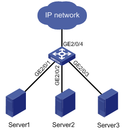
As shown in Figure 1-1, the network card transmission rate of the server group (Server 1, Server 2, and Server 3) is 1000 Mbps, and the transmission rate of GigabitEthernet 2/0/4, which provides access to the external network for the server group, is 1000 Mbps too. If you do not specify an auto-negotiation transmission rate, the transmission rate on GigabitEthernet 2/0/1, GigabitEthernet 2/0/2 and GigabitEthernet 2/0/3 through negotiation with the servers is 1000 Mbps, which may cause congestion on the egress interface GigabitEthernet2/0/4. To solve the problem, you can specify the auto-negotiation transmission rate on GigabitEthernet 2/0/1, GigabitEthernet 2/0/2, and GigabitEthernet 2/0/3 to 100 Mbps.
Follow these steps to configure an auto-negotiation transmission rate:
|
To do… |
Use the command… |
Remarks |
|
Enter system view |
system-view |
— |
|
Enter Ethernet interface view |
interface interface-type interface-number |
— |
|
Configure the auto-negotiation transmission rate range |
speed auto [ 10 | 100 | 1000 ] * |
Optional By default, the port speed is in the auto-negotiation mode. |
![]()
l This function is available for auto-negotiation-capable 100 MB or Gigabit Layer-2 Ethernet interfaces only. For a Combo port, only the electrical port supports this function.
l If you repeatedly use the speed and the speed auto commands to configure the transmission rate on an interface, only the latest configuration takes effect.
Configuring Storm Suppression
You can use the following commands to suppress the broadcast, multicast, and unknown unicast traffic. In interface configuration mode, the suppression ratio indicates the maximum broadcast, multicast or unknown unicast traffic that is allowed to pass through an interface. When the broadcast, multicast, or unknown unicast traffic over the interface exceeds the threshold, the system will discard the extra packets so that the broadcast, multicast or unknown unicast traffic ratio can drop below the limit to ensure that the network functions properly.
![]()
l The storm suppression ratio settings configured for an Ethernet interface may get invalid if you enable the storm constrain for the interface. For information about the storm constrain function, see Configuring the Storm Constrain Function on an Ethernet Interface.
l On an Ethernet port enabled with storm suppression ratio, this feature takes effect only in the inbound direction.
Follow these steps to set storm suppression ratios for one or multiple Ethernet interfaces:
|
To do… |
Use the command… |
Remarks |
|
|
Enter system view |
system-view |
— |
|
|
Enter Ethernet interface view or port group view |
Enter Ethernet interface view |
interface interface-type interface-number |
Use either command. If configured in Ethernet interface view, this feature takes effect on the current port only; if configured in port group view, this feature takes effect on all ports in the port group. |
|
Enter port group view |
port-group manual port-group-name |
||
|
Set the broadcast storm suppression ratio |
broadcast-suppression { ratio | pps max-pps } |
Optional By default, all broadcast traffic is allowed to pass through an interface, that is, broadcast traffic is not suppressed. |
|
|
Set the multicast storm suppression ratio |
multicast-suppression { ratio | pps max-pps } |
Optional By default, all multicast traffic is allowed to pass through an interface, that is, multicast traffic is not suppressed. |
|
|
Set the unknown unicast storm suppression ratio |
unicast-suppression { ratio | pps max-pps } |
Optional By default, all unknown unicast traffic is allowed to pass through an interface, that is, unknown unicast traffic is not suppressed. |
|
![]()
If you set storm suppression ratios in Ethernet interface view or port group view repeatedly for an Ethernet interface that belongs to a port group, only the latest settings take effect.
Setting the Interval for Collecting Ethernet Interface Statistics
Follow these steps to configure the interval for collecting interface statistics:
|
To do… |
Use the command… |
Remarks |
|
Enter system view |
system-view |
— |
|
Configure the interval for collecting interface statistics |
interface interface-type interface-number |
Optional The default interval for collecting interface statistics is 300 seconds. |
|
flow-interval interval |
Enabling Forwarding of Jumbo Frames
Due to tremendous amount of traffic occurring on an Ethernet interface, it is likely that some frames greater than the standard Ethernet frame size are received. Such frames (called jumbo frames) will be dropped. With forwarding of jumbo frames enabled, upon receiving jumbo frames with a size greater than the standard Ethernet frame size and yet within the specified parameter range, the system will process such frames sequentially.
l If you execute the command in Ethernet interface view, the configurations take effect only on the current interface.
l If you execute the command in port-group view, the configurations take effect on all ports in the port group.
Follow these steps to enable the forwarding of jumbo frames:
|
To do… |
Use the command… |
Remarks |
|
|
Enter system view |
system-view |
— |
|
|
Enable the forwarding of jumbo frames |
In port-group view |
port-group manual port-group-name |
Use any command. By default, the device allows jumbo frames with the length of 1,536 bytes to pass through all Layer 2 Ethernet interfaces. |
|
jumboframe enable [ value ] |
|||
|
In Ethernet interface view |
interface interface-type interface-number |
||
|
jumboframe enable [ value ] |
|||
![]()
If you set the value argument for ports of a port group in Ethernet interface view or port-group view for multiple times, the latest configuration takes effect.
Enabling Loopback Detection on an Ethernet Interface
If a port receives a packet that it sent out, a loop occurs. Loops may cause broadcast storms. The purpose of loopback detection is to detect loops on an interface.
When loopback detection is enabled on an Ethernet interface, the device periodically checks whether the ports have any external loopback. If it detects a loopback on a port, the device will set that port to be under loopback detection mode.
l If loops are detected on an access port, the port will transit to the loopback detection control state, where the incoming packets of the port are dropped and the outgoing packets of the port are forwarded normally. Meanwhile, trap messages will be sent to the terminal, and the corresponding MAC address forwarding entries will be removed.
l If loops are detected on a trunk port or a hybrid port, trap messages are sent to the terminal. If the loopback detection control function is also enabled on the port, the port will transit to the loopback detection control state, where the incoming packets of the port are dropped and the outgoing packets of the port are forwarded normally, trap messages will be sent to the terminal, and the corresponding MAC address forwarding entries will be removed.
Follow these steps to configure loopback detection:
|
To do… |
Use the command… |
Remarks |
|
Enter system view |
system-view |
— |
|
Enable global loopback detection |
loopback-detection enable |
Required Disabled by default |
|
Configure the interval for port loopback detection |
loopback-detection interval-time time |
Optional 30 seconds by default |
|
Enter Ethernet interface view |
interface interface-type interface-number |
— |
|
Enable loopback detection on a port |
loopback-detection enable |
Required Disabled by default |
|
Enable loopback detection control on a trunk port or a hybrid port |
loopback-detection control enable |
Optional Disabled by default |
|
Enable loopback detection in all the VLANs to which trunk or hybrid ports belong |
loopback-detection per-vlan enable |
Optional Enabled only in the default VLAN(s) with trunk port or hybrid ports |
![]()
l Loopback detection on a given port is enabled only after the loopback-detection enable command has been configured in both system view and the interface view of the port.
l Loopback detection on all ports will be disabled after the configuration of the undo loopback-detection enable command under system view.
l Member ports in aggregation groups do not support loopback detection.
Configuring the MDI Mode for an Ethernet Interface
![]()
Combo ports operating as optical ports do not support this feature.
Two types of Ethernet cables can be used to connect Ethernet devices: crossover cable and straight-through cable. To accommodate these two types of cables, an Ethernet interface on a device can operate in one of the following three Medium Dependent Interface (MDI) modes:
l Across mode
l Normal mode
l Auto mode
An Ethernet interface is composed of eight pins. By default, each pin has its particular role. For example, pin 1 and pin 2 are used for transmitting signals; pin 3 and pin 6 are used for receiving signals. You can change the pin roles through setting the MDI mode. For an Ethernet interface in normal mode, the pin roles are not changed. For an Ethernet interface in across mode, pin 1 and pin 2 are used for receiving signals; pin 3 and pin 6 are used for transmitting signals. To enable normal communication, you should connect the local transmit pins to the remote receive pins. Therefore, you should configure the MDI mode depending on the cable types.
l Normally, the auto mode is recommended. The other two modes are useful only when the device cannot determine the cable type.
l When straight-through cables are used, the local MDI mode must be different from the remote MDI mode.
l When crossover cables are used, the local MDI mode must be the same as the remote MDI mode, or the MDI mode of at least one end must be set to auto.
Follow these steps to configure the MDI mode for an Ethernet interface:
|
To do… |
Use the command… |
Remarks |
|
Enter system view |
system-view |
— |
|
Enter Ethernet interface view |
interface interface-type interface-number |
— |
|
Configure the MDI mode for the Ethernet interface |
mdi { across | auto | normal } |
Optional Defaults to auto. That is, the Ethernet interface determines the physical pin roles (transmit or receive) through negotiation. |
Testing the Cable on an Ethernet Interface
![]()
l The optical interface of a Combo port does not support this feature. The support of other Ethernet interfaces for this feature depends on the device model.
l A link in the up state goes down and then up automatically if you perform the operation described in this section on one of the Ethernet interfaces forming the link.
Follow these steps to test the current operating state of the cable connected to an Ethernet interface:
|
To do… |
Use the command… |
Remarks |
|
Enter system view |
system-view |
— |
|
Enter Ethernet interface view |
interface interface-type interface-number |
— |
|
Test the cable connected to the Ethernet interface once |
virtual-cable-test |
Required |
Configuring the Storm Constrain Function on an Ethernet Interface
The storm constrain function suppresses packet storms in an Ethernet. With this function enabled on an interface, the system detects the multicast traffic or broadcast traffic passing through the interface periodically and takes corresponding actions (that is, blocking or shutting down the interface and sending trap messages and logs) when the traffic detected exceeds the threshold.
![]()
Alternatively, you can configure the storm suppression function to control a specific type of traffic. As the function and the storm constrain function are mutually exclusive, do not enable them at the same time on an Ethernet interface. For example, with broadcast storm suppression ratio set on an Ethernet interface, do not enable the storm constrain function for broadcast traffic on the interface. Refer to Configuring Storm Suppression for information about the storm suppression function.
With the storm constrain function enabled on an Ethernet interface, you can specify the system to act as follows when the traffic detected exceeds the threshold.
l Blocking the interface. In this case, the interface is blocked and thus stops forwarding the traffic of this type till the traffic detected is lower than the threshold. Note that an interface blocked by the storm constrain function can still forward other types of traffic and monitor the blocked traffic.
l Shutting down the interface. In this case, the interface is shut down and stops forwarding all types of traffic. Interfaces shut down by the storm constrain function can only be brought up by using the undo shutdown command or disabling the storm constrain function.
Follow these steps to configure the storm constrain function on an Ethernet interface:
|
To do… |
Use the command… |
Remarks |
|
Enter system view |
system-view |
— |
|
Set the interval for generating traffic statistics |
storm-constrain interval seconds |
Optional 10 seconds by default |
|
Enter Ethernet interface view |
interface interface-type interface-number |
— |
|
Enable the storm constrain function and set the lower threshold and the upper threshold |
storm-constrain { broadcast | multicast } pps max-pps-values min-pps-values |
Required Disabled by default |
|
Set the action to be taken when the traffic exceeds the upper threshold |
storm-constrain control { block | shutdown } |
Optional Disabled by default |
|
Specify to send trap messages when the traffic detected exceeds the upper threshold or drops down below the lower threshold from a point higher than the upper threshold |
storm-constrain enable trap |
Optional By default, the system sends trap messages when the traffic detected exceeds the upper threshold or drops down below the lower threshold from a point higher than the upper threshold. |
|
Specify to send log when the traffic detected exceeds the upper threshold or drops down below the lower threshold from a point higher than the upper threshold |
storm-constrain enable log |
Optional By default, the system sends log when the traffic detected exceeds the upper threshold or drops down below the lower threshold from a point higher than the upper threshold. |
![]()
l For network stability sake, configure the interval for generating traffic statistics to a value that is not shorter than the default.
l The storm constrain function, after being enabled, requires a complete statistical period (specified by the storm-constrain interval command) to collect traffic data, and analyzes the data in the next period. Thus, it is normal that a period longer than one statistic period is waited for a control action to happen if you enable the function while the packet storm is present. However, the action will be taken within two periods.
l The storm constrain function is applicable to multicast packets and broadcast packets; and you can specify the upper and lower threshold for any of the three types of packets.
Displaying and Maintaining an Ethernet Interface
|
To do… |
Use the command… |
Remarks |
|
Display the current state of an interface and the related information |
display interface [ interface-type [ interface-number ] ] |
Available in any view |
|
Display the summary of a interface |
display brief interface [ interface-type [ interface-number ] ] [ | { begin | exclude | include } regular-expression ] |
Available in any view |
|
Clear the statistics of a interface |
reset counters interface [ interface-type [ interface-number ] ] |
Available in user view |
|
Display the Combo ports and the corresponding optical/electrical ports |
display port combo |
Available in any view |
|
Display the information about a manual port group or all the port groups |
display port-group manual [ all | name port-group-name ] |
Available in any view |
|
Display the information about the loopback function |
display loopback-detection |
Available in any view |
|
Display the information about storm constrain |
display storm-constrain [ broadcast | multicast ] [ interface interface-type interface-number ] |
Available in any view |
