- Table of Contents
-
- 01-Access Volume
- 00-Access Volume Organization
- 01-Ethernet Interface Configuration
- 02-Link Aggregation Configuration
- 03-Port Isolation Configuration
- 04-Service Loopback Group Configuration
- 05-DLDP Configuration
- 06-Smart Link Configuration
- 07-LLDP Configuration
- 08-VLAN Configuration
- 09-GVRP Configuration
- 10-QinQ Configuration
- 11-BPDU Tunneling Configuration
- 12-VLAN Mapping Configuration
- 13-Ethernet OAM Configuration
- 14-Connectivity Fault Detection Configuration
- 15-EPON-OLT Configuration
- 16-MSTP Configuration
- 17-RRPP Configuration
- 18-Mirroring Configuration
- Related Documents
-
| Title | Size | Download |
|---|---|---|
| 15-EPON-OLT Configuration | 605.13 KB |
Table of Contents
Benefits of the EPON Technology
Data Transmission in an EPON System
Extended OAM Connection Establishment
S7500E Series Switches and EPON System
Features of an S7500E Switch Working as an OLT Device
Three Port Types in an EPON System
S7500E OLT Configuration Task List
EPON System Parameter Configuration
Configuring Dynamic Bandwidth Allocation and Related Parameters
Configuring Grant filtering on the OLT port
Configuring the Link Type of an OLT Port
Displaying and Maintaining OLT Configuration
OLT Port Isolation Configuration Example
Fiber Backup Configuration Example
3 ONU Remote Management Configuration
Binding an ONU with an ONU Port
Configuring the Management VLAN of the ONU
Enabling Related Protocols on an ONU
Configuring the Multicast Mode of the ONU
Configuring the Link Type of an ONU Port
Configuring an ONU to Report Information to the OLT
Configuring Traffic Encryption
Testing the Link Between an ONU and the OLT
Displaying and Maintaining ONU Port Configuration
Configuration Examples for ONU Remote Management
Configuration Example for Binding an ONU Port to an ONU
ONU RSTP Configuration Example
Multicast Configuration Example (in IGMP Snooping Mode)
Multicast Configuration Example (in Multicast Control Mode)
ONU Update Configuration Example
UNI Port Configuration Task List
Configuring the VLAN Operation Mode for a UNI
Configuring Fast-Leave Processing for a UNI
Configuring Port Isolation for a UNI
Displaying and Maintaining UNI Port Configuration
Configuring Alarms on an OLT Port
Configuring Alarms on an ONU Port
Displaying and Maintaining Alarm Configurations
6 Supported Switch Features and Restrictions
OLT Port Features and Restrictions
ONU Port Features and Restrictions
Introduction to EPON System
Ethernet Passive Optical Network (EPON) is a Passive Optical Network (PON) which carries Ethernet frames encapsulated in 802.3 standards. It is a combination of the Ethernet technology and the PON technology in compliance with the IEEE 802.3ah standards issued in June, 2004.
EPON Architecture
A typical EPON system consists of three components: optical line terminal (OLT), optical network unit (ONU), and optical distribution network (ODN), as shown in Figure 1-1.
Figure 1-1 A typical EPON architecture
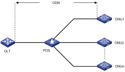
OLT
An OLT, generally an Ethernet switch, router, or multimedia conversion platform, is located at the central office (CO) as a core device of the whole EPON system to provide core data and video-to-telephone network interfaces for EPON and the service provider.
ONU
ONUs are used to connect the customer premise equipment, such as PCs, set-top boxes (STBs), and switches. Generally placed at customer's home, corridors, or roadsides, ONUs are mainly responsible for forwarding uplink data sent by customer premise equipment (from ONU to OLT) and selectively receiving downlink broadcasts forwarded by OLTs (from OLT to ONU).
ODN
An ODN consists of optical fibers, one or more passive optical splitters (POSs), and other passive optical components. ODNs provide optical signal transmission paths between OLTs and ONUs.
A POS can couple uplink data into a single piece of fiber and distribute downlink data to respective ONUs.
Benefits of the EPON Technology
Lower operation and maintenance costs
Compared with a traditional Ethernet broadband access network, an EPON network greatly lowers the operation and maintenance costs. This is because, as passive equipment in an EPON system, POSs are energy-saving (requiring no power supply), highly reliable (not affected in case of a power outage), and easy to install, and save optical fiber resources.
Long distances and higher bandwidths
Compared with an Ethernet broadband access network, an EPON system provides a longer access transmission distance (up to 20 km, or 12.43 miles) and higher bandwidth (1 Gbps) that can adapt to the service status of the ONUs in real time. Each ONU enjoys dedicated line quality similar to Time Division Multiplexing (TDM) with dedicated uplink bandwidth in the grant cycle assigned to it.
EPON Application Mode
Based on where ONUs are deployed, EPON application mode can be Fiber To The Curb (FFTC), Fiber To The Building (FTTB), and Fiber To The Home (FTTH).
FTTC
In an FTTC system, ONUs are deployed at roadside or beside the junction boxes of telegraph poles. Usually, twisted-pair copper wires are used to connect the ONUs to each user, and coaxial cables are used to transmit broadband graphic services. One of the main benefits of the FTTC technology is that it allows the existing copper wire infrastructure to continue to be used between the ONUs and customer premises, thus postponing the investments on optical fibers to the home. Currently, the FTTC technology is the most practical and economical Optical Access Network (OAN) solution for providing narrowband services below 2 Mbps. For services integrating narrowband and broadband services, however, FTTC is not the ideal solution.
FTTB
In an FTTB system, ONUs are deployed within buildings, with the optical fibers led into user homes through ADSL lines, cables, or LANs. Compared with FTTC, FTTB has a higher usage of optical fiber and therefore is more suitable for user communities that are dense or need narrowband/broadband integrated services.
FTTH
In an FTTH system, ONUs are deployed in user offices or homes to implement a fully transparent optical network, with the ONUs independent of the transmission mode, bandwidth, wavelength, and transmission technology. Therefore, FTTH is ideal for the long term development of optical access networks.
Data Transmission in an EPON System
An EPON system uses the single-fiber wavelength division multiplexing (WDM) technology (with downlink central wavelength of 1490 nm and uplink central wavelength of 1310 nm) to implement single-fiber bidirectional transmission, supporting a transmission distance of up to 20 km (12.43 miles).
As shown in Figure 1-2, before an EPON system transmits data, ONU registration (See ONU Registration), extended OAM connection establishment (See Extended OAM Connection Establishment), and bandwidth allocation (See Bandwidth Allocation) are required.
Figure 1-2 Data transmission in an EPON system
![]()
ONU Registration
Four types of Multipoint Control Protocol (MPCP) messages are used in ONU registration: GATE, REGISTER_REQ, REGISTER, and REGISTER_ACK. Each of these messages contains a time stamp field that records the local clock at the time of packet transmission. There are two types of GATE messages:
l General GATE messages, which allocate bandwidths in unicast mode.
l Discovery GATE messages, which discover ONUs in broadcast mode.
An ONU registration process is as follows:
1) An OLT broadcasts a discovery GATE message to notify the start time and length of the discovery timeslot to all the ONUs.
2) An unregistered ONU responds to the discovery GATE message and modifies its local clock to be consistent with the time stamp contained in the GATE message. When the local clock of the ONU reaches the start time of the discovery timeslot, the ONU waits a random period of delay before sending a REGISTER_REQ message, which contains the MAC address of the ONU and the local time stamp of the ONU when the REGISTER_REQ message is sent.
3) Upon receiving the REGISTER_REQ message from the unregistered ONU, the OLT obtains the ONU's MAC address and ONU-OLT round trip time (RTT) (For the RTT measurement, see Configuring the maximum ONU-OLT RTT. The ONU-OLT RTT is mainly used for the time synchronization between an OLT and ONUs.
4) The OLT parses the received REGISTER_REQ message, and uses the MAC address contained in the message to unicast a REGISTER message to the unregistered ONU. The REGISTER message contains a Logical Link ID (LLID) assigned to the ONU as the unique identifier of the ONU.
5) Right after sending a REGISTER message, the OLT sends a general GATE message to the same ONU.
6) After receiving the REGISTER message and general GATE message, the ONU sends a REGISTER_ACK message in the timeslot assigned in the GATE message to notify the OLT that the REGISTER message is parsed successfully.
7) The ONU registration is complete.
Extended OAM Connection Establishment
The EPON cards of the S7500E series Ethernet switches support the Operation, Administration and Maintenance (OAM) functions and extended OAM functions. This enables OLTs to remotely operate, manage, and maintain ONUs.
Extended OAM connection establishment includes OAM capability discovery and exchange of additional information. It is the capability acknowledgement process required before completing other extended OAM functions. Data transmission begins only after the extended OAM connection is established. The process of extended OAM connection establishment is as follows:
1) Standard OAM discovery establishment is complete.
2) The ONU reports the supported Organizationally Unique Identifier (OUI) and extended OAM version number to the OLT.
3) The OLT checks whether the reported OUI and extended OAM version number are in the list of OUIs and extended OAM version numbers supported by the OLT:
l If yes, the extended OAM connection for the ONU is established successfully;
l Otherwise, the extended OAM connection for the ONU cannot be established.
![]()
For detailed OAM and extended OAM descriptions, refer to the "Ethernet OAM" module of this manual.
Bandwidth Allocation
Once the extended OAM connection is established, downlink data transmission can begin. Uplink data transmission can begin only after uplink bandwidth is allocated.
In bandwidth allocation, mainly two types of MPCP messages: GATE and REPORT, are used:
l A GATE message is sent by an OLT to assign a transmission timeslot to an ONU.
l A REPORT message is sent by an ONU to feed back the local status information, such as buffer occupancy, to the OLT, helping the OLT assign timeslots intelligently.
An OLT allocates bandwidth to an ONU as follows:
1) The OLT sends a GATE message to notify the ONU of the timeslot for sending a REPORT message.
2) The ONU sends a REPORT message within the assigned timeslot to report its local status information to the OLT.
3) Upon receiving the REPORT message from the ONU, the OLT, based on the current bandwidth of the system, assigns the ONU a data transmission timeslot, which contains the start time and length for transmitting data by the ONU.
4) The ONU receives the GATE message and waits for the arrival of the start time contained in the GATE message. Once the start time is reached, data transmission begins.
5) The bandwidth allocation is complete.
Data Transmission
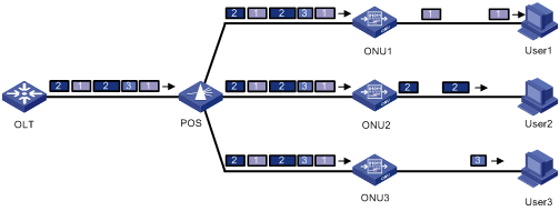
Downlink data transmission
Downlink data is broadcast to the ONUs, with each ONU receiving only the packets destined to it and discarding other packets, as shown in Figure 1-3.
Figure 1-3 Downlink data transmission in an EPON system
Uplink data transmission
As shown in Figure 1-4, each ONU buffers the data frames received from users and sends the buffered data frames at the full wire-speed (1000 Mbps) once the timeslot for the ONU arrives.
Figure 1-4 Uplink data transmission in an EPON system
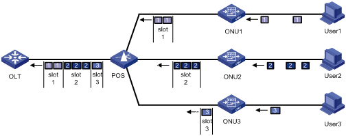
The Time Division Multiple Access (TDMA) technology is used to transmit uplink data. This ensures that one optical fiber between the OLT and the POS can transmit data signals from multiple ONUs to the OLT without signal interference.
EPON System Security
Downlink data through the OLT is broadcast to each ONU. To prevent illegal interception of user information, each LLID in an EPON system is assigned a unique key, which is updated periodically:
In a key update process, the OLT sends a new key request message to an ONU. Upon receiving the new key request message, the ONU sends a new key notification message back to the OLT.
In a key update process, an OLT uses the key update timer and encryption response timer:
1) OLT key update timer
This timer is used to control the key update cycle. When the key update timer expires, the OLT sends another key request message to start another key update process.
2) OLT encryption response timer
This timer is used to start another key update process when the OLT receives no new key notification message, thus making the key update more reliable.
Upon sending a key update request message, the OLT starts the encryption response timer:
l If the OLT receives a correct new key notification message from an ONU before the timer expires, the OLT enables the new key and cancels the timer.
l If the OLT receives no new key notification message before the timer expires, the OLT considers the key update process has failed, resets the timer, and sends another key update request message. Before the key update succeeds, an ONU keeps using the original key and the OLT reports the key update failure information to the network management system.
l If the OLT receives no new key notification message within the encryption response timer duration after sending three new key request messages consecutively, the OLT sends an alarm to the network management system and the old key continues to be used for downlink data. In this case, you are recommended to adjust the value of the encryption response timer.
EPON System Reliability
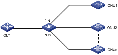
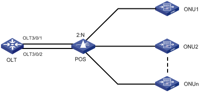
To ensure high reliability for the trunk fibers and OLTs in an EPON system, you can add two OLT ports on one EPON card or on two different EPON cards to a fiber backup group. When a system fault occurs, for example, when a trunk fiber is broken or an OLT port becomes abnormal, a switchover is performed automatically between the two OLTs, which act as backup for each other. You can also perform a manual switchover between two OLT ports added to the backup group as needed. Figure 1-5 depicts a fiber backup group, where POS is a 2:N optical splitter.
Figure 1-5 Network diagram for a fiber backup group
S7500E Series Switches and EPON System
Features of an S7500E Switch Working as an OLT Device
With an EPON card installed, an S7500E switch can work as an OLT device in an EPON system. In such a case, the S7500E switch has the following features:
l Compliance with EPON interoperation standards: Interoperable with other vendors' ONUs that support China Telecom Technical Requirements for EPON Devices.
l Integrating access and convergence: Each EPON card in an S7500E switch has multiple physical OLT ports, and each OLT port has 64 logical ports, namely, ONU ports, each of which can correspond with an ONU. Thus, one EPON card can work as multiple OLT devices. This reduces users' equipment purchase costs, and the management costs and fault ratio caused by interconnection between multiple device ports.
l Powerful ONU remote management capabilities: You can centrally manage and configure different services on ONUs and ONU UNI (User Network Interface) ports through OLTs. This greatly lowers subsequent maintenance costs.
l Excellent security protection: OLTs can protect network devices in terms of control, management, and forwarding against illegal access or abnormal traffic.
l Powerful access control list (ACL) and QoS functions: OLTs support standard and extended ACLs, and support traffic policing, traffic shaping, packet priority, multiple queue scheduling mechanisms, multiple congestion avoidance mechanisms, and other QoS assurance functions.
Three Port Types in an EPON System
When an S7500E switch works as an OLT device in an EPON system, the EPON system has three port types: OLT, ONU, and UNI, as shown in Figure 1-6.
OLT port
Each PON port on an EPON card in an S7500E switch is an independent OLT device. For an S7500E switch, a PON port is an OLT port. An OLT port number is in the format EPON card slot number/sub-card slot number/OLT port number, such as OLT 3/0/1, as shown in Figure 1-6.
ONU port
Each OLT port of an S7500E switch has 64 logical ONU ports. An ONU port becomes a physical port only after an ONU device is bound with it. The configurations performed in ONU port view take effect on the corresponding ONU device. An ONU port number is in the format EPON card slot number/sub-card slot number/OLT port number: ONU port number, such as ONU 3/0/1:1, as shown in Figure 1-6.
UNI Port
A UNI port is an ONU device port connected to a user. The UNI port number supported by an S7500E switch is in the range 1 to 80. The actual numbers vary with ONU devices. For example, when the ONU device corresponding to ONU 3/0/1:1 in an EPON system is S3100-16C-EPON-EI, the UNI port number is in the range 1 to 16.
S7500E OLT Configuration Task List
Figure 1-6 shows an EPON system networking diagram, which assumes that only two ONUs are attached to one OLT port and each ONU is connected to only one user.
Based on the three port types (OLT, ONU, and UNI) shown in Figure 1-6, this document details the functions of an S7500E Ethernet switch working as an OLT device and the configurations for the functions.
Complete the following tasks to configure OLT on an S7500E switch:
|
Task |
Remarks |
|
l EPON system parameter description and configuration l Description and configuration of the functions of an S7500E switch working as an OLT device |
|
|
Description and configuration procedure of ONU remote management through OLT |
|
|
l UNI port introduction l Configuration procedure of UNI remote management through OLT |
|
|
Configurations of all the alarms in an EPON system |
|
|
Switch features supported by OLTs and ONUs, related manuals, and cautions |
![]()
l When working as an OLT device, an S7500E switch supports abundant features. This chapter describes only the functions of an S7500E switch working as an OLT device. For other functions, see OLT Port Features and Restrictions.
l If the OLT configurations in this manual take effect only when the OLT is used together with ONUs manufactured by H3C (hereinafter referred to as H3C ONUs), related descriptions will be given in the configuration task list in each chapter; if no such description is given, the OLT configurations will take effect on all the ONUs compliant with China's EPON standards.
OLT Configuration
OLT Configuration Task List
Complete the following tasks to configure an OLT:
|
Task |
Remarks |
|
|
Configuring OUI and extended OAM version number list |
Optional |
|
|
Configuring the maximum ONU-OLT RTT |
Optional |
|
|
Configuring the timeout time of the extended OAM messages |
Optional |
|
|
Configuring the key update time and encryption reply timeout time of the encryption |
Optional |
|
|
Configuring Dynamic Bandwidth Allocation and Related Parameters |
Optional |
|
|
Optional |
||
|
Optional |
||
|
Optional |
||
|
Optional |
||
EPON System Parameter Configuration
Configuring the maximum ONU-OLT RTT
During ONU registration, an OLT obtains the Round Trip Time (RTT) value of an ONU through the exchange of discovery GATE messages and REGISTER_REQ messages between the OLT and the ONU. By configuring a maximum RTT at the OLT side, you can set the coverage range of the EPON system. An ONU whose RTT is greater than the RTT configured on the OLT cannot be registered.
Setting a short RTT prevents ONUs too far away from the OLT from being registered with the EPON system (a far-away ONU suffers high optical power attenuation). Setting a long RTT can expand the coverage range of the EPON system, allowing as many ONUs as possible to be registered successfully.
The process of RTT measurement is as follows:
1) The OLT sends an ONU a discovery GATE message containing the OLT local time T0, namely, the time stamp in the discovery GATE message is T0.
2) Upon receiving the discovery GATE message, the ONU modifies its local time to be the time stamp T0 in the message and sends a REGISTER_REQ message to the OLT at T1 after a delay (the time stamp of the REGISTER_REQ message is T1).
3) The OLT receives the REGISTER_REQ message at T2.
4) The OLT calculates the ONU RTT by using the formula: RTT=(T2-T0)-(T1-T0)=T2-T1.
5) If the OLT becomes idle at T3 and remains idle for a period of ∆T, the timeslot assigned to the ONU is { T3-RTT, ∆T }. That is, the ONU will start sending data at T3-RTT and send data for a period of ∆T.
Follow these steps to configure EPON system parameters:
|
To do… |
Use the command… |
Remarks |
|
Enter system view |
system-view |
— |
|
Enter OLT port view |
interface olt interface-number |
— |
|
Configure the Maximum ONU-OLT RTT |
max-rtt value |
Optional 13524 TQ by default |
|
Exit to system view |
quit |
— |
|
Enter FTTH view |
ftth |
— |
|
Configure OUI and extended OAM version number list |
epon-parameter ouilist { oui oui-value oam-version version-value } &<1-9> slot slot-number |
Required By default, the OUI and extended OAM version number must be configured as 111111 and 1 respectively. |
|
Configure the key update time and encryption reply timeout time of the encryption |
encryption timer { update update-time | no-reply-timeout timeout }* slot slot-number |
Optional By default, the key update time is 10 seconds and the encryption reply timeout time is 3000 milliseconds. |
![]()
l When the OUI and OAM version number list on an EPON service board changes due to addition or removal of user-defined list entry, all ONUs under the board will re-register.
l It is recommended that you configure the maximum ONU-OLT RTT only when necessary. The relationship between the RTT and the distance (in meters) from the OLT to the ONU can be roughly expressed by the formula: RTT = (Distance + 157)/1.6393.
l The max-rtt command is applicable to unregistered ONUs only.
l The encryption reply timeout time must be less than or equal to the key update time.
Configuring Dynamic Bandwidth Allocation and Related Parameters
Dynamic bandwidth allocation (DBA) is used by an OLT to adjust the uplink bandwidth of individual ONUs in real time according to the traffic status of the ONUs.
BA is implemented through a request-response mechanism:
An OLT obtains the traffic information of ONUs from the bandwidth requests (REPORT messages) received from ONUs, uses a suitable bandwidth allocation algorithm to calculate the bandwidth to be allocated for this cycle within the specified uplink ONU bandwidth range, and notifies the results to the ONUs through bandwidth authorization (GATE messages). This ensures that uplink data sent by ONUs will not conflict with each other.
Compared with static (fixed) bandwidth allocation, DBA is more suitable for bursty IP/Ethernet services. DBA reduces bandwidth wastes and allows for more efficient uplink bandwidth utilization. With DBA adopted, the order and the time for ONUs to send uplink frames are controlled by the OLT.
There are two types of DBA algorithms: internal DBA algorithm and external DBA algorithm.
l The internal DBA algorithm is implemented internally by a chip.
l The external DBA algorithm is implemented through loading an external DBA algorithm file.
Follow these steps to configure dynamic bandwidth allocation and related parameters
|
To do... |
Use the command... |
Remarks |
||||
|
Enter system view |
system-view |
— |
||||
|
Enter OLT port view |
interface olt interface-number |
— |
||||
|
Use an external DBA algorithm |
Load the specified external DBA algorithm file |
dba-algorithm update file-url |
Use either internal DBA algorithm or external DBA algorithm. By default, the internal DBA algorithm is used. |
|||
|
Use the specified external DBA algorithm |
dba-algorithm enable extdba |
|||||
|
Use the internal DBA algorithm |
dba-algorithm enable intdba |
|||||
|
Configure the related parameters of ONU discovery |
dba-parameters { discovery-frequency value | discovery-length value | cycle-length value } * |
Optional By default, the discovery-frequency value is 50, the discovery-length value is 41500 TQ, and the cycle-length value is 65535 TQ. |
||||
|
Return to system view |
quit |
— |
||||
|
Enter ONU port view |
interface onu interface-number |
— |
||||
|
Set the ONU's uplink bandwidth limits and the delay mode of packet forwarding. |
upstream-sla { minimum-bandwidth value1 | maximum-bandwidth value2 | delay { low | high } } * |
Required By default, the minimum bandwidth of an ONU is 2048 kbps, the maximum bandwidth is 23552 kbps, and low delay is adopted. |
||||
|
Configure the administration attributes of DBA negotiation |
Configure the number of queue sets supported by ONU Report frames |
dba-report queue-set-number queue-set-number |
Optional By default, ONU Report messages support two queue sets. The default thresholds of queue 4 and queue 5 are 65535, while the default thresholds of other queues are 0. |
|||
|
Configure the threshold for a queue |
dba-report queue-id queue-id { active | inactive } threshold threshold-value |
|||||
![]()
l 1 time quantum (TQ) is equal to 16 ns, which is the time it takes to transmit two bytes of data at 1 Gbps.
l You can manually load an external DBA algorithm file by using the dba-algorithm update command as needed.
l DBA-related configuration is only recommended for administrators. Improper DBA configuration may terminate all the services.
l H3C ONU Report frames support up to two queue sets.
l The sum of the minimum uplink bandwidths configured for all created ONU ports under an OLT port cannot exceeds 921600 kbps, namely, 900 Mbps.
Configuring Grant filtering on the OLT port
In an EPON system, uplink transmission adopts the TDMA technology. An OLT assigns each ONU a time slot and each ONU can only send data in its own time slot in sequence. Therefore, the OLT implements strict time synchronization. Within the specified time, the OLT can only receive the packets from the specified ONU. If the time synchronization of an ONU is inaccurate, however, the packets that the OLT receives within a specified time period may be from another ONU. In that case, if grant filtering is enabled on the OLT port, the OLT does not allow the received packets to pass through.
Follow these steps to configure other OLT functions:
|
To do... |
Use the command... |
Remarks |
|
Enter system view |
system-view |
— |
|
Enter OLT port view |
interface olt interface-number |
— |
|
Enable grant filtering on the OLT port |
grant-filtering enable |
Optional Enabled by default |
Configuring the Link Type of an OLT Port
You can configure an OLT port as a hybrid port, and assign it to the specified VLANs in tagged mode or untagged mode.
Follow these steps to configure the link type of an OLT port:
|
To do… |
Use the command… |
Remarks |
|
Enter system view |
system-view |
— |
|
Enter OLT port view |
interface olt interface-number |
— |
|
Configure the OLT port as a hybrid port |
port link-type hybrid |
Optional |
|
Assign the port to the specified VLANs in tagged mode or untagged mode |
port hybrid vlan vlan-id-list { tagged | untagged } |
Required By default, an OLT port belongs to only VLAN 1 and forwards packets of VLAN 1 tagged. |
|
Configure the default VLAN of the OLT port |
port hybrid pvid vlan vlan-id |
Optional VLAN 1 by default |
![]()
The VLAN(s) that you assign an OLT port to must already exist.
Configuring Fiber Backup
For fiber backup description, see EPON System Reliability.
Follow these steps to configure fiber backup
|
To do... |
Use the command... |
Remarks |
|
|
Enter system view |
system-view |
— |
|
|
Enter FTTH view |
ftth |
— |
|
|
Create a fiber backup group |
fiber-backup group group-number |
Required |
|
|
Add an OLT port to a fiber backup group |
In fiber backup group view |
group member interface-type interface-number |
Required Use either one of the two methods |
|
In OLT port view |
quit |
||
|
quit |
|||
|
interface interface-type interface-number |
|||
|
port fiber-backup group group-number |
|||
|
quit |
|||
|
ftth |
|||
|
fiber-backup group group-number |
|||
|
Perform a master/slave switchover between the two OLT ports in the fiber backup group |
port switch-over |
Optional |
|
![]()
l Up to two OLT ports can be added to one backup group. An OLT port can be added to only one backup group at a time. The port added to the backup group earlier will be the master port, while the other port will be the standby port.
l Only one of the two OLT ports in a fiber backup group can be in the forwarding state.
l After the second OLT port is added to a backup group, you need to manually synchronize the configurations of the first OLT port and all the ONUs under it to the second OLT port. This ensures normal service operation after a master/standby switchover.
Displaying and Maintaining OLT Configuration
|
To do... |
Use the command... |
Remarks |
|
Display related information of EPON parameters |
display epon-parameter slot slot-number |
Available in FTTH view only |
|
Display the information about all the ONUs under an OLT port, ONU port, or the EPON board in the specified slot |
display onuinfo { interface interface-type interface-number | slot slot-number } |
Available in any view |
|
Display the information about the legal ONU with the specified MAC address |
display onuinfo mac-address mac-address |
|
|
Display the information about all the silent ONUs connected to the specified OLT port or to the EPON card seated in the specified slot |
display onuinfo silent { interface interface-type interface-number | slot slot-number } |
|
|
Display the optical parameter information of an OLT port |
display optics-parameters interface interface-type interface-number |
|
|
Display port version information |
display epon-version interface interface-type interface-number |
|
|
Display port capability information |
display epon-capability interface interface-type interface-number |
|
|
Display the current work mode of a port |
display epon-workmode interface interface-type interface-number |
|
|
Display the statistics on a port |
display epon statistics interface interface-type interface-number |
|
|
Display the OAM information about an ONU |
display epon-oam interface interface-type interface-number |
|
|
Display the master/standby port information of a backup group |
display fiber-backup group { all | group-number } |
|
|
Display the registration and deregistration information of an ONU |
display onu-event interface interface-type interface-number |
|
|
Display all the configuration information |
display current-configuration |
|
|
Display the configuration information in the current view |
display this |
![]()
l To display the information about an ONU, make sure the ONU is online. You can use the display onuinfo command to check whether an ONU is online.
l Port statistics data includes average error rate of data bits and data frames transmitted between an OLT and the ONUs. For detailed information, refer to the command manual.
OLT Configuration Examples
OLT Port Isolation Configuration Example
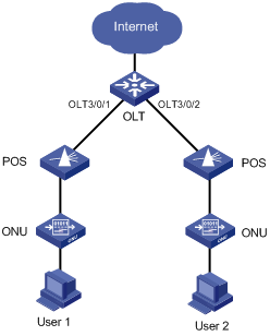
Network requirements
l An OLT device is connected to the Internet through the uplink port.
l Configure port isolation between OLT 3/0/1 and OLT 3/0/2 so that the users under OLT 3/0/1 and those under OLT 3/0/2 can access the Internet but cannot communicate with each other at Layer 2.
Network diagram
Figure 2-1 Network diagram for OLT port isolation
Configuration procedure
# Add OLT 3/0/1 and OLT 3/0/2 to an isolation group.
<Sysname> system-view
[Sysname] interface olt3/0/1
[Sysname-Olt3/0/1] port-isolate enable
[Sysname-Olt3/0/1] quit
[Sysname] interface olt3/0/2
[Sysname-Olt3/0/2] port-isolate enable
[Sysname-Olt3/0/2] quit
# Display the isolation group information.
<Sysname> display port-isolate group
Port-isolate group information:
Uplink port support: NO
Group ID: 1
olt3/0/1 olt3/0/2
Fiber Backup Configuration Example
Network requirements
l Add two OLT ports of the same EPON board to a fiber backup group one after the other.
l Perform a manual switchover between the two OLT ports. When the master port is shut down, the slave port becomes the new master port.
Network diagram
Figure 2-2 Network diagram for fiber backup group configuration
Configuration procedure
# Create fiber backup group 1.
<Sysname> system-view
[Sysname] ftth
[Sysname-ftth] fiber-backup group 1
Create group 1 successfully.
# Add port OLT 3/0/1 and then OLT 3/0/2 to fiber backup group 1. Thus, OLT 3/0/1 works as the master port and OLT 3/0/2 the slave port.
[Sysname-fiber-group1] group member olt3/0/1
[Sysname-fiber-group1] group member olt3/0/2
[Sysname-fiber-group1] display fiber-backup group 1
fiber backup group 1 information:
Member Role State
-----------------------------------------
Olt3/0/1 MASTER ACTIVE
Olt3/0/2 SLAVE READY
# Perform a master/slave switchover between OLT 3/0/1 and OLT 3/0/2.
[Sysname-fiber-group1] port switch-over
[Sysname-fiber-group1] display fiber-backup group 1
fiber backup group 1 information:
Member Role State
-----------------------------------------
Olt3/0/2 MASTER ACTIVE
Olt3/0/1 SLAVE READY
# Shut down OLT 3/0/2. You can see that OLT 3/0/1 becomes the new master port.
[Sysname-fiber-group1] quit
[Sysname] interface olt3/0/2
[Sysname-Olt3/0/2] shutdown
[Sysname-Olt3/0/2] display fiber-backup group 1
fiber backup group 1 information:
Member Role State
-----------------------------------------
Olt3/0/1 MASTER ACTIVE
Olt3/0/2 SLAVE DOWN
![]()
When an S7500E switch is working as an OLT device, you can configure a variety of functions on its ONU ports so that you can manage the connected ONUs remotely. This chapter describes only the functions and commands developed specially for ONU ports on such an S7500E switch. Other function configurations of ONU ports are basically the same as those of the Ethernet ports on an S7500E switch. For details, see ONU Port Features and Restrictions.
ONU Configuration
Currently, the H3C ONUs for the S7500E series switches fall into three types:
l ET704 series ONUs (For details, see H3C ET704 Series EPON ONUs User Manual.)
l S3100 series ONUs (For details, see H3C S3100 Series Ethernet Switches Quick Start.)
l EC series ONUs (For details, see H3C EC1001 Video Encoder User Manual.)
Support for OLT remote management commands varies with ONUs. For details, see the sections describing the supported configuration functions in ONU device user manuals. The following table lists the ONU remote management functions supported by an S7500E switch working as an OLT device.
ONU Configuration Task List
Complete the following tasks to configure an ONU:
|
Task |
Remarks |
|
|
Required |
||
|
Required |
||
|
Optional For H3C ONUs only |
||
|
Optional For H3C ONUs only |
||
|
Optional |
||
|
Optional |
||
|
Other ONU configurations |
Optional |
|
|
Optional |
||
|
Optional |
||
|
Optional |
||
|
ONU device management |
Optional |
|
|
Optional For H3C ONUs only |
||
|
Optional |
||
|
Optional |
||
Creating an ONU Port
You can manually create or delete an ONU port as needed.
Follow these steps to create an ONU port:
|
Use the command... |
Remarks |
|
|
Enter system view |
system-view |
— |
|
Enter OLT port view |
interface olt interface-number |
— |
|
Create ONU port(s) |
using onu { onu-number1 [ to onu-number2 ] } &<1-10> |
Required By default, no ONU port is created when an EPON card is started up. |
Binding an ONU with an ONU Port
An OLT supports ONU authentication based on ONU MAC address and denies illegal ONU access to the system. ONU authentication can be implemented by binding the ONU to an ONU port. During the ONU registration:
l The OLT broadcasts a discovery GATE message. After receiving the discovery GATE message, an unregistered ONU sends a REGISTER_REQ message, whose source MAC address is that of the ONU, at the time granted by the GATE message.
l Upon receiving the REGISTER_REQ message, the OLT checks whether the source MAC address contained in the message is bound with the ONU port of the local end. If yes, the ONU passes the authentication and the OLT replies with a REGISTER message; otherwise, the ONU cannot pass the authentication and therefore cannot be registered.
After passing the authentication, the ONU port goes up; that is, the ONU is online.
Before binding an ONU to an ONU port, make sure you have obtained the MAC address of the ONU.
Follow these steps to bind an ONU port to an ONU:
|
To do... |
Use the command... |
Remarks |
|
Enter system view |
system-view |
— |
|
Enter ONU port view |
interface onu interface-number |
— |
|
Bind the current ONU port to an ONU |
bind onuid onuid |
Required |
![]()
l An ONU port can only be bound with one ONU MAC address. Conversely, an ONU MAC address can only be bound to one ONU port under one OLT port.
l In fiber backup, an ONU can be bound with two ONU ports under two OLT ports acting as backups for each other.
Configuring the Management VLAN of the ONU
To manage an ONU through Telnet, make sure the ONU is assigned an IP address. Only the VLAN interface corresponding to the management VLAN can be assigned an IP address. You can designate the management VLAN through the command line.
The management VLAN interface of an ONU can obtain an IP address in one of the following two ways:
l Through manual configuration of IP addresses
l Through DHCP (with the ONU as a DHCP client)
Follow these steps to configure the management VLAN of the ONU
|
To do... |
Use the command... |
Remarks |
|
|
Enter system view |
system-view |
— |
|
|
Enter ONU port view |
interface onu interface-number |
— |
|
|
Configuring the management VLAN of the ONU |
management-vlan vlan-id |
Optional By default, the management VLAN of the ONU is VLAN 1. |
|
|
Bring up the management VLAN interface |
undo shutdown management-vlan-interface |
Required By default, a management VLAN interface is down. After the undo shutdown management-vlan-interface command is used: l A management VLAN interface is down if all the Ethernet ports in the management VLAN of the ONU are down. l A management VLAN interface is up if one or more Ethernet ports in the management VLAN of the ONU are up. |
|
|
Configure IP addresses |
Manual configuration |
ip address ip-address mask gateway gateway |
Either is required. Required, use either one of the two methods. By default, the management VLAN interface has no IP address. |
|
Automatic allocation |
ip address dhcp-alloc |
||
Enabling Related Protocols on an ONU
You can use an OLT to remotely enable RSTP, DHCP snooping, DHCP snooping Option82, and PPPoE+ on an ONU through extended OAM packets.
RSTP
Enabling RSTP on an ONU can eliminate the loops between the UNIs or in the user networks by blocking redundant links.
DHCP Snooping
After DHCP snooping is enabled on an ONU, a DHCP snooping table will be generated on the ONU to record the IP address and user MAC address information that the DHCP client obtains from the DHCP server, with each record being an entry in the DHCP snooping table.
DHCP Snooping Option82
With DHCP snooping Option82 enabled on an ONU,
l For DHCP request messages with Option82 fields, the ONU replaces the Option82 fields with the local one before broadcasting the DHCP request messages;
l For DHCP request messages without Option82 fields, the ONU adds the Option82 field (which contains ONU MAC addresses, number of the UNI connected to the DHCP client, and the VLAN to which the UNI belongs) into the request messages when the DHCP client connected to the ONU sends DHCP request messages to the DHCP server. This allows the DHCP client addresses to be recorded in the DHCP server.
PPPoE+
The Point-to-Point Protocol over Ethernet (PPPoE) technology interconnects large numbers of hosts through Ethernet, allowing the hosts to access the Internet through a far-end access device, and implementing control and accounting functions on each connected host. Operating in the client/server mode, PPPoE encapsulates PPP packets into Ethernet frames, and provides PPP connection over Ethernet.
PPPoE+, also known as PPPoE Intermediate Agent, is designed for broadband users using PPPoE mode authentication. PPPoE+ allows for user port identification by adding user port information into the PPPoE packets.
After PPPoE+ is enabled on an ONU, when a PPPoE client sends a request packet:
l If the request packet contains no PPPoE tag, the ONU adds the tag (containing the UNI port information) to the request packet and forwards the packet to the OLT side.
l If the request packet contains a PPPoE tag, the ONU directly forwards the request packet to the OLT side without adding any tag.
Follow these steps to enable related protocol(s) on an ONU:
|
To do... |
Use the command... |
Remarks |
|
Enter system view |
system-view |
— |
|
Enter ONU port view |
interface onu interface-number |
— |
|
Enable related protocol(s) on the ONU |
onu-protocol { stp | dhcp-snooping | dhcp-snooping information | pppoe } enable |
Optional By default: l RSTP is enabled on the ONU. l DHCP snooping, DHCP snooping Option82, and PPPoE+ are disabled on the ONU. |
![]()
l When STP is enabled globally on the S7500E switch, you should enable STP on all ONUs. Additionally, configure STP correctly to ensure that no ONU can be selected as the STP root bridge; otherwise, anomaly may occur on the network.
l STP runs normally only when all attached ONUs are H3C ONUs.
Configuring the Multicast Mode of the ONU
Prerequisites for multicast mode configuration
Through extended OAM, an OLT can be used to remotely configure the multicast mode of an ONU as either IGMP snooping mode or multicast control mode.
The configuration of a multicast IP address-to-multicast VLAN correspondence is used to add multicast address(es) to a multicast VLAN. Upon receiving an IGMP report message, the OLT determines whether the multicast IP address contained in the message belongs to the multicast VLAN. If yes, the OLT generates a multicast forwarding entry in the multicast VLAN of the multicast IP address; otherwise, the OLT directly discards the message. A multicast IP address can belong to only one multicast VLAN.
Follow these steps to complete the prerequisites for multicast mode configuration:
|
To do... |
Use the command... |
Remarks |
|
Enter system view |
system-view |
— |
|
Enter FTTH view |
ftth |
— |
|
Add multicast address(es) to a multicast VLAN |
multicast vlan-id vlan-id dest-ip ip-address-list |
Required |
|
Return to system view |
quit |
— |
|
Enable IGMP snooping globally |
igmp-snooping |
Required Disabled by default |
|
Return to system view |
quit |
— |
|
Enter VLAN view of a multicast VLAN |
vlan vlan-id |
— |
|
Enable IGMP snooping |
igmp-snooping enable |
Required Disabled by default |
|
Drop unknown multicast traffic |
igmp-snooping drop-unknown |
Optional |
Configuring the IGMP snooping mode
In the IGMP snooping mode, the OLT and ONUs mainly use IGMP report, leave, and query messages to manage dynamic multicast group membership. The OLT can implement simple user multicast access control through the multicast VLAN configuration on UNI ports of the ONU. More complex service access control is realized through the IPTV service platform.
l You can use the OLT to remotely configure the aging timer of the ONU router port, the aging timer of multicast group member ports, and the query response timer.
Table 3-1 Timers used by IGMP snooping
|
Timer name |
Time |
Messages received within timer expiry |
Action upon timer expiry |
|
Router port aging timer |
Aging time of a router port |
IGMP general query message, PIM message, Dvmrp Probe message |
Considers the port not a router port |
|
Aging timer for multicast group member port |
Aging time of the multicast group member port |
IGMP host report message |
Sends an IGMP group-specific query message to the multicast member port |
|
Query response timer |
Maximum response-to-query time |
IGMP report message |
Removes the port from the member port list of the multicast group |
l Configuring IGMP membership report suppression
When an ONU receives an IGMP membership report from a multicast group member, the ONU forwards the message to the OLT. Thus, when multiple members of a multicast group are attached to the ONU, the OLT will receive duplicate IGMP reports from these members.
With the IGMP report suppression function enabled, within each query cycle, the ONU forwards only the first IGMP report of a multicast group to the OLT and will not forward the subsequent IGMP reports from the same multicast group to the OLT. This helps to reduce the number of packets being transmitted over the network.
Follow these steps to configure multicast in IGMP snooping mode:
|
To do... |
Use the command... |
Remarks |
|
Enter system view |
system-view |
— |
|
Enter ONU port view |
interface onu interface-number |
— |
|
Configure the multicast mode of the ONU as IGMP snooping |
multicast-mode igmp-snooping |
Optional By default, the multicast mode of the ONU is IGMP Snooping. |
|
Add a UNI to the specified multicast VLAN(s) |
uni uni-number multicast vlan { vlan-id } & <1-50> |
Required |
|
Configure the number of multicast channels on the specified UNI |
uni uni-number multicast-group-number number |
Optional By default, the users connected to a UNI can access 64 multicast channels at the same time. |
|
Remove the VLAN tag of the downlink multicast flow on the UNI port |
uni uni-number multicast-strip-tag enable |
Optional By default, a UNI does not remove the VLAN tag of the downlink multicast flow. |
|
Configure the aging timer of the router port |
onu-protocol igmp-snooping router-aging-time seconds |
Optional 105 seconds by default |
|
Configure the query-response timer |
onu-protocol igmp-snooping max-response-time seconds |
Optional By default, the maximum response time of group-specific queries is 1 second. |
|
Configure the aging timer of the multicast member port |
onu-protocol igmp-snooping host-aging-time seconds |
Optional 260 seconds by default |
|
Enable IGMP membership report suppression |
onu-protocol igmp-snooping report-aggregation enable |
Optional Disabled by default |
|
Enable IGMP leave suppression |
onu-protocol igmp-snooping leave-aggregation enable |
Optional Enabled by default |
![]()
The max-response-time keyword in the onu-protocol igmp-snooping command sets the maximum response time of the group-specific queries. If the device receives no response at the first timeout of the maximum response time, it re-sends group-specific queries. If the device still receives no response within the maximum response time, the multicast group on the corresponding ONU is deleted.
Multicast control mode
1) OLT-side functions
l The OLT side maintains a user multicast service access control table to centrally manage user multicast service access rights.
l The OLT identifies users through user LLIDs and the VLAN tags (consistent with UNI port numbers) carried in uplink IGMP report messages, and determines whether a user has the right to access the requested multicast service and, if yes, the related parameters.
l The OLT uses extended multicast control OAM packets to send the ONU the user's access right to the multicast channel, allowing the ONU to forward or shut off the multicast traffic for the user. The network management system at the OLT side centrally manages the multicast access control. The OLT governs, while an ONU executes, multicast right management. Meanwhile, the OLT supports the cooperation between IGMP proxy and upper-layer multicast routers to dynamically request and deliver multicast traffic.
2) ONU-side functions
l The ONU side maintains a table for multicast address filtering and multicast forwarding. It performs flow control only for the current multicast service on the ONU.
l The ONU adds VLAN tags (A UNI port number is used as the VLAN tag. For example, the packets received on UNI 1 are tagged with VLAN 1.) to the IGMP report messages without VLAN tags to identify users, and transparently sends the messages to the OLT. Then the ONU adds or deletes the group address filtering and multicast forwarding entries on the ONU based on the multicast control OAM packets (containing a series of multicast control entries) delivered by the OLT, and forwards or shuts off the multicast traffic accordingly.
Follow these steps to configure multicast in multicast control mode:
|
To do... |
Use the command... |
Remarks |
|
Enter system view |
system-view |
— |
|
Enter ONU port view |
interface onu interface-number |
— |
|
Configure the multicast mode of the ONU as the multicast control mode |
multicast-mode multicast-control |
Required By default, the multicast mode of the ONU is IGMP Snooping. |
|
Configure the aging timer of the multicast group members in the multicast control mode |
multicast-control host-aging-time host-aging-time |
Optional 260 seconds by default |
|
Configure the access to multicast channels on the specified UNI |
uni uni-number multicast-control multicast-address { multicast-address [ to multicast-address ] } &<1-10> [ source-ip ip-address [ to ip-address ] ] rule { deny | permit [ channel-limit channel-number ] | preview time-slice preview-time [ preview-interval interval-time | preview-times preview-times [ reset-interval reset-interval-time ] ]* } |
Required |
|
Remove the VLAN tag of the downlink multicast flow on the UNI port |
uni uni-number multicast-strip-tag enable |
Optional By default, a UNI does not remove the VLAN tag of the downlink multicast flow. |
Configuring the Link Type of an ONU Port
You can configure an ONU port as an access port or trunk port.
l When a PC is directly connected to the ONU port, you can configure the ONU port as an access port, which receives and transmits only untagged packets.
l When a home gateway or Layer-2 switch is connected to the ONU port, you can configure the ONU port as a trunk port.
Different from Ethernet ports describe in VLAN Operation, ONU ports process uplink/downlink packets as described in Table 3-2.
Table 3-2 The link type of an ONU port and how it processes packets
|
Port type |
Traffic direction |
Processing |
|
Access |
Uplink packets |
Allow only untagged packets to pass through and tag these packets with the default VLAN tag. |
|
Downlink packets |
Allow only packets with the default VLAN tag to pass through and remove the tag of these packets. |
|
|
Trunk |
Uplink packets |
l For untagged packets, tag them with the default VLAN tag and forward them. l For tagged packets, forward them directly without any processing |
|
Downlink packets |
Allow only tagged packets to pass through. |
For how to configure the link type of an ONU port, refer to Setting the link type of an ONU port to access and Setting the link type of an ONU port to trunk. Note that:
l The access ports described in Table 3-2 do not include ports in the default state, namely, the access ports in VLAN 1.
l The link type of the ONU ports under the same OLT port must be the same (access or trunk). Thus, when an ONU port under an OLT port is configured as an access port in a VLAN other than VLAN 1, you can only configure the other ONU ports under the same OLT port as access ports or leave them in the default state (that is, access ports in VLAN 1); when the ONU port is configured as a trunk port, you can configure the other ONU ports as trunk ports or leave them in the default state.
l The ONU ports in the default state only allow untagged packets to pass through in the uplink direction and tag these packets with VLAN 1 tag. In the downlink direction, they only allow the packets with the VLAN 1 tag to pass through. Such ONU ports remove the VLAN tag of the downlink packets if the other ONU ports under the same OLT are configured as access ports, and do not remove the tag of the downlink packets if the other ONU ports under the same OLT port are configured as trunk ports.
Setting the link type of an ONU port to access
Follow these steps to set the link type of an ONU port to access:
|
To do… |
Use the command… |
Remarks |
|
Enter system view |
system-view |
— |
|
Enter ONU port view |
interface onu interface-number |
— |
|
Set the link type of the ONU port to access |
port link-type access |
Optional By default, the link type of an ONU port is access. |
|
Assign the ONU port to the specified VLAN |
port access vlan vlan-id |
Optional By default, all ONU ports belong to only VLAN 1. |
![]()
When configuring the ONU ports under the same OLT port as access ports, do not assign them to the same VLAN (except VLAN 1). For example, after configuring ONU 3/0/1:1 as an access port and assigning it to VLAN 2, the other ONU ports under the same OLT port, ONU 3/0/1:2 for example, cannot be assigned to VLAN 2.
Setting the link type of an ONU port to trunk
Follow these steps to set the link type of an ONU port to trunk:
|
To do… |
Use the command… |
Remarks |
|
Enter system view |
system-view |
— |
|
Enter ONU port view |
interface onu interface-number |
— |
|
Set the link type of an ONU port to trunk |
port link-type trunk |
Required By default, the link type of an ONU port is access. |
|
Set the default VLAN for the trunk port |
port trunk pvid vlan vlan-id |
Optional By default, the default VLAN of a trunk port is VLAN 1. |
![]()
After an ONU port is configured as a trunk port, the ONU port allows packets of all VLANs to pass through.
Enabling FEC
Forward Error Correction (FEC) can implement downlink error correction on the OLT and uplink error correction on the ONU to lower the bit error rate and extend the optical transmission distance. The packets enabled with FEC carry error correction codes. Therefore, the actual uplink bandwidth of the ONU will be less than that configured.
Follow these steps to enable FEC:
|
To do... |
Use the command... |
Remarks |
|
Enter system view |
system-view |
— |
|
Enter ONU port view |
interface onu interface-number |
— |
|
Enable the FEC function |
forward-error-correction enable |
Optional Disabled by default |
Configuring an ONU to Report Information to the OLT
When an ONU attached to an OLT encounters configuration changes or failures or is being debugged, you can configure the ONU to report the specified types of information to the OLT.
Note that:
Because a large number of ONUs are attached to an OLT, enabling ONUs to report information to the OLT may generate a large amount of traffic and thus cause congestion. Therefore, you are recommended to select the reported information type as required.
Follow these steps to configure an ONU to report information to the OLT:
|
To do… |
Use the command… |
Remarks |
|
Enter system view |
system-view |
— |
|
Enter ONU port view |
interface onu interface-number |
— |
|
Configure the ONU to report the specified types of information to the OLT |
onu-event { debug | log | trap } enable level severity |
Optional By default, an ONU reports no information to its OLT. |
Configuring Traffic Encryption
Complete this task to configure the encryption of the downlink traffic transmitted from the OLT to ONUs, thereby protecting user information against illegal access.
Follow these steps to configure traffic encryption:
|
To do... |
Use the command... |
Remarks |
|
Enter system view |
system-view |
— |
|
Enter ONU port view |
interface onu interface-number |
— |
|
Enable traffic encryption |
encrypt enable |
Optional By default, data encryption is enabled for downlink data. |
|
Configure an encryption key |
encrypt key key-value |
Optional If no encryption key is configured, the system uses the default encryption key. Currently, the encrypt key command is not supported. |
Testing the Link Between an ONU and the OLT
Follow these steps to test the optical link between an ONU and the OLT:
|
To do... |
Use the command... |
Remarks |
|
Enter system view |
system-view |
— |
|
Enter ONU port view |
interface onu interface-number |
— |
|
Test the optical link between the ONU and the OLT |
linktest [ frame-number value | frame-size value | delay { on | off } | vlan-tag { on [ vlan-priority value | vlan-id value ] | off } ] * |
Required The following lists the default values of the link test parameters. l Number of test frames: 20 l Frame size: 1000 bytes l VLAN tag: not carried in testing frames l Delay testing state: Off |
![]()
The link connectivity between an ONU and the OLT can be tested only when the ONU is online.
Deregistering an ONU
After being deregistered, an ONU will try to register again.
Follow these steps to deregister an ONU:
|
To do... |
Use the command... |
Remarks |
|
Enter system view |
system-view |
— |
|
Enter ONU port view |
interface onu interface-number |
— |
|
Deregister the ONU |
deregister onu |
Required |
Updating ONUs
Introduction to ONU update
Updating ONUs means updating ONU software versions remotely through OLTs.
Updating ONU devices requires a large amount of work because, in an EPON system, there are different types of ONU devices, which use different update files. To improve the ONU update efficiency and reduce resources consumed by issuing commands to each ONU, the S7500E switches support batch updating of ONUs by type and OLT port, besides updating of a single ONU. Updating ONUs by type is recommended because it is efficient and easy-to-use. For the descriptions on the three ONU update methods, refer to Table 3-3.
|
To do… |
Use the method… |
Remarks |
|
Update multiple ONUs by type |
In FTTH view, update all the ONUs of the specified type attached to the switch (you can update different types of ONUs by specifying multiple update files). |
l If an ONU is online and matches the specified update file, the ONU is updated directly. l If the ONU is online but does not match the update file, the update will fail. l If the ONU is not online (because the ONU port is not bound with any ONU or the extended OAM connection fails on the bound ONU), the OLT waits and automatically starts to update the ONU when the ONU goes online and matches the specified update file. If the update file is wrong, the update will fail. |
|
Update one ONU |
In ONU port view, use the ONU update command for an ONU port. |
|
|
Update multiple ONUs by OLT port |
In OLT port view, use the ONU update command for the created ONU ports under the specified OLT port. |
![]()
l Before the update, make sure you upload the ONU update files to the S7500E master SRPU (you cannot use the update files on the slave SRPU to complete the software loading). For detailed upload procedure, refer to the sections discussing software maintenance in H3C S7500E Series Ethernet Switches Installation Manual.
l If the ONU which needs to go online can be updated automatically, you need to upload the update files to the master SRPU and slave SRPU. Thus, update files will be available on the original slave SRPU after the switchover; otherwise, the update will fail.
l Update files used vary with ONUs. If ONUs and update files do not match, the update will fail. For example, if you specify to update ET704-A ONUs in OLT port view, updating other types of ONUs attached to the OLT port will fail.
l After the update command is issued, the OLT will wait 15 to 20 seconds before executing the command. This allows for batch updating and saves system resources.
l Any power failure during the ONU software upgrade may cause update failure.
l Once the update file is transferred to the ONU, the ONU restarts automatically to complete the update.
l The ONU update commands mentioned in this chapter are all configuration commands, that is, after such a command is executed, it will be saved in the configuration file of the device. If the ONU port corresponding to an ONU that goes online is created before the update command is used, the ONU will be updated directly (if it matches the update files). Otherwise, the ONU will not be updated. To update only the current ONUs online but not the offline ONUs or subsequently registered ONUs, execute the corresponding update command, and then use the undo form of the command after you make sure that all online ONUs have been updated.
l If an ONU is registered successfully and its corresponding port is UP, it can execute the update operation as soon as you configure ONU update.
l If an ONU is offline or its corresponding port is DOWN, it executes the update operation you configured after the ONU is registered successfully and its corresponding port is brought up.
ONU update configuration
Follow these steps to update all the ONUs of the specified type:
|
To do… |
Use the command… |
Remarks |
|
Enter system view |
system-view |
— |
|
Enter FTTH view |
ftth |
— |
|
Update all the ONUs of the specified type under the switch |
update onu onu-type onu-type filename file-url |
Required |
![]()
l After you configure the updating of all the ONUs of the specified type under the switch, if the ONU corresponding to a newly created ONU port is of the specified type and goes online, the switch will update it automatically.
l The update configuration performed in port view takes precedence over that in FTTH view. For example, assume the ONU corresponding to ONU port ONU 3/0/1:1 is of type A. If you configure the update file for type-A ONUs as 1.app in FTTH view and configure the update file as 2.app in ONU 3/0/1:1 port view, 2.app will be used to update the ONU. If you cancel the port-level configuration, the update by-type configuration is not executed until the ONU is registered successfully next time and the corresponding port is brought up.
l An OLT can update up to 64 types of ONUs at the same time, that is, you can specify update files for up to 64 types of ONUs with the update onu onu-type onu-type filename file-url command multiple times.
Follow these steps to update one ONU:
|
To do… |
Use the command… |
Remarks |
|
Enter system view |
system-view |
— |
|
Enter ONU port view |
interface onu interface-number |
— |
|
Use the update command on the ONU port |
update onu filename file-url |
Required |
Follow these steps to update all the ONUs under the specified OLT port:
|
To do… |
Use the command… |
Remarks |
|
Enter system view |
system-view |
— |
|
Enter OLT port view |
interface olt interface-number |
— |
|
Use the update command on all the created ONU ports under the OLT port |
update onu filename file-url |
Required |
![]()
After you configure the updating of the ONUs corresponding to all the created ONU ports under an OLT port, if the ONU port corresponding to an ONU that goes online is created before the update command is used, the ONU will be updated directly (if it matches the update files); otherwise, the ONU will not be updated.
Restarting an ONU
Follow these steps to restart an ONU:
|
To do... |
Use the command... |
Remarks |
|
Enter system view |
system-view |
— |
|
Enter ONU port view |
interface onu interface-number |
— |
|
Restart the ONU |
reboot onu |
Required |
Displaying and Maintaining ONU Port Configuration
|
To do... |
Use the command... |
Remarks |
|
Display the global information about the ONU |
display vendor-specific information |
Available in ONU port view To display the information of an ONU, make sure the ONU is online. |
|
Display the IP address allocation information when the ONU serves as a DHCP client |
||
|
Display the information about the protocols supported by the ONU |
display onu-protocol [ stp | igmp-snooping | dhcp-snooping information ] |
|
|
Display multicast control information |
display epon-multicast information |
|
|
Clear the statistics information about the packets on an ONU port |
reset counters interface interface-type interface-number |
Available in user view |
Configuration Examples for ONU Remote Management
Configuration Example for Binding an ONU Port to an ONU
Network requirements
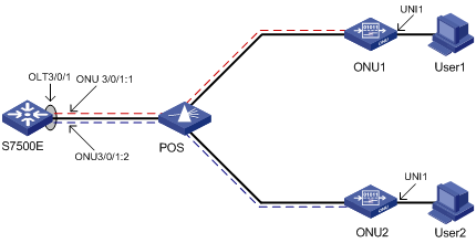
Bind ONU 3/0/1:1 to ONU 1, whose MAC address is 000f-e200-0031, and ONU 3/0/1:2 to ONU 2, whose MAC address is 000f-e200-3749. ONU 1 and ONU 2 have the same extended OAM version of 2.
Network diagram
Figure 3-1 Network diagram for ONU port-to-ONU binding configuration
Configuration procedure
# Configure the OUI and extended OAM version number list.
<Sysname> system-view
System View: return to User View with Ctrl+Z.
[Sysname] ftth
[Sysname-ftth] epon-parameter ouilist oui 000fe2 oam-version 2 slot 3
[Sysname-ftth] quit
# Create ONU ports ONU 3/0/1:1 and ONU 3/0/1:2. Bind ONU 3/0/1:1 to the ONU 1 and ONU 3/0/1:2 to ONU 2.
[Sysname] interface olt 3/0/1
[Sysname-Olt3/0/1] using onu 1 to 2
[Sysname-Olt3/0/1] quit
[Sysname] interface onu 3/0/1:1
[Sysname-Onu3/0/1:1] bind onuid 000f-e200-0031
[Sysname-Onu3/0/1:1] quit
[Sysname] interface onu 3/0/1:2
[Sysname-Onu3/0/1:2] bind onuid 000f-e200-3749
# When the two ONUs are up, display the binding information of the ONUs.
<Sysname> display onuinfo interface Olt 3/0/1
ONU Mac Address LLID Dist(M) Port Board/Ver Sft/Epm State Aging
000f-e200-0031 1 <50 Onu3/0/1:1 ET704-A-L/B 110/100 Up N/A
000f-e200-3749 2 <50 Onu3/0/1:2 ET704-A-L/B 110/100 Up N/A
--- 2 entries found ---
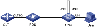
ONU RSTP Configuration Example
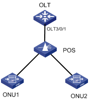
Network requirements
l A user PC is attached to UNI 1. If UNI 2 and UNI 3 are interconnected by mistake while RSTP is disabled on the ONU, broadcast storm will occur between UNI 2 and UNI 3 when the user pings an IP address for which no ARP entry exists on the PC.
l Enabling RSTP on the ONU can suppress such a problem.
Network diagram
Figure 3-2 Network diagram for ONU RSTP configuration
Configuration procedure
# Enable RSTP on the ONU to suppress the broadcast storm between UNI 2 and UNI 3.
<Sysname> system-view
[Sysname] interface onu 3/0/1:1
[Sysname-Onu3/0/1:1] onu-protocol stp enable
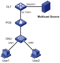
Multicast Configuration Example (in IGMP Snooping Mode)
Network requirements
l Connect Ethernet 2/0/1 of the switch with a multicast source, and connect port OLT 3/0/1 of the OLT with an ONU, which is bound to ONU 3/0/1:1, through an optical splitter. Attach two hosts, User 1 and User 2, to ports UNI 1 and UNI 2 respectively.
l It is required that User 1 has access to channels from 225.1.2.1 to 225.1.2.255, and User 2 has access to channels from 225.1.3.1 to 225.1.3.255.
Network diagram
Figure 3-3 Network diagram for multicast configuration (in IGMP snooping mode)
Configuration procedure
# Map the multicast addresses to multicast VLANs.
<Sysname> system-view
[Sysname] ftth
[Sysname-ftth] multicast vlan-id 1002 dest-ip 225.1.2.1 to 225.1.2.255
[Sysname-ftth] multicast vlan-id 1003 dest-ip 225.1.3.1 to 225.1.3.255
[Sysname-ftth] quit
# Enable IGMP snooping globally.
[Sysname] igmp-snooping
[Sysname-igmp-snooping] quit
# Enable IGMP snooping in VLAN 1002 and VLAN 1003.
[Sysname] vlan 1002
[Sysname-vlan1002] igmp-snooping enable
[Sysname-vlan1002] quit
[Sysname] vlan 1003
[Sysname-vlan1003] igmp-snooping enable
[Sysname-vlan1003] quit
# Configure the multicast mode of the ONU as IGMP snooping.
[Sysname-Onu3/0/1:1] multicast-mode igmp-snooping
# Assign UNI 1 to multicast VLAN 1002 and UNI 2 to multicast VLAN 1003, and configure the ONU as a Trunk port (to allow the packets of all the VLANs to pass through the port).
[Sysname-Onu3/0/1:1] uni 1 multicast vlan 1002
[Sysname-Onu3/0/1:1] uni 2 multicast vlan 1003
[Sysname-Onu3/0/1:1] port link-type trunk
# Configure UNI 1 and UNI 2 to remove the multicast VLAN tags from downlink multicast packets.
[Sysname-Onu3/0/1:1] uni 1 multicast-strip-tag enable
[Sysname-Onu3/0/1:1] uni 2 multicast-strip-tag enable
[Sysname-Onu3/0/1:1] quit
# Configure the link type of OLT 3/0/1 as hybrid, allow the packets of VLAN 1002 and VLAN 1003 to pass through OLT 3/0/1, and add tags to the VLAN 1002 and VLAN 1003 packets sent by OLT 3/0/1.
[Sysname] interface olt 3/0/1
[Sysname-Olt3/0/1] port link-type hybrid
[Sysname-Olt3/0/1] port hybrid vlan 1002 1003 tagged
# Configure Ethernet 2/0/1 as a Trunk port, and permit the packets of VLAN 1002 and VLAN 1003 to pass.
[Sysname] interface Ethernet2/0/1
[Sysname-Ethernet2/0/1] port link-type trunk
[Sysname-Ethernet2/0/1] port trunk permit vlan 1002 1003
Multicast Configuration Example (in Multicast Control Mode)
Network requirements
Connect Ethernet 2/0/1 of the switch with a multicast source, and connect port OLT 3/0/1 of the OLT with an ONU, which is bound to ONU 3/0/1:1, through an optical splitter. Attach two hosts, User 1 and User 2, to ports UNI 1 and UNI 2 respectively.
It is required that User 1 and User 2 have different access rights to Channel 1 (225.1.1.1) and Channel 1 (225.1.2.1):
l User 1 has full access to Channel 1 and 60-second preview access to Channel 2.
l User 2 has access to Channel 2 only.
Network diagram
Figure 3-4 Network diagram for multicast configuration (in multicast control mode)

Configuration procedure
# Map the multicast addresses to multicast VLANs.
<Sysname> system-view
[Sysname] ftth
[Sysname-ftth] multicast vlan-id 1002 dest-ip 225.1.1.1
[Sysname-ftth] multicast vlan-id 1003 dest-ip 225.1.2.1
[Sysname-ftth] quit
# Enable IGMP snooping globally.
[Sysname] igmp-snooping
[Sysname-igmp-snooping] quit
# Enable IGMP snooping in VLAN 1002 and VLAN 1003.
[Sysname] vlan 1002
[Sysname-vlan1002] igmp-snooping enable
[Sysname-vlan1002] vlan 1003
[Sysname-vlan1003] igmp-snooping enable
[Sysname-vlan1003] quit
# Configure the multicast mode of the ONU as the multicast control mode.
[Sysname-Onu3/0/1:1] multicast-mode multicast-control
# Configure UNI 1 to allow the user attached to it to access Channel 1 and to preview Channel 2 for only 60 seconds, and configure the port to remove the multicast VLAN tags from downlink multicast packets.
[Sysname-Onu3/0/1:1] uni 1 multicast-control multicast-address 225.1.1.1 rule permit
[Sysname-Onu3/0/1:1] uni 1 multicast-control multicast-address 225.1.2.1 rule preview time-slice 1
[Sysname-Onu3/0/1:1] uni 1 multicast-strip-tag enable
# Configure UNI 2 to allow the user attached to it to access Channel 2 only, and configure the port to remove the multicast VLAN tags from downlink multicast packets.
[Sysname-Onu3/0/1:1] uni 2 multicast-control multicast-address 225.1.1.1 rule deny
[Sysname-Onu3/0/1:1] uni 2 multicast-control multicast-address 225.1.2.1 rule permit
[Sysname-Onu3/0/1:1] uni 2 multicast-strip-tag enable
# Configure the ONU port as a Trunk port (to allow the packets of all the VLANs to pass through the port).
[Sysname-Onu3/0/1:1] port link-type trunk
# Configure the link type of OLT 3/0/1 as hybrid, allow the packets of VLAN 1002 and VLAN 1003 to pass through OLT 3/0/1, and add tags to the VLAN 1002 and VLAN 1003 packets sent by OLT 3/0/1.
[Sysname] interface olt 3/0/1
[Sysname-Olt3/0/1] port link-type hybrid
[Sysname-Olt3/0/1] port hybrid vlan 1002 1003 tagged
# Configure Ethernet 2/0/1 as a Trunk port, and permit the packets of VLAN 1002 and VLAN 1003 to pass through the port.
[Sysname] interface Ethernet2/0/1
[Sysname-Ethernet2/0/1] port link-type trunk
[Sysname-Ethernet2/0/1] port trunk permit vlan 1002 1003
ONU Update Configuration Example
Network requirements
l An S7500E switch at the city TV & broadcasting central office (CO) has 12 OLT ports connected to 150 type-A ONUs.
l The type-A ONU vendor recently released an enhanced software version 110 for type-A ONUs. This version solves some software bugs found in the previous version 109 and provides some new functions.
l The city office wants to update all the ONUs. District C branch office (connected to OLT 3/0/1) has 20 type-A ONUs under it. The network administrator believes version 109 can meet the current requirements and has worked normally. Thus, the network administrator asks to use version 110 on a trial basis in the branch office building (ONU 3/0/1:1 is bound with type-A ONUs for FTTB access to the building) and use version 109 for other ONUs.
Network diagram
Figure 3-5 Network diagram for ONU update
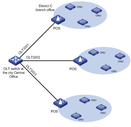
![]()
For a simplified network diagram, the figure above shows only three of the OLT ports.
Configuration procedure
# Upload update files a110.app and a109.app to the master SRPU and slave SRPU of the switch. For the detailed procedure, see the parts discussing software maintenance in H3C S7500E Series Ethernet Switches Installation Manual.
# Update all the attached type-A ONUs to version 109 in OLT 3/0/1 port view.
[Sysname] interface olt 3/0/1
[Sysname-Olt3/0/1] update onu filename a109.app
Update flash:/ a109.app?[Y/N]:y
Info: Download file to onu may take a long time, please wait...
Please wait while the firmware is being burnt, and check the software version after re-registration!
[Sysname-Olt3/0/1] quit
# Update the type-A ONUs corresponding to ONU 3/0/1:1 in District C branch office building to version 110.
[Sysname] interface onu 3/0/1:1
[Sysname-Onu3/0/1:1] update onu filename a110.app
Update flash:/ a110.app?[Y/N]:y
Info: Download file to onu may take a long time, please wait...
Please wait while the firmware is being burnt, and check the software version after re-registration!
[Sysname-Onu3/0/1:1] quit
# Update all the type-A ONUs attached to the S7500E switch to version 110.
<Sysname> system-view
[Sysname] ftth
[Sysname-ftth] update onu onu-type a filename a110.app
UNI Port Configuration Task List
![]()
If an H3C EC1001 inserted with a subcard serves as an ONU, a UNI port here refers to the internal port connecting the subcard to the EC1001, but not the Ethernet port of the EC1001.
Complete these tasks to configure a UNI port:
|
Task |
Remarks |
|
Optional |
|
|
Optional |
|
|
Optional |
|
|
Optional For H3C ONUs only |
|
|
Optional |
UNI Port Basic Configuration
l Duplex mode of a UNI: When a UNI works in full duplex mode, it can send and receive packets simultaneously. When a UNI works in half duplex mode, it can either send or receive packets at a time. When a UNI works in auto-negotiation mode, the duplex mode of the UNI is determined through negotiation by both ends.
l Flow control for UNIs: If the flow control function is enabled for both the UNIs and the remote device, the ONU will send messages to notify the remote device to stop sending packets temporarily when congestion occurs on the ONU, thus avoiding packet loss.
l MDI mode for UNIs: The MDI mode for UNIs can be crossover or straight-through.
l UNI port rate: You can set the UNI port rate. When the rate of a UNI is set to the auto-negotiation mode, the operating rate of the UNI is negotiated by the local port and the remote port.
l Auto-negotiation on a UNI: You can configure auto-negotiation on a UNI to enable both ends to auto-negotiate the duplex mode, cable type, and port rate. After forced auto-negotiation is enabled, the UNI port will restart the auto-negotiation.
Table 4-1 UNI Port Basic Configuration
|
To do... |
Use the command... |
Remarks |
|
Enter system view |
system-view |
— |
|
Enter ONU port view |
interface onu interface-number |
— |
|
Configure a description for a UNI |
uni uni-number description text |
Optional By default, no description is configured for a UNI. |
|
Shut down a UNI |
uni uni-number shutdown |
Optional By default, a UNI port is enabled. |
|
Configure the duplex mode for a UNI |
uni uni-number duplex { full | half | auto } |
Optional By default, a UNI port is in the full duplex mode. |
|
Enable flow control for a UNI |
uni uni-number flow-control |
Required By default, flow control is disabled for a UNI port. |
|
Configure the MDI mode for a UNI port |
uni uni-number mdi { across | auto | normal } |
Optional Be default, the MDI mode for a UNI port is auto. |
|
Configure the port rate for a UNI port |
uni uni-number speed { 10 | 100 | auto } |
Optional By default, the UNI port rate is 100Mbps. |
|
Enable auto-negotiation for a UNI port |
uni uni-number auto-negotiation |
Optional By default, auto-negotiation is enabled on a UNI port. |
|
Force a UNI port to restart auto-negotiation |
uni uni-number restart auto-negotiation |
Optional This command takes effect only when auto-negotiation is enabled on the UNI port. |
![]()
When auto-negotiation is enabled on a UNI port, you cannot configure the duplex mode, MDI mode, or rate of the UNI port.
Configuring the VLAN Operation Mode for a UNI
The VLAN operation modes for the Ethernet packets on a UNI are: transparent, tag, and translation.
Transparent mode
The transparent mode is suitable for situations where the user-end family gateway or switch is provided and managed by the operator and the VLAN tags generated by the family gateway or switch are trusted. In transparent mode, an ONU transparently forwards the received uplink Ethernet packets (regardless of whether the Ethernet packets contain VLAN tags or not) to the OLT without changing them. Downlink Ethernet packets are also forwarded transparently. Table 4-2 describes the detailed packet processing in this mode.
Tag mode
Tag mode is suitable for situations where the VLAN tags generated by the user-end family gateway or switch are not trusted. To enable the operator to centrally manage and control the VLANs of the service packets entering the network, network-layer VLAN tags need to be added to the packets. Table 4-2 describes the detailed packet processing in this mode.
Translation mode
In translation mode, an ONU translates the VLAN tag added by the user (The user's VID may not be for the user only, as some other users in the same EPON system may also use the same VID) into a unique network-side VLAN tag. Table 4-2 describes the packet processing by an ONU in translation mode.
Table 4-2 Packet processing in the three VLAN operation modes
|
VLAN operation mode |
Direction |
With or without VLAN tag |
Packet processing |
|
VLAN transparent transmission mode |
Uplink |
Tagged |
The UNI port forwards the frame without changing it. |
|
Untagged |
|||
|
Downlink |
Tagged |
||
|
Untagged |
|||
|
VLAN tagging mode |
Uplink |
Tagged |
The UNI port drops the frame. |
|
Untagged |
The UNI port tags the frame with the PVID tag and then forwards it. |
||
|
Downlink |
Tagged |
The ONU forwards the frame to the corresponding UNI port according to the VLAN ID in the frame’s VLAN tag and then removes the VLAN tag. |
|
|
Untagged |
The UNI port drops the frame. |
||
|
VLAN translation mode |
Uplink |
Tagged |
l If the VLAN ID in the frame’s VLAN tag matches a VLAN translation entry configured on the UNI port, the UNI port replaces this VLAN ID with the corresponding VLAN ID in the matched VLAN translation entry and then forwards the frame. l If the VLAN ID in the frame’s VLAN tag does not match any VLAN translation entry, the UNI port drops the frame. |
|
Untagged |
The UNI port tags the frame with its PVID tag and then forwards it. |
||
|
Downlink |
Tagged |
l If the VLAN ID in the frame’s VLAN tag matches a VLAN translation entry configured on the UNI port, the UNI port replaces this VLAN ID with the corresponding VLAN ID in the matched VLAN translation entry and then forwards the frame. l If the VLAN ID in the frame’s VLAN tag is the UNI port’s PVID, the UNI port removes the frame’s VLAN tag and then forwards the frame. l If the VLAN ID in the frame’s VLAN tag does not match any VLAN translation entry, the UNI port drops the frame. |
|
|
Untagged |
The UNI port drops the frame. |
Follow these steps to configure the VLAN operation mode for a UNI:
|
To do... |
Use the command... |
Remarks |
|
|
Enter system view |
system-view |
— |
|
|
Enter ONU port view |
interface onu interface-number |
— |
|
|
Configure the VLAN operation mode of a UNI port |
Transparent mode |
uni uni-number vlan-mode transparent |
Optional The default mode is transparent. |
|
Tag mode |
uni uni-number vlan-mode tag vlanid [ priority priority-value ] |
||
|
Translation mode |
uni uni-number vlan-mode translation pvid pvid [ priority priority ] { oldvid to newvid } &<1-15> |
||
![]()
If all ONU ports under an OLT port are access ports, you must set the VLAN operation mode of their UNI ports to transparent to ensure that the packets received on the ONU ports and the end-user PCs are untagged packets.
Configuring Fast-Leave Processing for a UNI
With the fast-leave processing feature enabled, when the ONU receives an IGMP leave message from a host announcing its leaving a multicast group, the ONU immediately deletes that port from the outgoing port list of the forwarding table. After that, when receiving IGMP group-specific queries for that multicast group, the ONU will not forward them to that port.
If only one host is attached to a port on the ONU, fast-leave processing helps improve bandwidth and resource usage.
Follow these steps to configure fast-leave processing for a UNI:
|
To do... |
Use the command... |
Remarks |
|
Enter system view |
system-view |
— |
|
Enter ONU port view |
interface onu interface-number |
— |
|
Enable fast-leave processing on a UNI |
uni uni-number igmp-snooping fast-leave |
Required By default, fast-leave processing is disabled on a UNI. |
![]()
l Before performing this configuration, make sure the ONU works in IGMP Snooping mode. For related configurations, refer to Configuring the Multicast Mode of the ONU.
l The fast-leave processing feature is effective for IGMPv2 or IGMPv3 clients only.
l If fast leave processing is enabled for a port to which more than one host is attached, when one host leaves a multicast group, the other hosts attached to the port and listening to the same multicast group will fail to receive multicast data.
Configuring Port Isolation for a UNI
This task adds UNIs to an isolation group to achieve Layer-2 data isolation (that is, UNIs in an isolation group cannot forward packets to each other). This improves network security and allows for flexible networking schemes.
Follow these steps to configure port isolation for a UNI:
|
To do... |
Use the command... |
Remarks |
|
|
Enter system view |
system-view |
— |
|
|
Enter ONU port view |
interface onu interface-number |
— |
|
|
Configure UNI port isolation |
Configure port isolation for all UNIs |
onu port-isolate enable |
Required Use either command By default, a UNI port is not in any isolation group. |
|
Configure port isolation for the specified UNI |
uni uni-number port-isolate |
||
![]()
Only one isolation group can be created on an ONU device, and there is no limit on the number of ports in an isolation group.
Displaying and Maintaining UNI Port Configuration
|
To do... |
Use the command... |
Remarks |
|
Display the information about the current status of a UNI |
display uni-information uni-number |
Available in ONU port view |
|
Clear the packet statistics information for a UNI |
reset counters uni [ uni-number ] |
Available in ONU port view |
![]()
l The above commands take effect on H3C ONUs only.
l The above commands work only when the ONU is online.
Introduction to Alarm
Sampling and Alarms
Sampling means the system retrieves statistics data at the sampling interval
At the alarm monitor interval, the system samples the alarm variables and will trigger an alarm if the value of a variable exceeds its alarm threshold. Alarm information can be output to the network management system or alarm buffer by configuring the information center.
The alarms can be global alarms, OLT port alarms, or ONU port alarms.
l When an alarm configuration command is executed in FTTH view, the command takes effect on all the OLT ports and all the ONUs attached to the OLT ports.
l When an alarm configuration command is executed in OLT port view, the command takes effect on the current OLT port and all the ONUs attached to the OLT port.
l When an alarm configuration command is executed in ONU port view, the command takes effect only on the ONU corresponding to the current ONU port.
Alarm Configuration Task List
Complete the following tasks to configure alarms:
|
Task |
Remarks |
|
|
Optional |
||
|
Alarm configuration |
Optional |
|
|
Optional |
||
|
Optional |
||
|
Optional |
||
Enabling Alarm Monitoring
Alarm monitoring function takes effect only when statistics sampling function is enabled. This is because no alarm information can be generated without the average value of sampled statistics.
Follow these steps to enabling sampling and alarm monitoring function:
|
To do... |
Use the command... |
Remarks |
|
|
Enter system view |
system-view |
— |
|
|
Enter FTTH view |
ftth |
— |
|
|
Configure the statistics sampling function |
Enable the statistics sampling function |
sample enable |
Optional Enabled by default |
|
Configure the statistics sampling interval |
timer sample seconds |
Optional 4 seconds by default |
|
|
Configure the alarm monitoring function |
Enable alarm monitoring function for the system |
monitor enable |
Optional Enabled by default |
|
Configure the alarm monitor period |
timer monitor seconds |
Optional 80 seconds by default |
|
Configuring Global Alarms
Follow these steps to configure global alarms:
|
To do... |
Use the command... |
Remarks |
|
Enter system view |
system-view |
— |
|
Enter FTTH view |
ftth |
— |
|
Enable the software error alarm function |
alarm software-error enable |
Optional The system generates a software error alarm when a signal error, Data Access (DA) error, or memory allocation failure occurs. By default, this function is enabled. |
|
Enable the bit error rate alarm function |
alarm bit-error-rate enable |
Optional When the total number of error bits or bit error rate of the data transferred between the OLT and ONUs exceeds the alarm threshold, a bit error rate alarm occurs. By default, this function is enabled. |
|
Configure the monitor direction and threshold for bit error rate alarms |
alarm bit-error-rate { direction { uplink | downlink | up-down-link} | threshold threshold }* |
Optional By default, the monitor direction is up-down-link, and the alarm threshold of bit error rate is 10 (the unit is 10-9). |
|
Enable the port bit error rate alarm function |
alarm port bit-error-rate enable |
Optional When both the total number of error bits and bit error rate of the data transferred between the OLT and ONUs exceed the alarm thresholds, a port bit error rate alarm occurs. By default, this function is enabled. |
|
Enable the device fatal error alarm function |
alarm device-fatal-error enable |
Optional By default, this function is enabled. |
|
Enable the frame error rate alarm function |
alarm frame-error-rate enable |
Optional When the total number of error frames or the error frame rate of the data transferred between the OLT and ONUs exceeds the alarm threshold, a frame error rate alarm occurs. By default, this function is enabled. |
|
Configure the monitor direction and threshold for frame error rate alarms |
alarm frame-error-rate { direction { uplink | downlink | up-down-link} | threshold threshold } * |
Optional By default, the monitor direction is up-down-link, and the threshold of frame error rate alarms is 1 (the unit is 10-9). |
|
Enable the LLID mismatch frame alarm function |
alarm llid-mismatch enable |
Optional The system generates an LLID mismatch frame alarm when the time slots are used in disorder, that is, an ONU uses another ONU's time slot to forward data. By default, this function is disabled. |
|
Configure the threshold for LLID mismatch frame alarms |
alarm llid-mismatch threshold threshold |
Optional By default, the threshold of LLID mismatch alarms is 5000 frames. |
|
Enable the local stable alarm function |
alarm local-stable enable |
Optional The system generates a local stable alarm when an ONU misuse occurs in the system, for example, when an OAM 2.0 ONU and an OAM 3.3 ONU are mixed in the same system. (All ONUs in the same system must adopt the same OAM version). This alarm is generated at the OLT side. By default, this function is enabled. |
|
Enable the critical event alarm function |
alarm oam critical-event enable |
Optional The system generates a critical event alarm when one of the following critical events occurs: local link fault and dying gasp. |
|
Enable the dying gasp alarm function |
alarm oam dying-gasp enable |
Optional The system generates a dying gasp alarm when a system error, a data loading error, or any other nonreversible errors occur. |
|
Enable the error frame period alarm function |
alarm oam error-frame-period enable |
Optional The system generates an error frame period alarm when the number of error frames in a specific period (that is, the window size) exceeds the corresponding predefined threshold. By default, this function is enabled. |
|
Configure the window size and threshold for error frame period alarms |
alarm oam error-frame-period { window window | threshold threshold } * |
Optional When the alarm threshold is set to 0, a lot of alarms are generated immediately. Since alarm events are carried in the OAM packets, a lot of OAM packets are generated. In this case, OAM packets may be lost. By default, the window size is 1 second, and the alarm threshold is 20 frames. |
|
Enable the error frame alarm function |
alarm oam error-frame enable |
Optional The system generates an error frame alarm when the number of error frames in a specific time period (that is, the window size) exceeds the corresponding predefined threshold. By default, this function is enabled. |
|
Configure the window size and threshold for error frame alarms |
alarm oam error-frame { window window | threshold threshold } * |
Optional When the alarm threshold is set to 0, a lot of alarms are generated immediately. Since alarm events are carried in the OAM packets, a lot of OAM packets are generated. In this case, OAM packets may be lost. By default, the window size is 10 seconds, and the alarm threshold is 20 frames. |
|
Enable the error frame seconds summary alarm function |
alarm oam error-frame-seconds-summary enable |
Optional The system generates an error frame seconds summary alarm when the number of error frame seconds (in an error frame second, at least one error frame occurs) in a specific time period (for example, 1 minute) exceeds the corresponding predefined threshold. By default, this function is enabled. |
|
Configure the window size and threshold for error frame seconds summary alarms |
alarm oam error-frame-seconds-summary { window window | threshold threshold } * |
Optional By default, the window size is 600 (in unit of 100 ms), and the alarm threshold is 1 second. |
|
Enable the error symbol period alarm function |
alarm oam error-symbol-period enable |
Optional The system generates an error symbol period alarm when the number of error frames in a specific period (that is, the window size) exceeds the corresponding predefined threshold. By default, this function is enabled. |
|
Configure the window size and thresholds for error symbol period alarms |
alarm oam error-symbol-period { window-high windowhigh | window-low windowlow | threshold-high thresholdhigh | threshold-low thresholdlow } * |
Optional When both the upper limit and the lower limit of the alarm threshold are set to 0, a lot of alarms are generated immediately. Since alarm events are carried in the OAM packets, a lot of OAM packets are generated. In this case, OAM packets may be lost. The window size and threshold values specified in this command comprise two parts, the significant part and the insignificant part, both of which are 16 bits in length. By default, the window size is 1 second, and the alarm threshold is 20 bytes. |
|
Enable the local link fault alarm function |
alarm oam local-link-fault enable |
Optional The system generates a local link fault alarm when the inbound direction of the local data terminal becomes faulty. |
|
Enable the registration error alarm function |
alarm registration-error enable |
Optional The system generates a registration error alarm when an error occurs during the registration of an ONU. By default, this function is enabled. |
|
Enable the remote stable alarm function |
alarm remote-stable enable |
Optional The system generates a remote stable alarm when an ONU misuse occurs in the system, for example, when an OAM 2.0 ONU and an OAM 3.3 ONU are mixed in the same system. (All ONUs in the same system must adopt the same OAM version). This alarm is generated at the ONU side and will be reported to the OLT. By default, this function is enabled. |
|
Enable the OAM vendor-specific alarm function |
alarm oam-vendor-specific enable |
Optional This alarm is customized by vendors. By default, this function is enabled. |
|
Enable the ONU over limitation alarm function |
alarm onu-over-limitation enable |
Optional The system generates an ONU over limitation alarm when the total number of ONUs connected with the OLT exceeds the limit. By default, this function is enabled. |
Configuring Alarms on an OLT Port
Follow these steps to configure alarms on an OLT port:
|
To do... |
Use the command... |
Remarks |
|
Enter system view |
system-view |
— |
|
Enter OLT port view |
interface olt interface-number |
— |
|
Enable the bit error rate alarm function |
alarm bit-error-rate enable |
Optional The system generates a bit error rate alarm when the total number of error bits or bit error rate of the data transferred between the OLT and ONUs exceeds the alarm threshold. By default, this function is enabled. |
|
Configure the monitor direction and threshold for bit error rate alarms |
alarm bit-error-rate { direction { uplink | downlink | up-down-link} | threshold threshold }* |
Optional By default, the monitor direction is up-down-link, and the threshold of bit error rate alarms is 10 (the unit is 10-9). |
|
Enable the port bit error rate alarm function |
alarm port bit-error-rate enable |
Optional When both the total number of error bits and bit error rate of the data transferred between the OLT and ONUs exceed the alarm thresholds, a port bit error rate alarm occurs. By default, this function is enabled. |
|
Enable the device fatal error alarm function |
alarm device-fatal-error enable |
Optional By default, this function is enabled. |
|
Enable the frame error rate alarm function |
alarm frame-error-rate enable |
Optional When the total number of error frames or the error frame rate of the data transferred between the OLT and ONUs exceeds the alarm threshold, a frame error rate alarm occurs. By default, this function is enabled. |
|
Configure the monitor direction and threshold for frame error rate alarms |
alarm frame-error-rate { direction { uplink | downlink | up-down-link } | threshold threshold } * |
Optional By default, the monitor direction is up-down-link, and the threshold of frame error rate alarms is 1 (the unit is 10-9). |
|
Enable the LLID mismatch frame alarm function |
alarm llid-mismatch enable |
Optional The system generates an LLID mismatch frame alarm when the time slots are used in disorder, that is, when an ONU uses another ONU's time slot to forward data. By default, this function is disabled. |
|
Configure the threshold of LLID mismatch frame alarms |
alarm llid-mismatch threshold threshold |
Optional 5000 frames by default |
|
Enable the local stable alarm function |
alarm local-stable enable |
Optional The system generates a local stable alarm when an ONU misuse occurs in the system, for example, when an OAM 2.0 ONU and an OAM 3.3 ONU are mixed in the same system. (All ONUs in the same system must adopt the same OAM version). A local stable alarm is generated by the OLT side. By default, this function is enabled. |
|
Enable the critical event alarm function |
alarm oam critical-event enable |
Optional The system generates a critical event alarm when one of the following critical events occurs: local link fault and dying gasp. |
|
Enable the dying gasp alarm function |
alarm oam dying-gasp enable |
Optional The system generates a dying gasp alarm when a system error, a data loading error or any other nonreversible error occurs. |
|
Enable the error frame period alarm function |
alarm oam error-frame-period enable |
Optional The system generates an error frame period alarm when the number of error frames in a specific period (that is, the window size) exceeds the corresponding predefined threshold. By default, this function is enabled. |
|
Configure the window size and threshold for error frame period alarms |
alarm oam error-frame-period { window window | threshold threshold } * |
Optional When the alarm threshold is set to 0, a lot of alarms are generated immediately. Since alarm events are carried in the OAM packets, a lot of OAM packets are generated. In this case, OAM packets may be lost. By default, the window size is 1 second, and the alarm threshold is 20 frames. |
|
Enable the error frame alarm function |
alarm oam error-frame enable |
Optional The system generates an error frame alarm when the number of error frames in a specific time period (that is, the window size) exceeds the corresponding predefined threshold. By default, this function is enabled. |
|
Configure the window size and threshold for error frame alarms |
alarm oam error-frame { window window | threshold threshold } * |
Optional When the alarm threshold is set to 0, a lot of alarms are generated immediately. Since alarm events are carried in the OAM packets, a lot of OAM packets are generated. In this case, OAM packets may be lost. By default, the window size is 10 seconds, and the alarm threshold is 20 frames. |
|
Enable the error frame seconds summary alarm function |
alarm oam error-frame-seconds-summary enable |
Optional The system generates an error frame seconds summary alarm when the number of error frame seconds (in an error frame second, at least one error frame occurs) in a specific time period (for example, 1 minute) exceeds the corresponding predefined threshold. By default, this function is enabled. |
|
Configure the window size and threshold for error frame seconds summary alarms |
alarm oam error-frame-seconds-summary { window window | threshold threshold } * |
Optional By default, the window size is 600 (in unit of 100 ms), and the alarm threshold is 1 second. |
|
Enable the error symbol period alarm function |
alarm oam error-symbol-period enable |
Optional The system generates an error symbol period alarm when the number of error frames in a specific period (that is, the window size) exceeds the corresponding predefined threshold. By default, this function is enabled. |
|
Configure the window size and thresholds for error symbol period alarms |
alarm oam error-symbol-period { window-high windowhigh | window-low windowlow | threshold-high thresholdhigh | threshold-low thresholdlow } * |
Optional When both the upper limit and the lower limit of the alarm threshold are set to 0, a lot of alarms are generated immediately. Since alarm events are carried in the OAM packets, a lot of OAM packets are generated. In this case, OAM packets may be lost. The window size and threshold values specified in this command comprise two parts, a significant part and an insignificant part, both 16 bits in length. By default, the window size is 1 second, and the alarm threshold is 20 bytes. |
|
Enable the local link fault alarm function |
alarm oam local-link-fault enable |
Optional The system generates a local link fault alarm when the inbound direction of the local data terminal becomes faulty. |
|
Enable the registration error alarm function |
alarm registration-error enable |
Optional The system generates a registration error alarm when an error occurs during the registration of an ONU. By default, this function is enabled. |
|
Enable the remote stable alarm function |
alarm remote-stable enable |
Optional The system generates a remote stable alarm when an ONU misuse occurs in the system, for example, when an OAM 2.0 ONU and an OAM 3.3 ONU are mixed in the same system. (All ONUs in the same system must adopt the same OAM version). This alarm is generated at the ONU side and will be reported to the OLT. By default, this function is enabled. |
|
Enable the OAM vendor-specific alarm function |
alarm oam-vendor-specific enable |
Optional This alarm is customized by vendors. By default, this function is enabled. |
|
Enable the ONU over limitation alarm function |
alarm onu-over-limitation enable |
Optional The system generates an ONU over limitation alarm when the total number of ONUs connected with the OLT exceeds the limit. By default, this function is enabled. |
Configuring Alarms on an ONU Port
Follow these steps to configure alarms on an ONU port:
|
To do... |
Use the command... |
Remarks |
|
Enter system view |
system-view |
— |
|
Enter ONU port view |
interface onu interface-number |
— |
|
Enable the error symbol period alarm function |
alarm oam error-symbol-period enable |
Optional The system generates an error symbol period alarm when the number of error frames in a specific period (that is, the window size) exceeds the corresponding predefined threshold. By default, this function is enabled. |
|
Enable the error frame period alarm function |
alarm oam error-frame-period enable |
Optional The system generates an error frame period alarm when the number of error frames in a specific period (that is, the window size) exceeds the corresponding predefined threshold. By default, this function is enabled. |
|
Configure the window size and threshold for error frame period alarms |
alarm oam error-frame-period { window window | threshold threshold } * |
Optional When the alarm threshold is set to 0, a lot of alarms are generated immediately. Since alarm events are carried in the OAM packets, a lot of OAM packets are generated. In this case, OAM packets may be lost. By default, the window size is 1 second, and the alarm threshold is 20 frames. |
|
Enable the error frame alarm function |
alarm oam error-frame enable |
Optional The system generates an error frame alarm when the number of error frames in a specific time period (that is, the window size) exceeds the corresponding predefined threshold. By default, this function is enabled. |
|
Configure the window size and threshold for error frame alarms |
alarm oam error-frame { window window | threshold threshold } * |
Optional When the alarm threshold is set to 0, a lot of alarms are generated immediately. Since alarm events are carried in the OAM packets, a lot of OAM packets are generated. In this case, OAM packets may be lost. By default, the window size is 10 second, and the alarm threshold is 20 frames. |
|
Enable the error frame seconds summary alarm function |
alarm oam error-frame-seconds-summary enable |
Optional The system generates an error frame seconds summary alarm when the number of error frame seconds (in an error frame second, at least one error frame occurs) in a specific time period (for example, 1 minute) exceeds the corresponding predefined threshold. By default, this function is enabled. |
|
Configure the window size and threshold for error frame seconds summary alarms |
alarm oam error-frame-seconds-summary { window window | threshold threshold } * |
Optional By default, the window size is 600 (in unit of 100 ms), and the alarm threshold is 1 second. |
|
Enable the port bit error rate alarm function |
alarm port bit-error-rate enable |
Optional When both the total number of error bits and the bit error rate of the data transferred between the OLT and ONUs exceed the alarm threshold, a port bit error rate alarm occurs. By default, this function is enabled. |
Displaying and Maintaining Alarm Configurations
|
To do... |
Use the command... |
Remarks |
|
Display the configuration information in FTTH view, OLT port view, or ONU port view |
display current-configuration [configuration ftth | interface interface-type interface-number ] |
Available in any view |
|
Display the configuration information in the current view |
display this |
Available in the current view |
|
Display alarm event records |
display trapbuffer [ reverse ] [ size buffersize ] |
Available in any view |
![]()
l Use the display this command to display the configuration in the current view. To display the alarm configurations in FTTH view, OLT port view, or ONU port view, you need to enter the corresponding view.
l Table 5-1 shows the relations between the views in which alarms are configured and the views in which alarm configurations are displayed.
l For details about the display trapbuffer command, see the part discussing information center in the command manual.
Table 5-1 Relations between the alarm command configuration views and alarm configuration display views
|
Alarm command configuration view |
Alarm configuration display view |
Remarks |
|
l FTTH view l OLT port view l ONU port view |
ONU port view |
For an alarm configuration command available in any of the three views, you can use the display this command in ONU port view to display the alarm configuration. |
|
l FTTH view l OLT port view |
OLT port view |
l For an alarm configuration command available in FTTH view and OLT port view, you can use the display this command in OLT port view to display the alarm configuration. l For an alarm configuration command available in OLT port view only, you can use the display this command in OLT port view to display the alarm configuration. |
|
OLT port view |
||
|
FTTH view |
FTTH view |
For an alarm configuration command available in FTTH view only, you can use the display this command in FTTH view to display the alarm configuration. |
OLT Port Features and Restrictions
Table 6-1 OLT port features
|
Feature |
Remarks |
Related section |
|
Basic parameters |
l Configuring an OLT port description string l Enabling/disabling an OLT port l Displaying and clearing port statistics information |
Port-related configuration |
|
Flow control |
Configuring flow control on an OLT port |
Port-related configuration |
|
Data storm suppression |
l Configuring broadcast suppression ratio on an OLT port l Configuring multicast suppression ratio on an OLT port l Configuring unknown unicast suppression ratio on an OLT port |
Port-related configuration |
|
Port link type |
l Setting the link type of an OLT port to Hybrid l Allowing the packets of the specified VLAN(s) to pass through the current Hybrid port l Setting the default VLAN ID for the Hybrid port |
VLAN configuration |
|
Port isolation |
Configuring OLT port isolation |
Port-related configuration |
|
Configuring OLT port trap |
SNMP-RMON configuration |
|
|
IGMP Snooping |
Configuring IPv4 multicast source port filtering on an OLT port |
Multicast protocol configuration |
|
MLD Snooping |
Configuring IPv6 multicast source port filtering on an OLT port |
Multicast protocol configuration |
|
QinQ |
l Configuring QinQ on an OLT port l Configuring user-side QinQ on an OLT port l Configuring network-side QinQ on an OLT port l Configure the TPID carried in operator VLAN tag |
QinQ-BPDU TUNNEL |
|
BPDU TUNNEL |
Configuring BPDU tunneling on an OLT port |
QinQ-BPDU TUNNEL |
|
Port mirroring |
Configuring OLT port mirroring |
Port mirroring |
|
QoS |
l Configuring port rate limit l Configuring traffic shaping l Configuring QoS policies l Configuring congestion management l Configuring port priority l Configuring the priority trust mode of a port l Configuring the QoS capability of an OLT l Configure priority mapping for downlink traffic of an ONU |
QoS configuration |
|
IP Source Guard |
Configuring IP Source Guard on an OLT port |
IP Source Guard configuration |
|
Smart Link |
Enabling receiving Flush packets |
Smart Link configuration |
![]()
l The priority configured for an OLT port (with the qos priority priority-value command) takes effect only when QinQ is enabled on the OLT port.
l After MAC authentication is enabled on an OLT port, the port directly discards the unicast packets that fail to pass the authentication, while the corresponding multicast table entries can be created on the device for multicast packets regardless of whether the multicast packets pass the authentication.
ONU Port Features and Restrictions
This section discusses the ONU port configurations with an S7500E switch working as an OLT device. The actual configurations depend on whether the ONUs attached to the OLT ports support the features. Assume UNI port mirroring can be configured in port view of ONU 3/0/1:1. This configuration, however, will not take effect if the ONUs attached to ONU 3/0/1:1 do not support port mirroring.
Table 6-2 ONU port features
|
Feature |
Remarks |
Reference |
|
Basic parameters |
l Configuring an ONU port description string l Enabling/disabling an ONU port l Configuring port up/down state suppression timers l Displaying and clearing port statistics information |
Port-related configuration |
|
Loopback test |
Configuring ONU port loopback test function |
Port-related configuration |
|
Port link type |
Configuring the link type and default VLAN ID for an ONU port |
VLAN configuration |
|
Port trap |
Configuring ONU port trap |
SNMP-RMON configuration |
|
MAC address table management |
l Adding or modifying MAC address entries on specific ONU ports l Configuring the maximum number of MAC addresses that can be learned on an ONU port |
MAC address table management configuration |
|
DHCP Snooping |
l Configuring DHCP snooping to support Option82 l Configuring the Option82 padding formats l Configuring a strategy for DHCP snooping to handle request packets containing Option82 l Configuring the padding format and contents of non-custom Circuit ID sub-options l Configuring the padding format and contents of non-custom Remote ID sub-options |
DHCP |
|
IGMP Snooping |
l Enabling fast-leaving processing l Configuring the maximum number of IPv4 multicast groups that can be joined on a port l Configuring IPv4 multicast group filtering l Configuring a port as a simulated host to join a multicast group l Configuring IPv4 multicast group replacement l Configuring static router/member ports |
|
|
MLD Snooping |
l Enabling fast-leaving processing l Configuring the maximum number of IPv6 multicast groups that can be joined on a port l Configuring IPv6 multicast group filtering l Configuring a port as a simulated host to join an IPv6 multicast group l Configuring IPv6 multicast group replacement l Configuring static router/member ports |
|
|
Port mirroring |
Configuring local UNI port mirroring |
Port Mirroring |
|
QoS |
l Configuring port priority l Configuring QoS policies l Configuring congestion management l Configuring the priority trust mode of a port l Configuring traffic classification and priority marking for uplink traffic of a UNI l Configure traffic policing for uplink/downlink traffic of a UNI |
QoS |
Table 6-3 Restrictions
|
Feature |
Restrictions |
|
Loopback test |
In an ONU remote loopback test, all packets forwarded downlink are untagged. If the VLAN operation mode is set to tag or translation for the corresponding UNI port, the test packets will be dropped and the loopback test will fail. |
|
QoS |
l When an ACL rule is referenced in a QoS policy, the action defined in the ACL rule (deny or permit) does not work. Instead, the action on the packets that match the ACL rule is determined by the traffic behavior defined in the QoS policy. l ONU ports support packet filtering based on source MAC address, destination MAC address, Ethernet type, VLAN ID, source IP address, destination IP address, source TCP port, and source UDP port only. l Source MAC address-based packet filtering on an ONU port works only on the uplink direction and supports a maximum of 32 ACL rules. l Destination MAC address-based packet filtering on an ONU port works on both uplink and downlink directions and supports a maximum of 32 ACL rules. l Ethernet type-based packet filtering on an ONU port supports a maximum of 30 ACL rules in the case of single-direction configuration and a maximum of 16 ACL rules for each direction when configured for both uplink and downlink directions. l VLAN ID-based packet filtering on an ONU port supports a maximum of 6 ACL rules for the uplink direction and a maximum 8 ACL rules for the downlink direction. l Source/destination IP address-based packet filtering on an ONU port supports a maximum of 24 ACL rules in the case of single-direction configuration and a maximum of 16 ACL rules for each direction when configured for both uplink and downlink directions. l Source TCP/UDP port-based packet filtering supports a maximum of 24 ACL rules in the case of single-direction configuration and a maximum of 32 ACL rules when configured for both uplink and downlink directions. |
![]()
As ONU ports are used for accessing, when the S7500E switch is configured as a DHCP Snooping device, do not connect a DHCP server to the ONU port.
