- Table of Contents
-
- 01-Access Volume
- 00-Access Volume Organization
- 01-Ethernet Interface Configuration
- 02-Link Aggregation Configuration
- 03-Port Isolation Configuration
- 04-Service Loopback Group Configuration
- 05-DLDP Configuration
- 06-Smart Link Configuration
- 07-LLDP Configuration
- 08-VLAN Configuration
- 09-GVRP Configuration
- 10-QinQ Configuration
- 11-BPDU Tunneling Configuration
- 12-VLAN Mapping Configuration
- 13-Ethernet OAM Configuration
- 14-Connectivity Fault Detection Configuration
- 15-EPON-OLT Configuration
- 16-MSTP Configuration
- 17-RRPP Configuration
- 18-Mirroring Configuration
- Related Documents
-
| Title | Size | Download |
|---|---|---|
| 07-LLDP Configuration | 159.76 KB |
Table of Contents
Performing Basic LLDP Configuration
Configuring the Parameters Concerning LLDPDU Sending
Configuring the Encapsulation Format for LLDPDUs
Configuring the Encapsulation Format of the Management Address
Displaying and Maintaining LLDP
LLDP Basic Configuration Example
CDP-Compatible LLDP Configuration Example
When configuring LLDP, go to these sections for information you are interested in:
l LLDP Configuration Task List
l Performing Basic LLDP Configuration
l Configuring the Encapsulation Format for LLDPDUs
l Configuring the Encapsulation Format of the Management Address
l Configuring CDP Compatibility
l Displaying and Maintaining LLDP
Introduction to LLDP
Background
In a heterogeneous network, it is important that different types of network devices from different vendors can discover one other and exchange configuration for interoperability and management sake. This calls for a standard configuration exchange platform.
To address the needs, the IETF drafted the Link Layer Discovery Protocol (LLDP) in IEEE 802.1AB. The protocol operates on the data link layer to exchange device information between directly connected devices. With LLDP, a device sends local device information (including its major functions, management IP address, device ID, and port ID) as TLV (type, length, and value) triplets in LLDPDUs to the directly connected devices, and at the same time, stores the device information received in LLDPDUs sent from the LLDP neighbors in a standard management information base (MIB). It allows a network management system to fast detect Layer-2 network topology change and identify what the change is.
![]()
For more information about MIBs, refer to SNMP Configuration in the System Volume.
LLDP Fundamental
LLDP operating mode
LLDP can operate in one of the following modes.
l TxRx mode. A port in this mode sends and receives LLDPDUs.
l Tx mode. A port in this mode only sends LLDPDUs.
l Rx mode. A port in this mode only receives LLDPDUs.
l Disable mode. A port in this mode does not send or receive LLDPDUs.
LLDP is initialized when an LLDP-enabled port changes to operate in another LLDP operating mode. To prevent LLDP from being initialized too frequently, LLDP undergoes a period before being initialized on an LLDP-enabled port when the port changes to operate in another LLDP operating mode. The period is known as initialization delay, which is determined by the re-initialization delay timer.
Sending LLDPDUs
An LLDP-enabled device operating in TxRx mode or Tx mode sends LLDPDUs to its directly connected devices periodically. It also sends LLDPDUs when the local configuration changes to inform the neighboring devices of the change timely. In any of the two cases, an interval exists between two successive operations of sending LLDPDUs. This prevents the network from being overwhelmed by LLDPDUs even if the LLDP operating mode changes frequently.
To enable the neighboring devices to be informed of the existence of a device or an LLDP operating mode change (from the disable mode to TxRx mode, or from the Rx mode to Tx mode) timely, a device can invoke the fast sending mechanism. In this case, the interval to send LLDPDUs changes to one second. After the device sends specific number of LLDPDUs, the interval restores to the normal. (A neighbor is discovered when a device receives an LLDPDU and no information about the sender is locally available.)
Receiving LLDPDUs
An LLDP-enabled port operating in TxRx mode or Rx mode checks the TLVs carried in every LLDP frame it receives for validity violation. If valid, the information is saved and an aging timer is set for it based on the time to live (TTL) TLV carried in the LLDPDU. If the TTL TLV is zero, the information is aged out immediately.
You can configure the TTL of locally sent LLDP frames to determine how long information about the local device can be saved on a neighbor device by setting the TTL multiplier. The TTL is expressed as follows:
TTL = Min (65535, (TTL multiplier × LLDPDU transmit interval))
As the expression shows, the TTL can be up to 65535 seconds. TTLs greater than it will be rounded down to 65535 seconds.
TLV Types
TLVs encapsulated in LLDPDUs fall into these categories: basic TLV, organization defined TLV, and MED (media endpoint discovery) related TLV. Basic TLVs are the base of device management. Organization specific TLVs and MED related TLVs are used for enhanced device management. They are defined in standards or by organizations and are optional to LLDPDUs.
Basic LLDP TLVs
Table 1-1 lists the basic LLDP TLV types that are currently in use.
|
Type |
Description |
Remarks |
|
End of LLDPDU TLV |
Marks the end of an LLDPDU. |
Required for LLDP |
|
Chassis ID TLV |
Carries the bridge MAC address of the sender |
|
|
Port ID TLV |
Carries the sending port. For devices that do not send MED TLVs, port ID TLVs carry sending port name. For devices that send MED TLVs, port ID TLVs carry the MAC addresses of the sending ports or bridge MAC addresses (if the MAC addresses of the sending ports are unavailable). |
|
|
Time To Live TLV |
Carries the TTL of device information |
|
|
Port Description TLV |
Carries Ethernet port description |
Optional to LLDP |
|
System Name TLV |
Carries device name |
|
|
System Description TLV |
Carries system description |
|
|
System Capabilities TLV |
Carries information about system capabilities |
|
|
Management Address TLV |
Carries the management address, the corresponding port number, and OID (object identifier). If the management address is not configured, it is the IP address of the interface of the VLAN with the least VLAN ID among those permitted on the port. If the IP address of the VLAN interface is not configured, IP address 127.0.0.1 is used as the management address. |
Organization defined LLDP TLVs
1) LLDP TLVs defined in IEEE802.1 include the following:
l Port VLAN ID TLV, which carries port VLAN ID.
l Port and protocol VLAN ID TLV, which carries port protocol VLAN ID.
l VLAN name TLV, which carries port VLAN name.
l Protocol identity TLV, which carries types of the supported protocols.
![]()
Currently, protocol identity TLVs can only be received on H3C devices.
2) IEEE 802.3 defined LLDP TLVs include the following:
l MAC/PHY configuration/status TLV, which carries port configuration, such as port speed, duplex state, whether port speed auto-negotiation is supported, the state of auto-negotiation, current speed , and current duplex state.
l Power via MDI TLV, which carries information about power supply capabilities.
l Link aggregation TLV, which carries the capability and state of link aggregation.
l Maximum frame size TLV, which carries the maximum frame size supported, namely, MTU (maximum transmission unit).
MED related LLDP TLVs
LLDP-MED TLVs provide multiple advanced applications for VoIP, such as basic configuration, network policy configuration, and address and directory management. LLDP-MED TLVs satisfy the voice device manufacturers’ requirements for cost-effectiveness, easy deployment, and easy management. In addition, LLDP-MED TLVs make deploying voice devices in Ethernet easier.
l LLDP-MED capabilities TLV, which carries the MED type of the current device and the types of the LLDP MED TLVs that can be encapsulated in LLDPDUs.
l Network policy TLV, which carries port VLAN ID, supported applications (such as voice and video services), application priority, and the policy adopted.
l Extended power-via-MDI TLV, which carries the information about the power supply capability of the current device.
l Hardware revision TLV, which carries the hardware version of an MED device.
l Firmware revision TLV, which carries the firmware version of an MED device.
l Software revision TLV, which carries the software version of an MED device.
l Serial number TLV, which carries the serial number of an MED device.
l Manufacturer name TLV, which carries the manufacturer name of an MED device.
l Model name TLV, which carries the model of an MED device.
l Asset ID TLV, which carries the asset ID of an MED device. Asset ID is used for directory management and asset tracking.
l Location identification TLV, which carries the location identification of a device. Location identification can be used in location-based applications.
![]()
For detailed information about LLDP TLV, refer to IEEE 802.1AB-2005 and ANSI/TIA-1057.
Protocols and Standards
l IEEE 802.1AB-2005, Station and Media Access Control Connectivity Discovery
l ANSI/TIA-1057, Link Layer Discovery Protocol for Media Endpoint Devices
LLDP Configuration Task List
Complete these tasks to configure LLDP:
|
Task |
Remarks |
|
|
Basic LLDP configuration |
Required |
|
|
Optional |
||
|
Optional |
||
|
Optional |
||
|
Optional |
||
|
Optional |
||
|
Configuring the Encapsulation Format of the Management Address |
Optional |
|
|
Optional |
||
|
Optional |
||
Performing Basic LLDP Configuration
Enabling LLDP
Follow these steps to enable LLDP:
|
To do… |
Use the command… |
Remarks |
|
|
Enter system view |
system-view |
— |
|
|
Enable LLDP globally |
lldp enable |
Required The default global state of LLDP is enabled. |
|
|
Enter Ethernet interface view/port group view |
Enter Ethernet interface view |
interface interface-type interface-number |
Either of the two is required. Configuration performed in Ethernet interface view applies to the current port only; configuration performed in port group view applies to all the ports in the corresponding port group. |
|
Enter port group view |
port-group manual port-group-name |
||
|
Enable LLDP |
lldp enable |
Optional By default, LLDP is enabled on a port. |
|
![]()
To make LLDP take effect, you need to enable it both globally and on the related ports.
Setting LLDP Operating Mode
Follow these steps to set LLDP operating mode:
|
To do… |
Use the command… |
Remarks |
|
|
Enter system view |
system-view |
— |
|
|
Set the initialization delay period |
lldp timer reinit-delay value |
Optional 2 seconds by default. |
|
|
Enter Ethernet interface view/port group view |
Enter Ethernet interface view |
interface interface-type interface-number |
Either of the two is required. Configuration performed in Ethernet interface view applies to the current port only; configuration performed in port group view applies to all the ports in the corresponding port group. |
|
Enter port group view |
port-group manual port-group-name |
||
|
Set the LLDP operating mode |
lldp admin-status { disable | rx | tx | txrx } |
Optional TxRx by default. |
|
Configuring LLDPDU TLVs
Follow these steps to configure LLDPDU TLVs:
|
To do… |
Use the command… |
Remarks |
|
|
Enter system view |
system-view |
— |
|
|
Set the TTL multiplier |
lldp hold-multiplier value |
Optional 4 by default. |
|
|
Enter Ethernet interface view/port group view |
Enter Ethernet interface view |
interface interface-type interface-number |
Either of the two is required. Configuration performed in Ethernet interface view applies to the current port only; configuration performed in port group view applies to all the ports in the corresponding port group. |
|
Enter port group view |
port-group manual port-group-name |
||
|
Enable LLDP TLV sending for specific types of LLDP TLVs |
lldp tlv-enable { basic-tlv { all | port-description | system-capability | system-description | system-name } | dot1-tlv { all | port-vlan-id | protocol-vlan-id [ vlanid ] | vlan-name [ vlan-id ] } | dot3-tlv { all | link-aggregation | mac-physic | max-frame-size | power } | med-tlv { all | capability | inventory | location-id { civic-address device-type country-code { ca-type ca-value } & < 1 – 10 > | elin-address tel-number } | network-policy | power-over-ethernet } } |
Optional By default, all types of LLDP TLVs except location identification TLV are sent. |
|
|
Specify the management address and specify to send the management address through LLDPDUs |
lldp management-address-tlv [ ip-address ] |
Optional By default, the management address is sent through LLDPDUs, and the management address is the IP address of the interface of the VLAN with the least VLAN ID among those permitted on the port. If the IP address of the VLAN interface is not configured, IP address 127.0.0.1 is used as the management address. Refer to VLAN Configuration in the Access Volume for information about VLAN. |
|
![]()
l To enable MED related LLDP TLV sending, you need to enable LLDP-MED capabilities TLV sending first. Conversely, to disable LLDP-MED capabilities TLV sending, you need to disable the sending of other MED related LLDP TLVs.
l To disable MAC/PHY configuration/status TLV sending, you need to disable LLDP-MED capabilities TLV sending first.
l When executing the lldp tlv-enable command, specifying the all keyword for basic LLDP TLVs and organization defined LLDP TLVs (including IEEE 802.1 defined LLDP TLVs and IEEE 802.3 defined LLDP TLVs) enables sending of all the corresponding LLDP TLVs. For MED related LLDP TLVs, the all keyword enables sending of all the MED related LLDP TLVs except location identification TLVs.
l Enabling sending of LLDP-MED capabilities TLVs also enables sending of MAC/PHY configuration/status TLVs.
Enable LLDP Polling
With LLDP polling enabled, a device checks for the local configuration changes periodically. Upon detecting a configuration change, the device sends LLDPDUs to inform the neighboring devices of the change.
Follow these steps to enable LLDP polling:
|
To do… |
Use the command… |
Remarks |
|
|
Enter system view |
system-view |
— |
|
|
Enter Ethernet interface view/port group view |
Enter Ethernet interface view |
interface interface-type interface-number |
Either of the two is required. Configuration performed in Ethernet interface view applies to the current port only; configuration performed in port group view applies to all the ports in the corresponding port group. |
|
Enter port group view |
port-group manual port-group-name |
||
|
Enable LLDP polling and set the polling interval |
lldp check-change-interval value |
Required Disabled by default |
|
Configuring the Parameters Concerning LLDPDU Sending
Configuring time-related parameters
Follow these steps to set time-related parameters:
|
Use the command… |
Remarks |
|
|
Enter system view |
System-view |
— |
|
Set the interval to send LLDPDUs |
lldp timer tx-interval value |
Optional 30 seconds by default |
|
Set the delay period to send LLDPDUs |
lldp timer tx-delay value |
Optional 2 seconds by default |
![]()
Both the LLDPDU transmit interval and delay must be less than the TTL to ensure that the LLDP neighbors can receive LLDP frames to update information about the device you are configuring before it is aged out.
Setting the number of the LLDPDUs to be sent when a new neighboring device is detected
|
To do… |
Use the command… |
Remarks |
|
Enter system view |
system-view |
— |
|
Set the number of the LLDPDUs to be sent successively when a new neighboring device is detected |
lldp fast-count value |
Optional 3 by default |
Configuring the Encapsulation Format for LLDPDUs
LLDPDUs can be encapsulated in Ethernet II or SNAP frames.
l With Ethernet II encapsulation configured, an LLDP port sends LLDPDUs in Ethernet II frames and processes only Ethernet II encapsulated incoming LLDPDUs.
l With SNAP encapsulation configured, an LLDP port sends LLDPDUs in SNAP frames and processes only SNAP encapsulated incoming LLDPDUs.
By default, LLDPDUs are encapsulated in Ethernet II frames. If the neighbor devices encapsulate LLDPDUs in SNAP frames, you can configure the encapsulation format for LLDPDUs as SNAP, thus guaranteeing communication with the other devices in the network.
Follow these steps to configure the encapsulation format for LLDPDUs:
|
To do… |
Use the command… |
Remarks |
|
|
Enter system view |
system-view |
— |
|
|
Enter Ethernet interface view or port group view |
Enter Ethernet interface view |
interface interface-type interface-number |
Either of the two is required. Configuration performed in Ethernet interface view applies to the current port only; configuration performed in port group view applies to all the ports in the corresponding port group. |
|
Enter port group view |
port-group manual port-group-name |
||
|
Configure the encapsulation format for LLDPDUs as SNAP |
lldp encapsulation snap |
Required Ethernet II encapsulation format applies by default. |
|
![]()
The configuration does not apply to LLDP-CDP packets, which use only SNAP encapsulation.
Configuring the Encapsulation Format of the Management Address
LLDP encapsulates the management address in the form of numbers or strings in management address TLVs and then advertises it.
By default, management addresses are encapsulated in the form of numbers in TLVs. If neighbors encapsulate management addresses in the form of strings in TLVs, you can configure the encapsulation format of the management address as strings, thus guaranteeing communication with the other devices in the network.
Follow these steps to configure the encapsulation format of the management address:
|
To do… |
Use the command… |
Remarks |
|
|
Enter system view |
system-view |
— |
|
|
Enter Ethernet interface view or port group view |
Enter Ethernet interface view |
interface interface-type interface-number |
Either of the two is required. Configuration performed in Ethernet interface view applies to the current port only; configuration performed in port group view applies to all the ports in the corresponding port group. |
|
Enter port group view |
port-group manual port-group-name |
||
|
Configure the encapsulation format of the management address as strings in TLVs |
lldp management-address-format string |
Required By default, the management address is encapsulated in the form of numbers in TLVs. |
|
Configuring CDP Compatibility
![]()
For detailed information about voice VLAN, refer to VLAN Configuration in the Access Volume.
You need to enable CDP compatibility for your device to work with Cisco IP phones.
As your LLDP-enabled device cannot recognize CDP packets, it does not respond to the requests of Cisco IP phones for the voice VLAN ID configured on the device. This can cause a requesting Cisco IP phone to send voice traffic without any tag to your device, disabling your device to differentiate the voice traffic from other types of traffic.
CDP-compatible LLDP operates in one of the follows two modes:
l TxRx where CDP packets can be transmitted and received.
l Disable where CDP packets can neither be transmitted nor be received.
Configuration Prerequisites
Before configuring CDP compatibility, make sure that:
l LLDP is enabled globally.
l LLDP is enabled on the port connected to an IP phone and is configured to operate in TxRx mode on the port.
Configuring CDP Compatibility
Follow these steps to enable LLDP to be compatible with CDP:
|
To do… |
Use the command… |
Remarks |
|
|
Enter system view |
system-view |
— |
|
|
Enable CDP compatibility globally |
lldp compliance cdp |
Required Disabled by default. |
|
|
Enter Ethernet interface view or port group view |
Enter Ethernet interface view |
interface interface-type interface-number |
Required Use either command. Configuration performed in Ethernet interface view applies to the current port only; configuration performed in port group view applies to all the ports in the port group. |
|
Enter port group view |
port-group manual port-group-name |
||
|
Configure CDP-compatible LLDP to operate in TxRx mode |
lldp compliance admin-status cdp txrx |
Required By default, CDP-compatible LLDP operates in disable mode. |
|
![]()
As the maximum TTL allowed by CDP is 255 seconds, ensure that the product of the TTL multiplier and the LLDPDU transmit interval is less than 255 seconds for CDP-compatible LLDP to work properly with Cisco IP phones.
Configuring LLDP Trapping
LLDP trapping is used to notify the network management system (NMS) of events such as new neighboring devices detected and link malfunctions.
To prevent excessive LLDP traps from being sent when topology is unstable, you can set a minimum trap sending interval for LLDP.
Follow these steps to configure LLDP trapping:
|
To do… |
Use the command… |
Remarks |
|
|
Enter system view |
system-view |
— |
|
|
Enter Ethernet interface view/port group view |
Enter Ethernet interface view |
interface interface-type interface-number |
Either of the two is required. Configuration performed in Ethernet interface view applies to the current port only; configuration performed in port group view applies to all the ports in the corresponding port group. |
|
Enter port group view |
port-group manual port-group-name |
||
|
Enable LLDP trap sending |
lldp notification remote-change enable |
Required Disabled by default |
|
|
Quit to system view |
quit |
— |
|
|
Set the interval to send LLDP traps |
lldp timer notification-interval value |
Optional 5 seconds by default |
|
Displaying and Maintaining LLDP
|
Use the command… |
Remarks |
|
|
Display the global LLDP information or the information contained in the LLDP TLVs to be sent through a port |
display lldp local-information [ global | interface interface-type interface-number ] |
Available in any view |
|
Display the information contained in the LLDP TLVs received through a port |
display lldp neighbor-information [ interface interface-type interface-number ] [ brief ] |
Available in any view |
|
Display LLDP statistics |
display lldp statistics [ global | interface interface-type interface-number ] |
Available in any view |
|
Display LLDP status of a port |
display lldp status [ interface interface-type interface-number ] |
Available in any view |
|
Display the types of the LLDP TLVs that are currently sent |
display lldp tlv-config [ interface interface-type interface-number ] |
Available in any view |
LLDP Configuration Examples
LLDP Basic Configuration Example
Network requirements
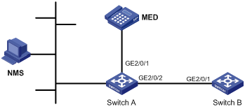
l The NMS and Switch A are located in the same Ethernet. An MED device and Switch B are connected to GigabitEthernet 2/0/1 and GigabitEthernet 2/0/2 of Switch A.
l Enable LLDP on the ports of Switch A and Switch B to monitor the link between Switch A and Switch B and the link between Switch A and the MED device on the NMS.
Network diagram
Figure 1-1 Network diagram for LLDP configuration
Configuration procedure
1) Configure Switch A.
# Enable LLDP globally.
<SwitchA> system-view
[SwitchA] lldp enable
# Enable LLDP on GigabitEthernet 2/0/1 and GigabitEthernet 2/0/2, setting the LLDP operating mode to Rx.
[SwitchA] interface gigabitethernet 2/0/1
[SwitchA-GigabitEthernet2/0/1] lldp enable
[SwitchA-GigabitEthernet2/0/1] lldp admin-status rx
[SwitchA-GigabitEthernet2/0/1] quit
[SwitchA] interface gigabitethernet2/0/2
[SwitchA-GigabitEthernet2/0/2] lldp enable
[SwitchA-GigabitEthernet2/0/2] lldp admin-status rx
[SwitchA-GigabitEthernet2/0/2] quit
2) Configure Switch B.
# Enable LLDP globally.
<SwitchB> system-view
[SwitchB] lldp enable
# Enable LLDP on GigabitEthernet2/0/1, setting the LLDP operating mode to Tx.
[SwitchB] interface gigabitethernet 2/0/1
[SwitchB-GigabitEthernet2/0/1] lldp enable
[SwitchB-GigabitEthernet2/0/1] lldp admin-status tx
[SwitchB-GigabitEthernet2/0/1] quit
3) Verify the configuration.
# Display the global LLDP status and port LLDP status on Switch A.
[SwitchA] display lldp status
Global status of LLDP : Enable
The current number of LLDP neighbors : 2
The current number of CDP neighbors : 0
LLDP neighbor information last changed time : 0 days, 0 hours, 4 minutes, 40 seconds
Transmit interval : 30s
Hold multiplier : 4
Reinit delay : 2s
Transmit delay : 2s
Trap interval : 5s
Fast start times : 3
Port 97 [GigabitEthernet2/0/1] :
Port status of LLDP : Enable
Admin status : Rx_Only
Trap flag : No
Roll time : 0s
Number of neighbors : 1
Number of MED neighbors : 1
Number of CDP neighbors : 0
Number of sent optional TLV : 0
Number of received unknown TLV : 0
Port 98 [GigabitEthernet2/0/2] :
Port status of LLDP : Enable
Admin status : Rx_Only
Trap flag : No
Roll time : 0s
Number of neighbors : 1
Number of MED neighbors : 0
Number of CDP neighbors : 0
Number of sent optional TLV : 0
Number of received unknown TLV : 3
# Tear down the link between Switch A and Switch B and then display the global LLDP status and port LLDP status on Switch A.
[SwitchA] display lldp status
Global status of LLDP : Enable
The current number of LLDP neighbors : 1
The current number of CDP neighbors : 0
LLDP neighbor information last changed time : 0 days, 0 hours, 5 minutes, 20 seconds
Transmit interval : 30s
Hold multiplier : 4
Reinit delay : 2s
Transmit delay : 2s
Trap interval : 5s
Fast start times : 3
Port 97 [GigabitEthernet2/0/1] :
Port status of LLDP : Enable
Admin status : Rx_Only
Trap flag : No
Roll time : 0s
Number of neighbors : 1
Number of MED neighbors : 1
Number of CDP neighbors : 0
Number of sent optional TLV : 0
Number of received unknown TLV : 5
Port 98 [GigabitEthernet2/0/2] :
Port status of LLDP : Enable
Admin status : Rx_Only
Trap flag : No
Roll time : 0s
Number of neighbors : 0
Number of MED neighbors : 0
Number of CDP neighbors : 0
Number of sent optional TLV : 0
Number of received unknown TLV : 0
CDP-Compatible LLDP Configuration Example
Network requirements
l GigabitEthernet 2/0/1 and GigabitEthernet 2/0/2 of Switch A are each connected to a Cisco IP phone.
l Configure voice VLAN 2 on Switch A. Enable CDP compatibility of LLDP on Switch A to allow the Cisco IP phones to automatically configure the voice VLAN, thus confining their voice traffic within the voice VLAN to be isolated from other types of traffic.
Network diagram
Figure 1-2 Network diagram for LLDP compatible with CDP configuration

Configuration procedure
1) Configure the voice VLAN on Switch A
# Create VLAN 2.
<SwitchA> system-view
[SwitchA] vlan 2
[SwitchA-vlan2] quit
# Enable the voice VLAN feature globally and configure VLAN 2 as the voice VLAN.
[SwitchA] voice vlan 2 enable
# Configure the link type of the ports to be trunk and enable the voice VLAN feature on GigabitEthernet 2/0/1 and GigabitEthernet 2/0/2.
[SwitchA] interface gigabitethernet 2/0/1
[SwitchA-GigabitEthernet2/0/1] port link-type trunk
[SwitchA-GigabitEthernet2/0/1] voice vlan enable
[SwitchA-GigabitEthernet2/0/1] quit
[SwitchA] interface gigabitethernet 2/0/2
[SwitchA-GigabitEthernet2/0/2] port link-type trunk
[SwitchA-GigabitEthernet2/0/2] voice vlan enable
[SwitchA-GigabitEthernet2/0/2] quit
2) Configure CDP-compatible LLDP on Switch A.
# Enable LLDP globally.
[SwitchA] lldp enable
# Enable LLDP to be compatible with CDP globally.
[SwitchA] lldp compliance cdp
# Enable LLDP, configure LLDP to operate in TxRx mode, and configure CDP-compatible LLDP to operate in TxRx mode on GigabitEthernet 2/0/1 and GigabitEthernet 2/0/2.
[SwitchA] interface gigabitethernet 2/0/1
[SwitchA-GigabitEthernet2/0/1] lldp enable
[SwitchA-GigabitEthernet2/0/1] lldp admin-status txrx
[SwitchA-GigabitEthernet2/0/1] lldp compliance admin-status cdp txrx
[SwitchA-GigabitEthernet2/0/1] quit
[SwitchA] interface gigabitethernet 2/0/2
[SwitchA-GigabitEthernet2/0/2] lldp enable
[SwitchA-GigabitEthernet2/0/2] lldp admin-status txrx
[SwitchA-GigabitEthernet2/0/2] lldp compliance admin-status cdp txrx
[SwitchA-GigabitEthernet2/0/2] quit
3) Verify the configuration
# Display the neighbor information on Switch A.
[SwitchA] display lldp neighbor-information
CDP neighbor-information of port 97[GigabitEthernet2/0/1]:
CDP neighbor index : 1
Chassis ID : SEP00141CBCDBFE
Port ID : Port 1
Sofrware version : P0030301MFG2
Platform : Cisco IP Phone 7960
Duplex : Full
CDP neighbor-information of port 98[GigabitEthernet2/0/2]:
CDP neighbor index : 2
Chassis ID : SEP00141CBCDBFF
Port ID : Port 1
Sofrware version : P0030301MFG2
Platform : Cisco IP Phone 7960
Duplex : Full
