- Table of Contents
-
- 02-WLAN
- 00-Preface
- 01-AP management configuration
- 02-Radio management configuration
- 03-WLAN access configuration
- 04-WLAN security configuration
- 05-WLAN authentication configuration
- 06-WIPS configuration
- 07-WLAN QoS configuration
- 08-WLAN roaming configuration
- 09-WLAN load balancing configuration
- 10-WLAN radio resource measurement configuration
- 11-Channel scanning configuration
- 12-Band navigation configuration
- 13-WLAN high availability configuration
- 14-802.11r configuration
- 15-Wireless location configuration
- 16-Hotspot 2.0 configuration
- 17-WLAN RRM configuration
- 18-WT configuration
- 19-IoT AP configuration
- 20-CM tunnel configuration
- 21-Cloud connection configuration
- 22-WLAN IP snooping configuration
- 23-WLAN fast forwarding configuration
- Related Documents
-
| Title | Size | Download |
|---|---|---|
| 13-WLAN high availability configuration | 205.12 KB |
Dual-link backup configuration task list
Associating an interface with a VSRP instance
Specifying a backup AC for an AP
Specifying a backup AC for an AP group
Configuring master CAPWAP tunnel preemption
Configuring master CAPWAP tunnel preemption for an AP
Configuring master CAPWAP tunnel preemption for an AP group
Configuring master CAPWAP tunnel preemption globally
Displaying and maintaining dual-link backup
Dual-link backup configuration example
Feature and hardware compatibility
Setting the number of active ACs
Setting the threshold and gap threshold for AP load balancing
Displaying and maintaining AP load balancing
AP load balancing configuration example
Configuring WLAN uplink detection
Associating a track entry with the WLAN uplink detection feature
WLAN uplink detection configuration example
Configuring dual-link backup
Overview
Dual-link backup uses VSRP to enable two ACs to form a VSRP group. An AP establishes a master tunnel and a backup CAPWAP tunnel with the master AC and the backup AC in the group, respectively. The two ACs establish a data backup channel between them for AP information backup. When the master AC fails, the backup AC becomes the master AC and takes over to avoid service interruption. When the failed master AC recovers, the master CAPWAP tunnel preemption feature determines the master CAPWAP tunnel based on the AP connection priority.
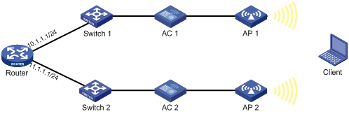
Figure 1 Network diagram for dual-link backup

Dual-link backup configuration task list
|
Tasks at a glance |
|
(Required.) Enabling dual-link backup |
|
(Required.) Associating an interface with a VSRP instance |
|
(Required.) Specifying a backup AC |
|
(Optional.) Configuring master CAPWAP tunnel preemption |
Configuration prerequisites
Before you configure dual-link backup, complete the following tasks:
· Configure a VSRP peer and VSRP instance. For more information, see High Availability Configuration Guide.
· Configure auto AP or manual APs on both ACs. The manual AP configuration must be identical on both ACs. For more information, see "Managing APs."
Enabling dual-link backup
|
Step |
Command |
Remarks |
|
1. Enter system view. |
system-view |
N/A |
|
2. Enable dual-link backup. |
wlan backup-mode dual-link |
By default, dual-link backup is disabled. Enable dual-link backup on both ACs. |
Associating an interface with a VSRP instance
|
Step |
Command |
Remarks |
|
1. Enter system view. |
system-view |
N/A |
|
2. Enter Layer 3 interface view or VLAN interface view. |
interface interface-type interface-number |
N/A |
|
3. Associate the interface with a VSRP instance. |
wlan vsrp-instance instance-name |
By default, no VSRP is associated with an interface. For two ACs to establish a data channel, associate the same VSRP instance with the interfaces on the ACs. The ACs back up only APs that come online on the associated interfaces. |
Specifying a backup AC
After an AP establishes a CAPWAP tunnel with the master AC, the AP will establish a backup CAPWAP tunnel with the specified backup AC.
As a best practice, set a higher AP connection priority for the master AC to ensure that APs can associate with the master AC first.
Specifying a backup AC for an AP
|
Step |
Command |
Remarks |
|
1. Enter system view. |
system-view |
N/A |
|
2. Enter AP view. |
N/A |
|
|
3. Set the AP connection priority. |
By default, an AP uses the configuration in AP group view. |
|
|
4. Specify a backup AC. |
By default, an AP uses the configuration in AP group view. |
Specifying a backup AC for an AP group
|
Step |
Command |
Remarks |
|
1. Enter system view. |
system-view |
N/A |
|
2. Enter AP group view. |
N/A |
|
|
3. Set the AP connection priority. |
priority priority |
By default, the AP connection priority is 4. |
|
4. Specify a backup AC. |
backup-ac { ip ipv4-address | ipv6 ipv6-address } |
By default, no backup AC is specified. |
Configuring master CAPWAP tunnel preemption
This feature enables a backup CAPWAP tunnel to become a master tunnel if the backup AC has higher AP connection priority than the master AC.
Configuring master CAPWAP tunnel preemption for an AP
|
Step |
Command |
Remarks |
|
1. Enter system view. |
system-view |
N/A |
|
1. Enter AP view. |
wlan ap ap-name [ model model-name ] |
N/A |
|
2. Configure master CAPWAP tunnel preemption. |
wlan tunnel-preempt { disable | enable } |
By default, an AP uses the configuration in AP group view. |
Configuring master CAPWAP tunnel preemption for an AP group
|
Step |
Command |
Remarks |
|
1. Enter system view. |
system-view |
N/A |
|
2. Enter AP group view. |
wlan ap-group groupname |
N/A |
|
3. Configure master CAPWAP tunnel preemption. |
wlan tunnel-preempt { disable | enable } |
By default, an AP uses the configuration in global configuration view. |
Configuring master CAPWAP tunnel preemption globally
|
Step |
Command |
Remarks |
|
1. Enter system view. |
system-view |
N/A |
|
2. Enter global configuration view. |
wlan global-configuration |
N/A |
|
3. Configure master CAPWAP tunnel preemption. |
wlan tunnel-preempt { disable | enable } |
By default, master CAPWAP tunnel preemption is disabled. |
Displaying and maintaining dual-link backup
Execute display commands in any view.
|
Task |
Command |
|
Display dual-link backup state information for all APs or the specified AP. |
display wlan ap backup dual-link { all | name ap-name } |
Dual-link backup configuration example
Network requirements
As shown in Figure 2, configure dual-link backup on AC 1 (master) and AC 2 (backup) to avoid service interruption when AC 1 fails. Configure the master CAPWAP tunnel preemption feature on AC 1, so that the AP reconnects to AC 1 when AC 1 recovers.
Configuration procedures
1. Configure AC 1:
# Create VLAN-interface 1 and assign an IP address to it.
<AC1> system-view
[AC1] interface vlan-interface 1
[AC1-Vlan-interface1] ip address 10.1.1.1 24
[AC1-Vlan-interface1] quit
# Create a VSRP peer named peer1.
[AC1] vsrp peer peer1
# Set the local IPv4 address to 10.1.1.1, and the peer IPv4 address to 10.1.1.2 for the IPv4 TCP control channel.
[AC1-vsrp-peer-peer1] peer 10.1.1.2 local 10.1.1.1
[AC1-vsrp-peer-peer1] quit
# Create a VSRP instance named instance1, set the ID of the VSRP instance to 10, and associate the VSRP instance with VSRP peer peer1.
[AC1] vsrp instance instance1
[AC1-vsrp-instance-instance1] backup id 10 peer peer1
[AC1-vsrp-instance-instance1] quit
# Associate VLAN-interface 1 with VSRP instance instance1.
[AC1] interface vlan-interface 1
[AC1-Vlan-interface1] wlan vsrp-instance instance1
[AC1-Vlan-interface1] quit
# Create an AP named ap1, and specify the AP model and serial ID. Set the AP connection priority to 7.
[AC1] wlan ap ap1 model WA4320i-ACN
[AC1-wlan-ap-ap1] serial-id 210235A1BSC123000050
[AC1-wlan-ap-ap1] priority 7
# Specify an IPv4 backup AC.
[AC1-wlan-ap-ap1] backup-ac ip 10.1.1.2
# Enable master CAPWAP tunnel preemption.
[AC1-wlan-ap-ap1] wlan tunnel-preempt enable
[AC1-wlan-ap-ap1] quit
# Enable dual-link backup.
[AC1] wlan backup-mode dual-link
2. Configure AC 2:
# Create VLAN-interface 1 and assign an IP address to it.
<AC2> system-view
[AC2] interface Vlan-interface 1
[AC2-Vlan-interface1] ip address 10.1.1.2 24
[AC2-Vlan-interface1] quit
# Create a VSRP peer named peer1.
[AC2] vsrp peer peer1
# Set the local IPv4 address to 10.1.1.2, and the peer IPv4 address to 10.1.1.1 for the IPv4 TCP control channel.
[AC2-vsrp-peer-peer1] peer 10.1.1.1 local 10.1.1.2
[AC2-vsrp-peer-peer1] quit
# Create a VSRP instance named instance1, set the ID of the VSRP instance to 10, and associate the VSRP instance with VSRP peer peer1.
[AC2] vsrp instance instance1
[AC2-vsrp-instance-instance1] backup id 10 peer peer1
[AC2-vsrp-instance-instance1] quit
# Associate VLAN-interface 1 with VSRP instance instance1.
[AC2] interface vlan-interface 1
[AC2-Vlan-interface1] wlan vsrp-instance instance1
[AC2-Vlan-interface1] quit
# Create an AP named ap1, and specify the AP model and serial ID. Set the AP connection priority to 5.
[AC2] wlan ap ap1 model WA4320i-ACN
[AC2-wlan-ap-ap1] serial-id 210235A1BSC123000050
[AC2-wlan-ap-ap1] priority 5
# Specify an IPv4 backup AC.
[AC2-wlan-ap-ap1] backup-ac ip 10.1.1.1
[AC2-wlan-ap-ap1] quit
# Enable dual-link backup.
[AC2] wlan backup-mode dual-link
Verifying the configuration
# Get the AP online on AC 1. (Details not shown.)
# Shut down VLAN-interface 1 on AC 1 and wait no longer than 3 minutes. (Details not shown.)
# Verify that the AP comes online on AC 2 and the AP state is R/M on AC 2. (Details not shown.)
# Bring up VLAN-interface 1 on AC 1. (Details not shown.)
# Verify that the AP comes online on AC 1 again and the AP state is R/M on AC 1. (Details not shown.)
Configuring AP load balancing
Overview
AP load balancing (LB) enables multiple ACs to form an IRF fabric to ensure centralized AP management and avoid wireless service interruption in case of AC failures.
AC roles
An AC has the following roles:
|
Role |
Description |
|
Master AC |
Master in an IRF fabric. A master AC performs the following tasks: · Manages the entire IRF fabric. · Load balances APs among active ACs according to an LB algorithm. · Maintains an AP LB table that records the CAPWAP tunnel establishment relationships between APs and active ACs, and synchronizes the table among all ACs in the fabric. |
|
Subordinate AC |
Subordinate in an IRF fabric. A subordinate AC processes services, forwards packets, and acts as a backup for the master AC. When the master AC fails, the system automatically elects a new master AC from the subordinate ACs in the IRF fabric. |
|
Active AC |
An AC that can establish CAPWAP tunnels with APs and load balance APs with other active ACs. The master AC is always an active AC. It selects a specific number of active ACs from the subordinate ACs. |
|
Non-active AC |
An AC that cannot establish CAPWAP tunnels with APs. Non-active ACs can only be subordinate ACs. When an active AC fails, a non-active AC will be elected as an active AC. |
|
Directly connected AC |
An AC that receives the first packet from an AP when the AP launches a CAPWAP tunnel establishment process. |
AP load balancing
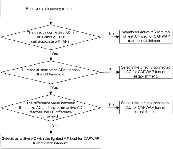
After multiple ACs form an IRF fabric, the IRF fabric appears as one AC to APs. When the IRF fabric receives a CAPWAP tunnel establishment request, the master AC uses an LB algorithm to select an AC from the active ACs for tunnel establishment. Figure 3 shows the LB algorithm.
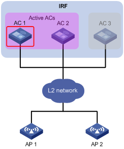
As shown in Figure 4, AC 1, AC 2, and AC 3 form an IRF fabric. AC 1 is the master AC and also an active AC. AC 2 is an active AC and also a directly connected AC to AP 1. AC 3 is a non-active AC. AP 1 establishes a CAPWAP tunnel with the IRF fabric by using the following process:
1. The AP sends a discovery request.
2. Upon receiving the discovery request, AC 2 notifies AC 1.
3. AC 1 determines whether a CAPWAP tunnel can be established with the AP, and then selects AC 1, for example, for CAPWAP tunnel establishment by using the LB algorithm.
4. AC 1 records the CAPWAP tunnel establishment relationship between the AP and AC 1 in the AP LB table and synchronizes the table to all ACs in the IRF fabric.
5. After receiving the AP LB table, AC 2 sends a discovery response to the AP.
6. After receiving the discovery response, the AP sends a join request to the IRF fabric.
7. The AC that receives the join request examines the AP LB table and learns that it is AC 1 that will establish a CAPWAP tunnel with the AP. Then, the AC forwards the join request to AC 1.
8. After receiving the join request, AC 1 sends a join response to the AP.
Figure 4 AP load balancing
Feature and hardware compatibility
|
Hardware series |
Model |
AP load balancing compatibility |
|
WX1800H series |
WX1804H WX1810H WX1820H |
No |
|
WX2500H series |
WX2510H WX2540H WX2560H |
No |
|
WX3000H series |
WX3010H WX3010H-L WX3010H-X WX3024H WX3024H-L |
No |
|
WX3500H series |
WX3508H WX3510H WX3520H WX3540H |
Yes |
|
WX5500E series |
WX5510E WX5540E |
Yes |
|
WX5500H series |
WX5540H WX5560H WX5580H |
Yes |
|
Access controller modules |
EWPXM1MAC0F EWPXM1WCME0 EWPXM2WCMD0F LSQM1WCMX20 LSQM1WCMX40 LSUM1WCME0 LSUM1WCMX20RT LSUM1WCMX40RT |
Yes |
Configuration prerequisites
Before configuring AP load balancing, set up an IRF fabric for the target ACs. For information about IRF, see Virtual Technologies Configuration Guide.
Setting the number of active ACs
After you set the number of active ACs, the master AC will select an active AC among the non-active ACs according to the order in which they are saved to the AC information table. An AC has higher priority if its information is saved earlier.
When an active AC fails, the master AC randomly selects a new active AC from non-active ACs.
To set the number of active ACs:
|
Step |
Command |
Remarks |
|
1. Enter system view. |
system-view |
N/A |
|
2. Set the number of active ACs. |
wlan ap-backup active count number |
By default, the number of active ACs is 1. Only the master AC can act as an active AC to establish CAPWAP tunnels with APs. |
Setting the threshold and gap threshold for AP load balancing
The threshold and gap threshold are used in the LB algorithm to implement AP load balancing among active ACs in an IRF fabric. For information about the LB algorithm, see "AP load balancing."
To set the threshold and gap threshold for AP load balancing:
|
Step |
Command |
Remarks |
|
1. Enter system view. |
system-view |
N/A |
|
2. Set the threshold and gap threshold for AP load balancing. |
wlan ap-backup load-balance threshold threshold-value gap gap-value |
The following default setting applies: · The AP load-balancing threshold is the maximum number of APs supported by the current AC. · The gap threshold is a quarter of APs associated with the directly connected AC. |
Displaying and maintaining AP load balancing
Execute display commands in any view.
|
Task |
Command |
|
Display AP LB status for all IRF member ACs. |
display wlan ap backup multislot |
AP load balancing configuration example
Network requirements
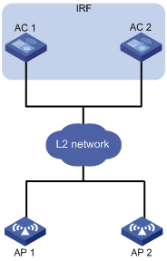
As shown in Figure 5, AC 1 and AC 2 form an IRF fabric. To implement central management of APs, configure both ACs as active ACs.
Configuration procedure
# Set up an IRF fabric. (Details not shown.)
For more information, see Virtual Technologies Configuration Guide.
# Set the number of active ACs to 2.
<AC> system-view
[AC] wlan ap-backup active count 2
Verifying the configuration
# Verify that both ACs can establish CAPWAP tunnels with APs and back up AP information for each other.
<AC> display wlan ap backup multislot
Borad Status
Total number of slots: 2
Slot ID State
1 active-only
2 active-only
Configuring WLAN uplink detection
Overview
When the uplink of an AC fails, clients cannot access external networks through the APs that are connected to the AC. WLAN uplink detection associates the uplink state of an AC with the radio state of the connected APs. When the uplink fails, the AC disables the radios of the APs. When the uplink recovers, the AC enables the radios of the APs. The association ensures that clients can associate with APs connected to another AC when the uplink of an AC fails.
This feature collaborates with a detection module and the Track module to function.
· When the track entry is in Positive state, the AC enables the radios of the connected APs.
· When the track entry is in Negative state, the AC disables the radios of the connected APs.
· When the track entry is in Invalid state, the AC does not change the radio state of the connected APs.
For more information about the track module, see High Availability Configuration Guide.
Associating a track entry with the WLAN uplink detection feature
|
Step |
Command |
Remarks |
|
1. Enter system view. |
system-view |
N/A |
|
2. Configure a detection module to detect the uplink state, and associate a track entry with the detection module. |
For information about Track association with detection modules, see High Availability Configuration Guide. |
N/A |
|
3. Associate the track entry with the WLAN uplink detection feature. |
wlan uplink track track-entry-number |
By default, WLAN uplink detection is not associated with any track entry. |
WLAN uplink detection configuration example
Network requirements
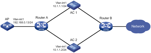
As shown in Figure 6, use an NQA operation to test the accessibility of each AC's uplink. Configure WLAN uplink detection on each AC, so that when the uplink of an AC fails, clients can associate with the AP connected to another AC that operates correctly.
Configuration procedure
1. Configure AC 1:
# Create an ICMP echo operation.
<AC1> system-view
[AC1] nqa entry admin test
[AC1-nqa-admin-test] type icmp-echo
# Specify 10.1.1.1 as the destination IP address of ICMP echo requests.
[AC1-nqa-admin-test-icmp-echo] destination ip 10.1.1.1
# Create reaction entry 1. If the number of consecutive probe failures reaches 5, collaboration is triggered.
[AC1-nqa-admin-test-icmp-echo] reaction 1 checked-element probe-fail threshold-type consecutive 5 action-type trigger-only
[AC1-nqa-admin-test-icmp-echo] quit
# Start the ICMP echo operation.
[AC1] nqa schedule admin test start-time now lifetime forever
# Configure track entry 1, and associate it with reaction entry 1 of the NQA operation (with administrator admin, and operation tag test).
[AC1] track 1 nqa entry admin test reaction 1
# Associate track entry 1 with WLAN uplink detection.
[AC1] wlan uplink track 1
[AC1] quit
2. Configure AC 2:
# Create an ICMP echo operation.
<AC2> system-view
[AC2] nqa entry admin test
[AC2-nqa-admin-test] type icmp-echo
# Specify 11.1.1.1 as the destination IP address of ICMP echo requests.
[AC2-nqa-admin-test-icmp-echo] destination ip 11.1.1.1
# Create reaction entry 1. If the number of consecutive probe failures reaches 5, collaboration is triggered.
[AC2-nqa-admin-test-icmp-echo] reaction 1 checked-element probe-fail threshold-type consecutive 5 action-type trigger-only
[AC2-nqa-admin-test-icmp-echo] quit
# Start the ICMP echo operation.
[AC2] nqa schedule admin test start-time now lifetime forever
# Configure track entry 1, and associate it with reaction entry 1 of the NQA operation (with administrator admin, and operation tag test).
[AC2] track 1 nqa entry admin test reaction 1
# Associate track entry 1 with WLAN uplink detection.
[AC2] wlan uplink track 1
[AC2] quit
Verifying the configuration
This example uses AC 1 to verify the configuration.
1. Verify that the radio of AP 1 is in Up state when the state of track entry 1 is Positive:
# Display information about track entry 1.
<AC1> display track 1
Track ID: 1
State: Positive
Duration: 0 days 1 hours 5 minutes 48 seconds
Notification delay: Positive 0, Negative 0 (in seconds)
Tracked object:
NQA entry: admin test
Reaction: 1
# Display detailed information about AP ap1.
<AC1> display wlan ap name ap1 verbose
AP name : ap1
AP ID : 1
AP group name : default-group
State : Run
Online time : 0 days 2 hours 25 minutes 12 seconds
System up time : 0 days 1 hours 22 minutes 12 seconds
Model : WA4320i-ACN
Region code : US
Region code lock : Disable
Serial ID : 210235A1BSC123000050
MAC address : 83D5-AB43-67FF
IP address : 1.1.1.2
H/W version : Ver.C
S/W version : V700R001B62D001
Boot version : 1.01
Description : wtp1
Priority : 4
Echo interval : 10 seconds
Statistics report interval : 50 seconds
Jumbo frame value : Disabled
MAC type : Local MAC & Split MAC
Tunnel mode : Local Bridging & 802.3 Frame & Native Frame
Discovery type : DHCP
Retransmission count : 3
Retransmission interval : 5 seconds
Firmware upgrade : Enabled
Sent control packets : 1
Received control packets : 1
Connection count : 1
Backup Ipv4 : Not configured
Backup Ipv6 : Not configured
Tunnel encryption : Disabled
LED mode : Normal
Radio 1:
Basic BSSID : N/A
Admin state : Up
Radio type : 802.11n(5GHz)
Antenna type : internal
Client dot11ac-only : Disabled
Client dot11n-only : Disabled
Channel band-width : 20/40MHz
Secondary channel offset : SCB
Short GI for 20MHz : Supported
Short GI for 40MHz : Supported
A-MSDU : Enabled
A-MPDU : Enabled
LDPC : Not Supported
STBC : Supported
Operational HT MCS Set:
Mandatory : Not configured
Supported : 0, 1, 2, 3, 4, 5, 6, 7, 8, 9,
10, 11, 12, 13, 14, 15
Multicast : Not configured
Channel : 64(auto)
Max power : 13 dBm
Operational rate:
Mandatory : 6, 12, 24 Mbps
Supported : 9, 18, 36, 48, 54 Mbps
Multicast : 24 Mbps
Disabled : Not configured
Distance : 1 km
ANI : Enabled
Fragmentation threshold : 2346 bytes
Beacon interval : 100 TU
Protection threshold : 2346 bytes
Long retry threshold : 4
Short retry threshold : 7
Maximum rx duration : 2000 ms
Noise Floor : 0 dBm
Smart antenna : Enabled
Smart antenna policy : Auto
Radio 2:
Basic BSSID : N/A
Admin state : Up
Radio type : 802.11b
Antenna type : internal
Channel : 5(auto)
Max power : 20 dBm
Preamble type : Short
Operational rate:
Mandatory : 1, 2 Mbps
Multicast : Auto
Supported : 5.5, 11 Mbps
Disabled : Not configured
Distance : 1 km
ANI : Enabled
Fragmentation threshold : 2346 bytes
Beacon interval : 100 TU
Protection threshold : 2346 bytes
Long retry threshold : 4
Short retry threshold : 7
Maximum rx duration : 2000 ms
Noise Floor : 0 dBm
2. Verify that the radio of AP 1 is in Down state when the state of track entry 1 is Negative:
# Display information about track entry 1.
<AC1> display track 1
Track ID: 1
State: Negative
Duration: 0 days 2 hours 5 minutes 48 seconds
Notification delay: Positive 0, Negative 0 (in seconds)
Tracked object:
NQA entry: admin test
Reaction: 1
# Display detailed information about AP ap1.
<AC1> display wlan ap name ap1 verbose
AP name : ap1
AP ID : 1
AP group name : default-group
State : Run
Online time : 0 days 3 hours 25 minutes 12 seconds
System up time : 0 days 2 hours 22 minutes 12 seconds
Model : WA4320i-ACN
Region code : US
Region code lock : Disable
Serial ID : 210235A1BSC123000050
MAC address : 83D5-AB43-67FF
IP address : 1.1.1.2
H/W version : Ver.C
S/W version : V700R001B62D001
Boot version : 1.01
Description : wtp1
Priority : 4
Echo interval : 10 seconds
Statistics report interval : 50 seconds
Jumbo frame value : Disabled
MAC type : Local MAC & Split MAC
Tunnel mode : Local Bridging & 802.3 Frame & Native Frame
Discovery type : DHCP
Retransmission count : 3
Retransmission interval : 5 seconds
Firmware upgrade : Enabled
Sent control packets : 1
Received control packets : 1
Connection count : 1
Backup Ipv4 : Not configured
Backup Ipv6 : Not configured
Tunnel encryption : Disabled
LED mode : Normal
Radio 1:
Basic BSSID : N/A
Admin state : Down
Radio type : 802.11n(5GHz)
Antenna type : internal
Client dot11ac-only : Disabled
Client dot11n-only : Disabled
Channel band-width : 20/40MHz
Secondary channel offset : SCB
Short GI for 20MHz : Supported
Short GI for 40MHz : Supported
A-MSDU : Enabled
A-MPDU : Enabled
LDPC : Not Supported
STBC : Supported
Operational HT MCS Set:
Mandatory : Not configured
Supported : 0, 1, 2, 3, 4, 5, 6, 7, 8, 9,
10, 11, 12, 13, 14, 15
Multicast : Not configured
Channel : 64(auto)
Max power : 13 dBm
Operational rate:
Mandatory : 6, 12, 24 Mbps
Supported : 9, 18, 36, 48, 54 Mbps
Multicast : 24 Mbps
Disabled : Not configured
Distance : 1 km
ANI : Enabled
Fragmentation threshold : 2346 bytes
Beacon interval : 100 TU
Protection threshold : 2346 bytes
Long retry threshold : 4
Short retry threshold : 7
Maximum rx duration : 2000 ms
Noise Floor : 0 dBm
Smart antenna : Enabled
Smart antenna policy : Auto
Radio 2:
Basic BSSID : N/A
Admin state : Down
Radio type : 802.11b
Antenna type : internal
Channel : 5(auto)
Max power : 20 dBm
Preamble type : Short
Operational rate:
Mandatory : 1, 2 Mbps
Multicast : Auto
Supported : 5.5, 11 Mbps
Disabled : Not configured
Distance : 1 km
ANI : Enabled
Fragmentation threshold : 2346 bytes
Beacon interval : 100 TU
Protection threshold : 2346 bytes
Long retry threshold : 4
Short retry threshold : 7
Maximum rx duration : 2000 ms
Noise Floor : 0 dBm
