- Table of Contents
-
- 02-WLAN
- 00-Preface
- 01-AP management configuration
- 02-Radio management configuration
- 03-WLAN access configuration
- 04-WLAN security configuration
- 05-WLAN authentication configuration
- 06-WIPS configuration
- 07-WLAN QoS configuration
- 08-WLAN roaming configuration
- 09-WLAN load balancing configuration
- 10-WLAN radio resource measurement configuration
- 11-Channel scanning configuration
- 12-Band navigation configuration
- 13-WLAN high availability configuration
- 14-802.11r configuration
- 15-Wireless location configuration
- 16-Hotspot 2.0 configuration
- 17-WLAN RRM configuration
- 18-WT configuration
- 19-IoT AP configuration
- 20-CM tunnel configuration
- 21-Cloud connection configuration
- 22-WLAN IP snooping configuration
- 23-WLAN fast forwarding configuration
- Related Documents
-
| Title | Size | Download |
|---|---|---|
| 10-WLAN radio resource measurement configuration | 99.22 KB |
Configuring WLAN radio resource measurement
Enabling radio resource measurement
Enabling radio resource measurement in radio view
Enabling radio resource measurement in AP group radio view
Setting the measurement duration and interval
Setting the measurement duration and interval in radio view
Setting the measurement duration and interval in AP group radio view
Setting the match mode for client radio resource measurement capabilities
Setting the match mode for client radio resource measurement capabilities in radio view··
Setting the match mode for client radio resource measurement capabilities in AP group radio view
Displaying and maintaining WLAN radio resource measurement
Radio resource measurement configuration examples
Configuring WLAN radio resource measurement
Overview
WLAN radio resource measurement measures channel qualities and radio performance. It enables client and APs to learn the wireless environment and use wireless resources such as spectrum, power, and bandwidth more effectively.
WLAN radio resource measurement includes 802.11h measurement and 802.11k measurement.
802.11h measurement
802.11h measurement measures channels in the 5 GHz band. Table 1 lists the measurement types it supports.
|
Type |
Description |
|
|
Spectrum management measurement |
Basic |
Measures whether a client has detected any of the following: · Packets from other BSSs. · OFDM preambles. · Radar signals. · Unknown signals. |
|
Clear Channel Assessment (CCA) |
Measures the percentage of busy time for a channel to the total measurement period. |
|
|
Receive Power Indication (RPI) |
Measures the percentage of time for different RPI ranges to the total measurement period. |
|
|
Transmit Power Control (TPC) measurement |
Measures the link redundancy and transmission power for clients. |
|
802.11h measurement operates in the following procedure:
1. An AP sets the Spectrum Mgmt field to 1 in beacons, probe responses, association responses, or reassociation responses to notify the clients that they can send 802.11h measurement requests.
2. Upon receiving a measurement request from a client, the AP performs the required measurement and sends a report to the client.
The AP can also send measurement requests periodically to clients and collect measurement reports from clients.
802.11k measurement
802.11k measurement measures channels in both the 2.4 GHz and 5 GHz bands. Table 2 lists the measurement types it supports.
|
Type |
Description |
|
|
Radio measurement |
Beacon |
Measures the Received Channel Power Indicator (RCPI) and Received Signal to Noise Indicator (RSNI) of beacons, measurement pilot packets, and probe responses. |
|
Frame |
Measures the number of frames transmitted and the average RCPI for these frames. |
|
|
Station statistics |
Measures the received and transmitted fragment counts, received and transmitted multicast frame counts, failed counts, retry counts, ACK failure counts. |
|
|
Transmit stream |
Measures the frame of a specific transmit stream. |
|
|
Channel load |
Measures the channel usage. |
|
|
Location |
Measures the relative locations of a requester and the requested. |
|
|
Noise histogram |
Measures the distribution of noise in different decibel ranges. |
|
|
Link measurement |
Measures RCPI, RSNI, and link redundancy for a requested link. |
|
|
Neighbor measurement |
Measures the channel and BSSID of neighbor APs. |
|
802.11k measurement operates in the following procedure:
1. An AP sets the Radio Measurement field to 1 in beacons, probe responses, association responses, or reassociation responses to notify the clients that they can send 802.11k measurement requests.
These frames also carry measurement capabilities of the AP to inform clients of measurement types that the AP supports.
The AP periodically sends Measurement Pilot frames to help clients fast discover the AP. Measurement Pilot frames are sent more frequently than beacons and carry less information.
2. Upon receiving a measurement request from a client, the AP performs the required measurement and sends a report to the client.
The AP can also send measurement requests periodically to clients and collect measurement reports from clients.
Configuration task list
|
Tasks at a glance |
|
(Required.) Enabling radio resource measurement |
|
(Optional.) Setting the measurement duration and interval |
|
(Optional.) Setting the match mode for client radio resource measurement capabilities |
Enabling radio resource measurement
Enabling radio resource measurement in radio view
|
Command |
Remarks |
|
|
1. Enter system view. |
system-view |
N/A |
|
2. Enter AP view. |
wlan ap ap-name [ model model-name ] |
N/A |
|
3. Enter radio view. |
radio radio-id |
N/A |
|
4. Enable radio resource measurement. |
resource-measure enable |
By default, the configuration in AP group view is used. You must enable radio resource measurement if you enable link, neighbor, or radio measurement. |
|
5. Enable spectrum management. |
spectrum-management enable |
By default, the configuration in AP group view is used. Spectrum or TPC measurement takes effect only after you enable spectrum management. For more information about this command, see WLAN Command Reference. |
|
6. Enable a measurement type. |
measure { all | link | neighbor | radio | spectrum | tpc } { enable | disable } |
By default, the configuration in AP group view is used. The spectrum and tpc keywords are available only on 5GHz radios. |
Enabling radio resource measurement in AP group radio view
|
Step |
Command |
Remarks |
|
1. Enter system view. |
system-view |
N/A |
|
2. Enter AP group view. |
wlan ap-group group-name |
N/A |
|
3. Enter AP model view. |
ap-model ap-model |
N/A |
|
4. Enter AP group radio view. |
radio radio-id |
N/A |
|
5. Enable radio resource measurement. |
resource-measure enable |
By default, radio resource measurement is disabled. You must enable radio resource measurement if you enable link, neighbor, or radio measurement. |
|
6. Enable spectrum management. |
spectrum-management enable |
By default, spectrum management is disabled. Spectrum or TPC measurement takes effect only after you enable spectrum management. For more information about this command, see WLAN Command Reference. |
|
7. Enable a measurement type. |
measure { all | link | neighbor | radio | spectrum | tpc } { enable | disable } |
By default, measurement is disabled. The spectrum and tpc keywords are available only on 5GHz radios. |
Setting the measurement duration and interval
When radio resource measurement is enabled for an AP, the AP sends measurement requests that carry the measurement duration to clients at the specified interval.
Setting the measurement duration and interval in radio view
|
Step |
Command |
Remarks |
|
1. Enter system view. |
system-view |
N/A |
|
2. Enter AP view. |
wlan ap ap-name [ model model-name ] |
N/A |
|
3. Enter radio view. |
radio radio-id |
N/A |
|
4. Set the measurement duration. |
measure-duration time |
By default, the configuration in AP group view is used. |
|
5. Set the measurement interval. |
measure-interval value |
By default, the configuration in AP group view is used. |
Setting the measurement duration and interval in AP group radio view
|
Step |
Command |
Remarks |
|
1. Enter system view. |
system-view |
N/A |
|
2. Enter AP group view. |
wlan ap-group group-name |
N/A |
|
3. Enter AP model view. |
ap-model ap-model |
N/A |
|
4. Enter AP group radio view. |
radio radio-id |
N/A |
|
5. Set the measurement duration. |
measure-duration time |
By default, the measurement duration is 500 TUs. |
|
6. Set the measurement interval. |
measure-interval value |
By default, the measurement interval is 30 seconds. |
Setting the match mode for client radio resource measurement capabilities
This feature allows a client to associate with an AP based on the predefined match criteria. Radio resource measurement capability refers to the radio resource measurement types supported by the AP and client. The device supports the following match modes for client radio resource measurement capabilities:
· All—A client is allowed to associate with an AP only when all its radio resource measurement capabilities match the AP's radio resource measurement capabilities.
· None—Client radio resource measurement capabilities are not checked.
· Partial—A client is allowed to associate with an AP as long as one of its radio resource measurement capabilities matches any of the AP's radio resource measurement capabilities.
Setting the match mode for client radio resource measurement capabilities in radio view
|
Step |
Command |
Remarks |
|
1. Enter system view. |
system-view |
N/A |
|
2. Enter AP view. |
wlan ap ap-name [ model model-name ] |
N/A |
|
3. Enter radio view. |
radio radio-id |
N/A |
|
4. Set the match mode for client radio resource measurement capabilities. |
rm-capability mode { all | none | partial } |
By default, the configuration in AP group view is used. |
Setting the match mode for client radio resource measurement capabilities in AP group radio view
|
Step |
Command |
Remarks |
|
1. Enter system view. |
system-view |
N/A |
|
2. Enter AP group view. |
wlan ap-group group-name |
N/A |
|
3. Enter AP model view. |
ap-model ap-model |
N/A |
|
4. Enter AP group radio view. |
radio radio-id |
N/A |
|
5. Set the match mode for client radio resource measurement capabilities. |
rm-capability mode { all | none | partial } |
By default, an AP does not check the radio resource measurement capabilities of a client. |
Displaying and maintaining WLAN radio resource measurement
Execute display commands in any view.
|
Task |
Command |
|
Display client measurement reports. |
display wlan measure-report ap ap-name radio radio-id [ client mac-address mac-address ] |
Radio resource measurement configuration examples
Network requirements
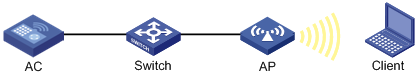
As shown in Figure 1, configure radio resource measurement to meet the following requirements:
· The client can come online only when all its radio resource measurement capabilities match the AP's.
· The client can perform all types of measurements.
Configuration procedures
# Create service template 1.
<AC> system-view
[AC] wlan service-template 1
# Set the SSID to resource-measure, and enable service template 1.
[AC-wlan-st-1] ssid resource-measure
[AC-wlan-st-1] service-template enable
[AC-wlan-st-1] quit
# Create the manual AP ap1, and specify the AP model and serial ID.
[AC] wlan ap ap1 model WA4320i-ACN
[AC-wlan-ap-ap1] serial-id 219801A0CNC138011454
# Enter radio view of radio 1.
[AC-wlan-ap-ap1] radio 1
# Enable spectrum management.
[AC-wlan-ap-ap1-radio-1] spectrum-management enable
# Enable radio resource measurement.
[AC-wlan-ap-ap1-radio-1] resource-measure enable
# Enable all measurement features.
[AC-wlan-ap-ap1-radio-1] measure all enable
# Set the match mode for client radio resource measurement capabilities to All.
[AC-wlan-ap-ap1-radio-1] rm-capability mode all
# Bind the service template to radio 1, and enable the radio.
[AC-wlan-ap-ap1-radio-1] service-template 1
[AC-wlan-ap-ap1-radio-1] radio enable
[AC-wlan-ap-ap1-radio-1] quit
[AC-wlan-ap-ap1] quit
Verifying the configuration
# Verify that the client has come online.
[AC] display wlan client
Total number of clients: 1
MAC address Username AP name RID IP address VLAN ID
00ee-bd44-557f N/A ap1 1 1.1.1.1 1
# Display measurement reports from the client.
[AC] display wlan measure-report ap ap1 radio 1
Total number of clients: 1
Client MAC address : 00ee-bd44-557f
Link measurement:
Link margin : 2 dBm
RCPI : -85 dBm
RSNI : 53 dBm
Noise histogram:
Antenna ID : 3
ANPI : -56 dBm
IPI0 to IPI10 density : 5 12 16 13 8 5 5 15 17 1 3
Spectrum measurement:
Transmit power : 20 dBm
BSS : Detected
OFDM preamble : Detected
Radar : Detected
Unidentified signal : Undetected
CCA busy fraction : 60
RPI0 to RPI7 density : 3 7 11 19 15 23 15 7
Frame report entry:
BSSID : a072-2351-e253
PHY type : fhss
Average RCPI : -10 dBm
Last RSNI : 2 dBm
Last RCPI : -20 dBm
Frames : 1
Dot11BSSAverageAccessDelay group:
Average access delay : 32 ms
BestEffort average access delay : 1 ms
Background average access delay : 1 ms
Video average access delay : 1 ms
Voice average access delay : 1 ms
Clients : 32
Channel utilization rate : 11
Transmit stream:
Traffic ID : 0
Sent MSDUs : 60
Discarded MSDUs : 5
Failed MSDUs : 3
MSDUs resent multiple times : 3
Lost QoS CF-Polls : 2
Average queue delay : 2 ms
Average transmit delay : 1 ms
Bin0 range : 0 to 10 ms
Bin0 to Bin5 : 5 10 10 5 10 10
