- Table of Contents
-
- 05-Web configuration examples (AC+fit AP)
- 01-Telnet Access Control Configuration Example
- 02-IPv6 Telnet Access Control Configuration Example
- 03-Web Access Control Configuration Example
- 04-User Role Assignment for Local Web Authentication Users Configuration Example
- 05-SSH Local Authentication Configuration Example
- 06-SSH User Remote Password Authentication Configuration Example
- 07-IPv6 SSH User Remote Password Authentication Configuration Example
- 08-Password Control Configuration Example
- 09-Licensing Configuration Example
- 10-Automatic License Installation Configuration Example
- 11-Layer 2 Static Link Aggregation Configuration Example
- 12-Layer 2 Dynamic Link Aggregation Configuration Example
- 13-PPPoE Client Configuration Example
- 14-Static IPv6 Address Configuration Example
- 15-IPv6 Static Routing Configuration Example
- 16-Static IPv4 DNS Configuration Example
- 17-Static IPv6 DNS Configuration Example
- 18-IGMP Snooping Configuration Example
- 19-MLD Snooping Configuration Example
- 20-IPv4 DNS Proxy Configuration Example
- 21-IPv6 DNS Proxy Configuration Example
- 22-Static NAT Configuration Example
- 23-Dynamic NAT Configuration Example
- 24-IPv4 ACL-Based Packet Filter Configuration Example
- 25-IPv6 ACL-Based Packet Filter Configuration Example
- 26-ARP Attack Protection Configuration Example
- 27-ARP Proxy Configuration Example
- 28-Dynamic IPv4 DNS Configuration Example
- 29-Dynamic IPv6 DNS Configuration Example
- 30-WLAN Access Configuration Example
- 31-Different Wireless Services on Different Radios Configuration Example
- 32-CAPWAP Tunnel Establishment Through DHCP Configuration Example
- 33-CAPWAP Tunnel Establishment Through DHCPv6 Configuration Example
- 34-CAPWAP Tunnel Establishment Through DNS Configuration Example
- 35-CAPWAP Tunnel Establishment Through DNSv6 Configuration Example
- 36-Auto AP Configuration Example
- 37-AP Group Configuration Example
- 38-Radio Management Configuration Example
- 39-Load Balancing Group-Based Session-Mode Load Balancing Configuration Example
- 40-Radio-Based Session-Mode Load Balancing Configuration Example
- 41-A-MPDU and A-MSDU Configuration Example
- 42-Device Classification and Countermeasure Configuration Example
- 43-Malformed Packet Detection and Flood Attack Detection Configuration Example
- 44-Signature-Based Attack Detection Configuration Example
- 45-802.1X RADIUS-Based AAA Configuration Example
- 46-VLAN Interface-Based Direct Portal Authentication Configuration Example
- 47-Service Template-Based Direct Portal Authentication Configuration Example
- 48-Wireless Spectrum Analysis Configuration Example
- 49-Auto DFS Configuration Examples
- 50-Auto TPC Configuration Examples
- 51-Whitelist-Based Client Access Control Configuration Example
- 52-Blacklist-Based Client Access Control Configuration Example
- 53-CAC Configuration Example
- 54-WLAN Probe Configuration Example
- 55-Intra-AC Roaming Configuration Example
- 56-Bonjour Gateway Configuration Example
- 57-IPv4 Multicast Optimization Configuration Examples
- 58-IPv6 Multicast Optimization Configuration Examples
- 59-Ping Configuration Example
- 60-Local Packet Capture Configuration Example
- 61-Remote Packet Capture Configuration Example
- Related Documents
-
| Title | Size | Download |
|---|---|---|
| 46-VLAN Interface-Based Direct Portal Authentication Configuration Example | 1.04 MB |
|
|
|
H3C Access Controllers |
|
Comware 7 VLAN Interface-Based Direct Portal Authentication |
|
Configuration Example |
Copyright © 2022 New H3C Technologies Co., Ltd. All rights reserved.
No part of this manual may be reproduced or transmitted in any form or by any means without prior written consent of New H3C Technologies Co., Ltd.
Except for the trademarks of New H3C Technologies Co., Ltd., any trademarks that may be mentioned in this document are the property of their respective owners.
The information in this document is subject to change without notice.
Overview
The following information provides an example for configuring VLAN interface-based direct portal authentication.
Prerequisites
The following information applies to Comware 7-based access controllers. Procedures and information in the examples might be slightly different depending on the software or hardware version of the H3C access controllers.
The configuration examples were created and verified in a lab environment, and all the devices were started with the factory default configuration. When you are working on a live network, make sure you understand the potential impact of every command on your network.
The following information is provided based on the assumption that you have basic knowledge of portal authentication.
Example: Configuring VLAN interface-based direct portal authentication
The configuration procedure for IPv4 and IPv6 direct portal authentication are the same. This example uses IPv4 direct portal authentication.
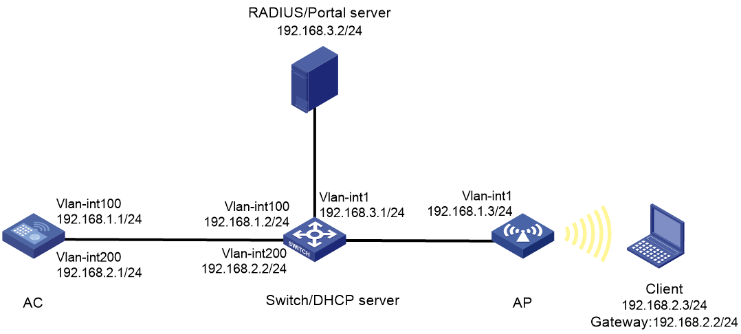
Network configuration
As shown in Figure 1, the switch acts as a DHCP server to assign IPv4 addresses to the AP and the wireless client. A portal server acts as both a portal authentication server and a portal Web server. A RADIUS server acts as the authentication and accounting server.
Configure the AC to perform direct portal authentication on the client and configure server detection on the AC to meet the following requirements:
· Detect the reachability state of the portal authentication server.
· Send log messages upon detecting server state changes.
· Disable portal authentication when the authentication server is unreachable.
Procedures
Configuring the AC
Configuring IP addresses
# Configure an IP address to each interface and make sure the client, the servers, and the AC can reach each other. (Details not shown.)
Configuring a RADIUS scheme
1. Click the Network View tab at the bottom of the page.
2. From the navigation pane, select Network Security > Authentication.
3. Click the RADIUS tab.
4. Click the Add button
![]() to
create a RADIUS scheme.
to
create a RADIUS scheme.
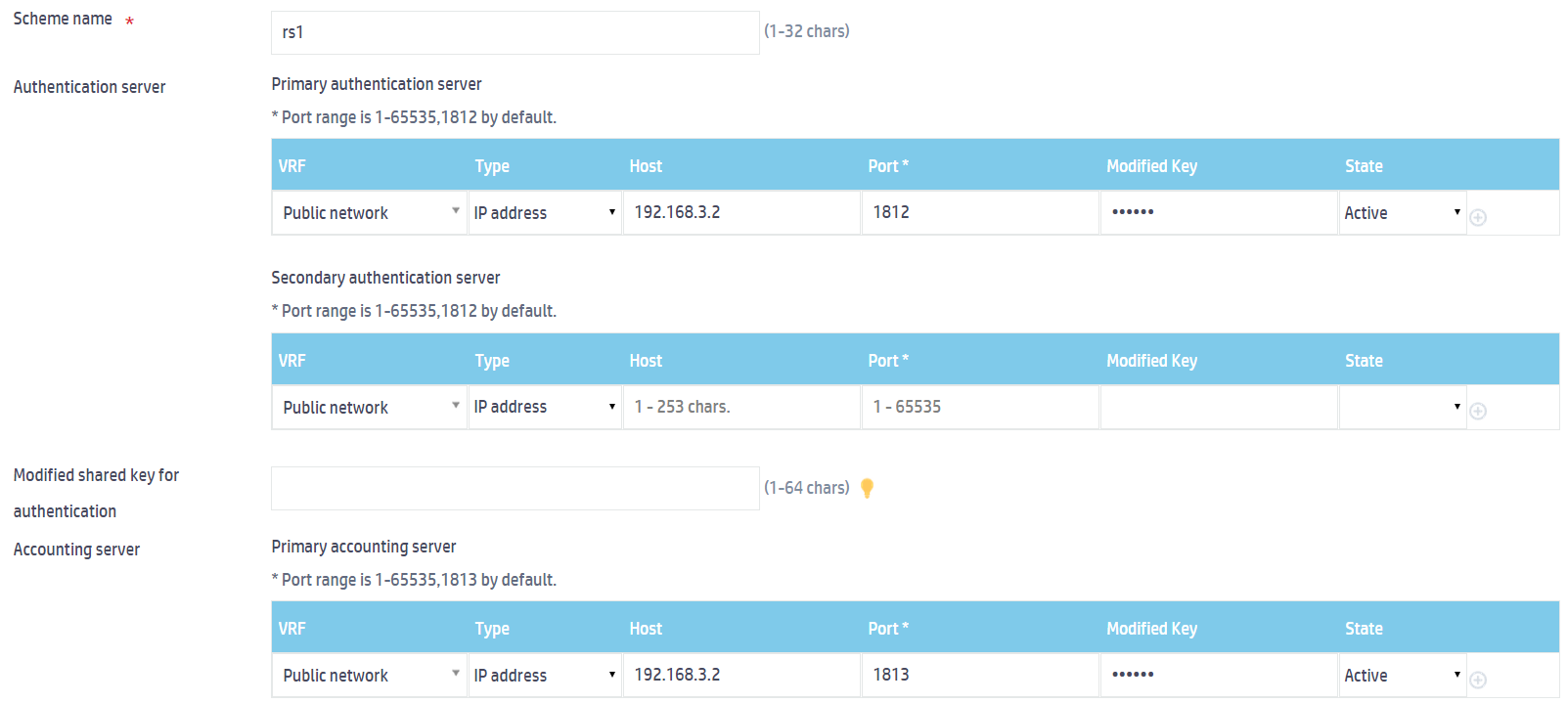
a. Enter the scheme name rs1.
b. Configure the primary authentication server:
- Select IP address from the Type field.
- Enter 192.168.3.2 in the Host field.
- Enter 1812 in the Port field.
- Enter radius in the Modified Key field as the shared key.
- Select Active from the State field.
c. Configure the primary accounting server:
- Select IP address from the Type field.
- Enter 192.168.3.2 in the Host field.
- Enter 1813 in the Port field.
- Enter radius in the Modified Key field.
- Select Active from the State field.
Figure 2 Configuring a RADIUS scheme
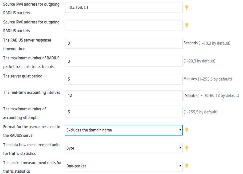
5. Click Show advanced settings to configure the advanced settings for the RADIUS scheme.
a. Specify 192.168.1.1 as the source IPv4 address for outgoing RADIUS packets.
b. Select Excludes the domain name from the Format for the usernames sent to the RADIUS server field.
c. Use the default settings for the other parameters.
Figure 3 Configuring advanced settings
6. Click Apply.
Configuring an ISP domain
1. From the navigation pane, select Network Security > Authentication.
2. Click the ISP Domains tab.
3. Click the Add button ![]() to create an ISP domain.
to create an ISP domain.
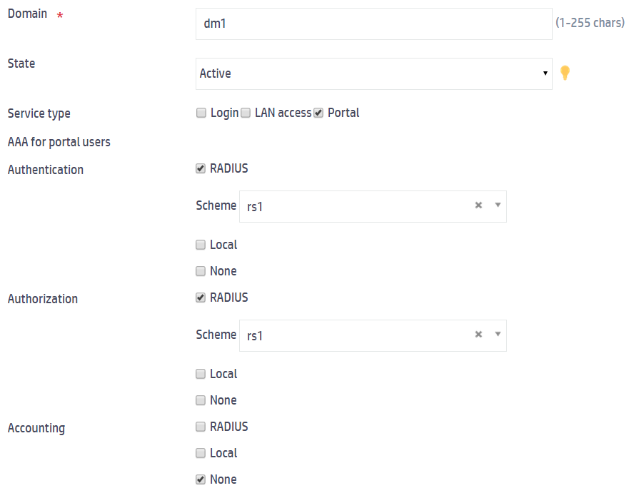
a. Enter the domain name dm1.
b. Set the state to Active.
c. Select Portal from the Service type field.
d. Select RADIUS for authentication and authorization, specify RADIUS scheme rs1 as the authentication and authorization scheme, and select None for accounting.
e. Click Apply.
Figure 4 Configuring an ISP domain
Configuring portal authentication
1. From the navigation pane, select Network Security > Access Control.
2. Click the Portal tab.
3. Click the right chevron button in the Portal authentication server row and then click the Add button ![]() to
create a portal authentication server.
to
create a portal authentication server.
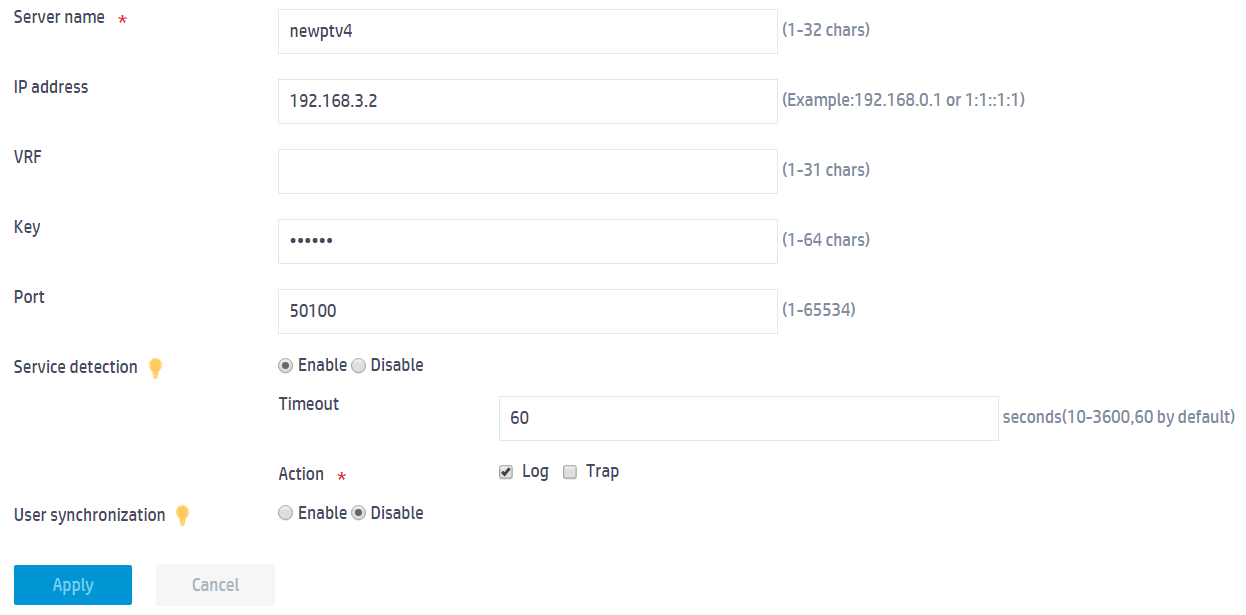
a. Enter the server name newptv4.
b. Enter the IP address of the portal authentication server.
c. Set the plaintext key to 123456.
d. Configure the portal authentication server detection feature:
- Enable portal authentication server detection.
- Set the detection timeout time to 60 seconds. The timeout time must be equal to or greater than the server heartbeat interval.
- Set the action to take upon detecting a server status change to sending logs.
e. Use the default setting for the other parameters.
f. Click Apply.
Figure 5 Configuring a portal authentication server
4. Click the right chevron button in the Portal Web server row and then click the Add button ![]() to
create a portal Web server.
to
create a portal Web server.
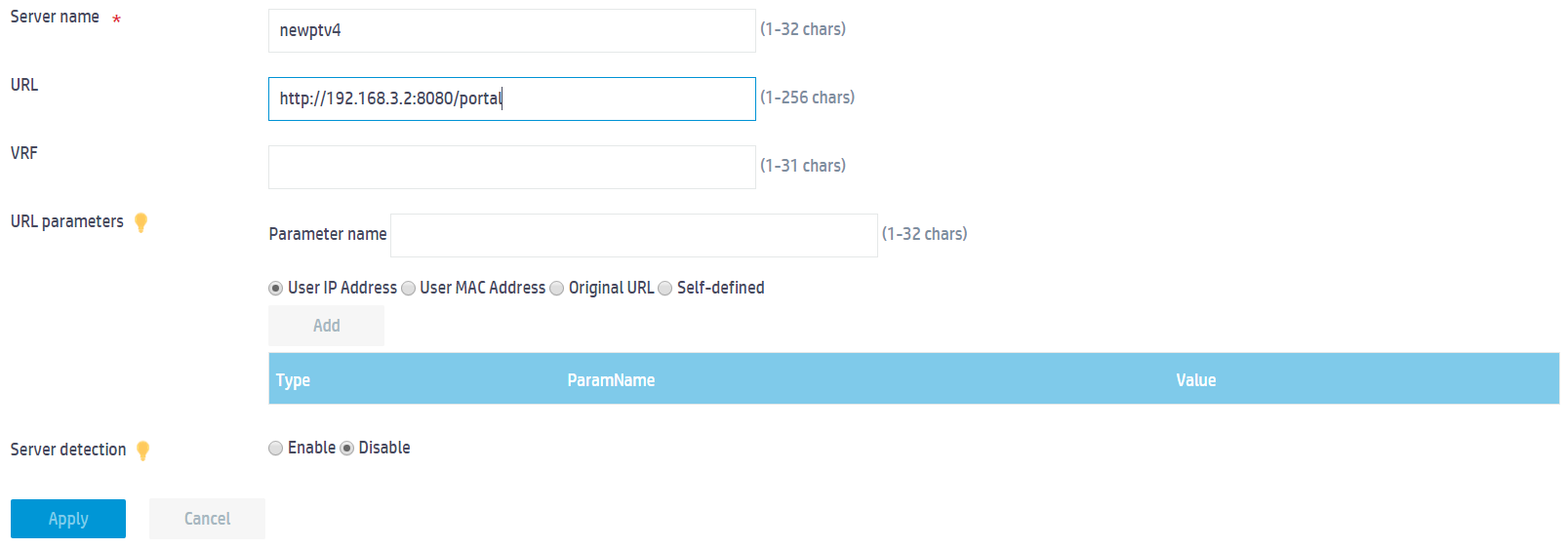
a. Enter the server name newptv4.
b. Enter the URL http://192.168.3.2:8080/portal.
c. Use the default setting for the other parameters.
d. Click Apply.
Figure 2 Configuring a portal Web server
5. Click the right chevron
button in the Interface policy row and then click
the Add ![]() to create an interface policy.
to create an interface policy.
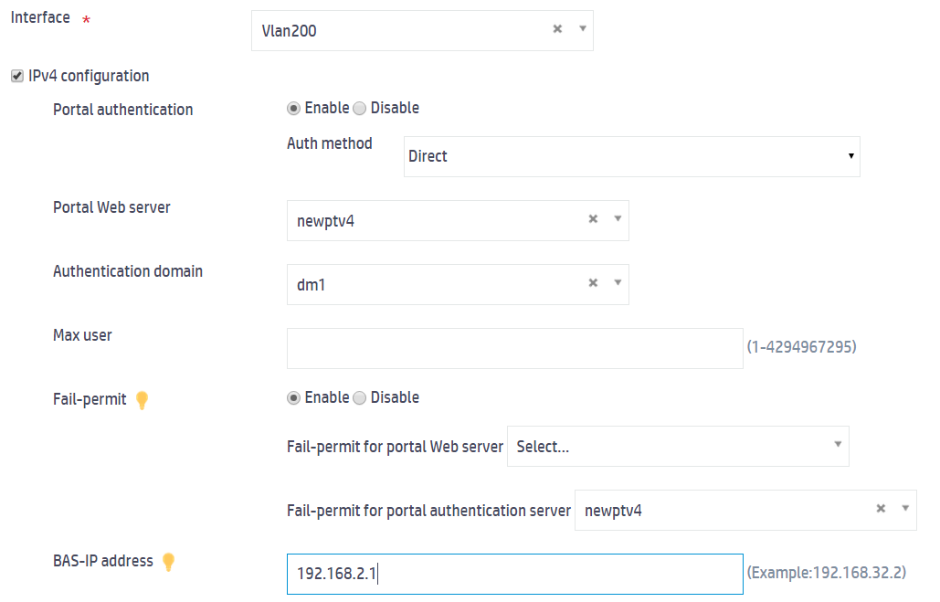
a. Select VLAN-interface 200.
b. Select IPv4 configuration and configure the parameters as follows:
- Enable portal authentication and specify the direct authentication method.
- Specify newptv4 as the portal Web server.
- Specify ISP domain dm1 as the authentication domain.
- Enable the fail-permit feature.
- Specify 192.168.2.1 as the BAS-IP address.
- Use the default settings for the other parameters.
c. Click Apply.
Figure 6 Configuring an interface policy
6. Click the right chevron
button in the Portal-free rule row and then click the Add button ![]() to create a portal-free rule.
to create a portal-free rule.
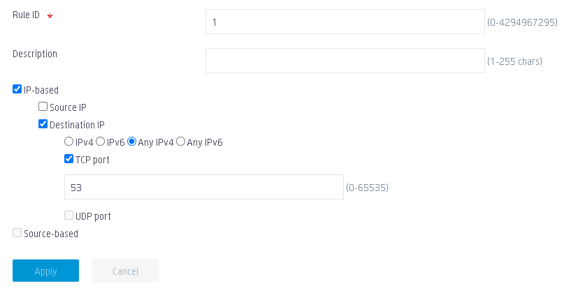
a. Set the rule ID to 1.
b. Select IP-based.
c. Select Destination IP.
d. Select Any IPv4.
e. Select TCP port, and set the port number to 53.
f. Use the default settings for the other parameters.
g. Click Apply.
Figure 7 Configuring portal-free rule 1
7. Click the right chevron
button in the Portal-free rule row and then click the Add button ![]() to create a portal-free rule.
to create a portal-free rule.
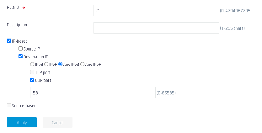
a. Set the rule ID to 2.
b. Select IP-based.
c. Select Destination IP.
d. Select Any IPv4.
e. Select UDP port, and set the port number to 53.
f. Use the default settings for the other parameters.
g. Click Apply.
Figure 8 Configuring portal-free rule 2
8. Click the right chevron
button in the Portal-free rule row and then click the Add button ![]() to create a portal-free rule.
to create a portal-free rule.
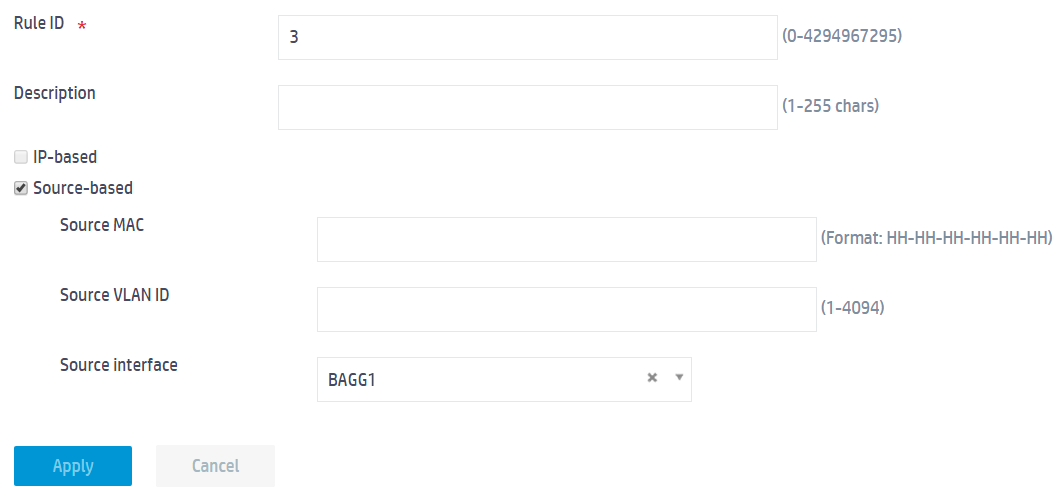
a. Set the rule ID to 3.
b. Select Source-based.
c. Select BAGG1 from the Source interface field.
d. Use the default settings for the other parameters.
e. Click Apply.
Figure 9 Configuring portal-free rule 3
Configuring the WLAN service
1. From the navigation pane, select Wireless Configuration > Wireless Networks.
2. Click the Add button ![]() to create a service template.
to create a service template.
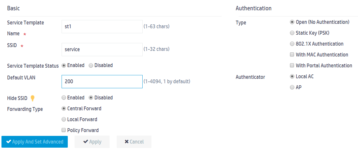
a. In the Basic area, set the service template name to st1, set the SSID to service, enable the service template, and set the default VLAN to 200.
b. Use the default settings for the other parameters.
c. Click Apply.
Figure 10 Configuring a wireless network
Creating an AP and binding service template st1 to the AP
Details not shown.
Configuring the switch
Details not shown.
Configuring the RADIUS server
In this example, the RADIUS server runs IMC PLAT 7.1(E0303) and IMC UAM 7.1(E0304).
Adding the AC to IMC as an access device
1. Log in to IMC and click the User tab.
2. From the navigation tree, select User Access Policy > Access Device Management > Access Device.
3. Click Add.
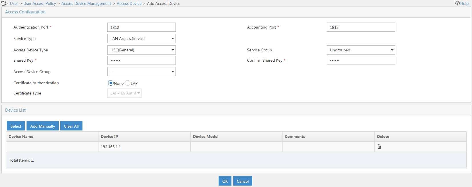
The Add Access Device page opens.
4. In the Access Configuration area, set the shared key to radius. The shared key must be the same as that set in the RADIUS configuration on the AC.
5. In the Device List area, click the Add Manually button to add an access device.
6. On the Add Access Device Manually page, enter 192.168.1.1 in the Start IP field and click Apply.
7. Use the default settings for the other parameters.
8. Click OK.
Figure 11 Adding an access device
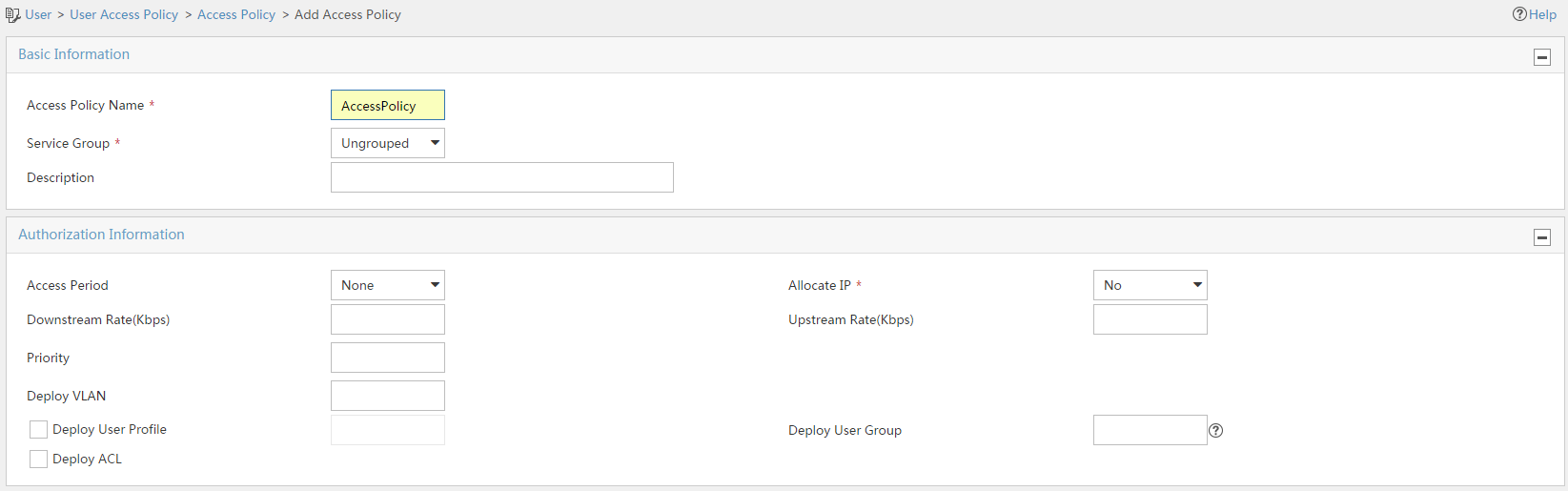
Adding an access policy
1. Click the User tab.
2. From the navigation tree, select User Access Policy > Access Policy.
3. Click Add.
4. On the Add Access Policy page, configure the following parameters:
a. Enter AccessPolicy in the Access Policy Name field.
b. Select Ungrouped from the Service Group field.
c. Use the default settings for the other parameters.
Figure 12 Adding an access policy
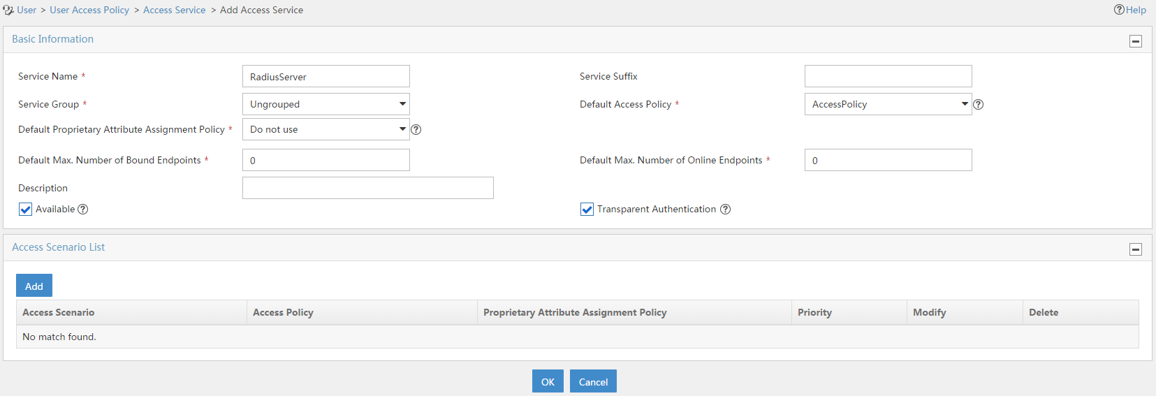
Adding an access service
1. Click the User tab.
2. From the navigation tree, select User Access Policy > Access Service.
3. Click Add.
4. On the Add Access Service page, configure the following parameters:
a. Enter service name RadiusServer.
b. Specify AccessPolicy as the default access policy.
c. Use the default settings for the other parameters.
Figure 13 Adding an access service
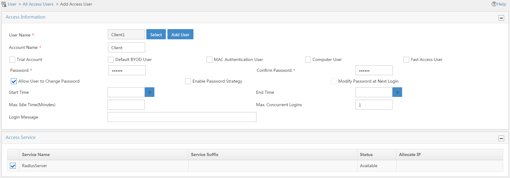
Adding an access user
1. Click the User tab.
2. From the navigation tree, select Access User > All Access Users.
The access user list opens.
3. Click Add.
The Add Access User page opens.
4. In the Access Information area, configure the following parameters:
a. Click Select to select an existing user or click Add User to add a new user.
b. Enter the account name in the Account Name field.
c. Enter the user password in the Password and Confirm Password fields.
5. In the Access Service area, select RadiusServer from the list.
6. Click OK.
Figure 14 Adding an access user
Configuring the portal server
In this example, the RADIUS server runs IMC PLAT 7.1(E0303) and IMC UAM 7.1(E0304).
Configuring a portal authentication server
1. Log in to IMC and click the User tab.
2. From the navigation tree, select Access Service > Portal Service Management > Server.
3. On the portal authentication server configuration page, configure the portal server parameters as needed.
This example uses the default settings.
Figure 15 Configuring the portal authentication server
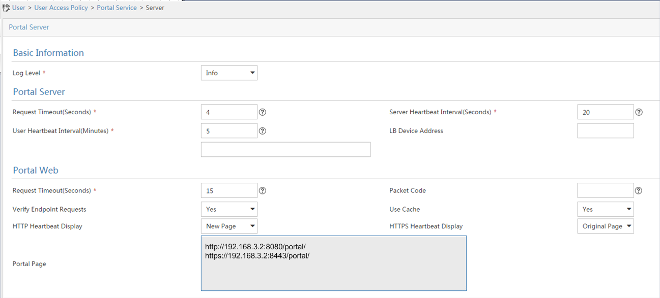
4. Click OK.
Configuring an IP address group
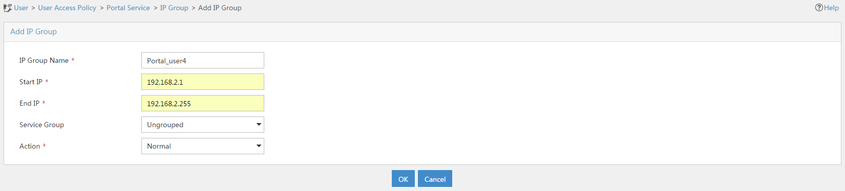
1. From the navigation pane, select User Access Policy > Portal Service > IP Group.
2. Click Add.
3. On the Add IP Group page, configure the following parameters:
a. Enter the IP group name.
b. Enter the start IP address and end IP address of the IP group. Make sure the client's IP address is in the IP group.
c. Select a service group.
This example uses the default group Ungrouped.
d. Click OK.
Figure 8 Adding an IP address group
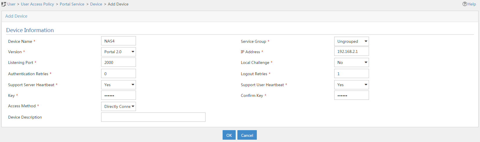
Adding a portal device
1. From the navigation tree, select User Access Policy > Portal Service > Device.
2. Click Add.
3. On the Add Device page, configure the following parameters:
a. Enter the device name.
b. Select portal version 2.
c. Enter the IP address of the AC's interface connected to the client.
d. Set the AC to support the portal server heartbeat and user heartbeat functions.
e. Enter the key, which must be the same as that configured on the AC.
f. Specify Directly Connected as the access method.
g. Use the default settings for the other parameters.
h. Click OK.
Figure 9 Adding a portal device
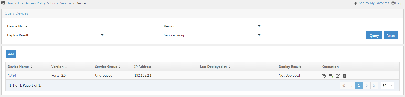
Associating the portal device with the IP address group
1. Click the Port Group icon ![]() in the Operation column of device NAS4.
in the Operation column of device NAS4.
Figure 16 Device list
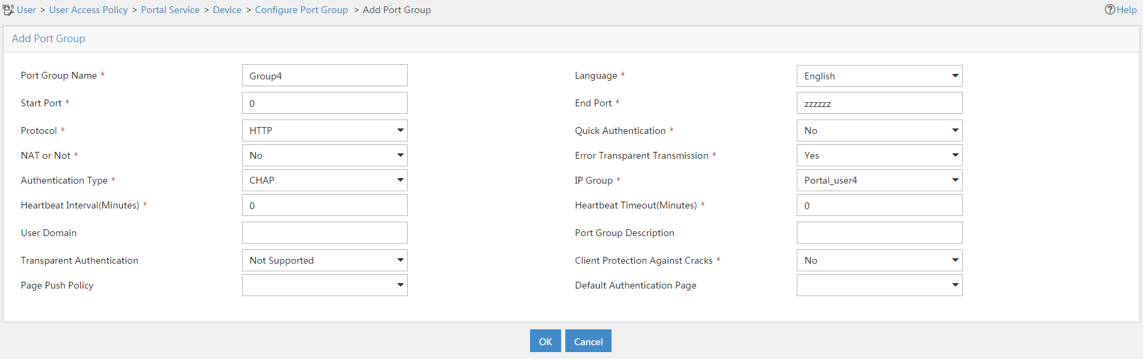
2. Click Add.
3. On the Add Port Group page, configure the following parameters:
a. Enter the port group name.
b. Select the configured IP address group. The IP address used by the user to access the network must be within this IP address group.
c. Use the default settings for the other parameters.
d. Click OK.
Figure 17 Adding a port group
Committing the configuration changes
# From the navigation tree, select Access Service > Service Parameters > Validate System Configuration to make the configurations take effect.
Verifying the configuration
# On the client, use the configured user account to perform portal authentication through a Web browser. Before passing the authentication, the user can access only the authentication page http://192.168.3.2:8080/portal. All Web requests from the user will be redirected to the authentication page. After passing the authentication, the user can access other network resources.
# After the user passes portal authentication, verify that the user has come online on the AC.
1. Click the Network View tab at the bottom of the page.
2. From the navigation pane, select Network Security > Access Control.
3. Click the Portal tab.
4. Click the right chevron button in the Online users row.
The information about the user is displayed in the online user list.
Related documentation
H3C Access Controllers Web-Based Configuration Guide
