- Table of Contents
-
- 05-Web configuration examples (AC+fit AP)
- 01-Telnet Access Control Configuration Example
- 02-IPv6 Telnet Access Control Configuration Example
- 03-Web Access Control Configuration Example
- 04-User Role Assignment for Local Web Authentication Users Configuration Example
- 05-SSH Local Authentication Configuration Example
- 06-SSH User Remote Password Authentication Configuration Example
- 07-IPv6 SSH User Remote Password Authentication Configuration Example
- 08-Password Control Configuration Example
- 09-Licensing Configuration Example
- 10-Automatic License Installation Configuration Example
- 11-Layer 2 Static Link Aggregation Configuration Example
- 12-Layer 2 Dynamic Link Aggregation Configuration Example
- 13-PPPoE Client Configuration Example
- 14-Static IPv6 Address Configuration Example
- 15-IPv6 Static Routing Configuration Example
- 16-Static IPv4 DNS Configuration Example
- 17-Static IPv6 DNS Configuration Example
- 18-IGMP Snooping Configuration Example
- 19-MLD Snooping Configuration Example
- 20-IPv4 DNS Proxy Configuration Example
- 21-IPv6 DNS Proxy Configuration Example
- 22-Static NAT Configuration Example
- 23-Dynamic NAT Configuration Example
- 24-IPv4 ACL-Based Packet Filter Configuration Example
- 25-IPv6 ACL-Based Packet Filter Configuration Example
- 26-ARP Attack Protection Configuration Example
- 27-ARP Proxy Configuration Example
- 28-Dynamic IPv4 DNS Configuration Example
- 29-Dynamic IPv6 DNS Configuration Example
- 30-WLAN Access Configuration Example
- 31-Different Wireless Services on Different Radios Configuration Example
- 32-CAPWAP Tunnel Establishment Through DHCP Configuration Example
- 33-CAPWAP Tunnel Establishment Through DHCPv6 Configuration Example
- 34-CAPWAP Tunnel Establishment Through DNS Configuration Example
- 35-CAPWAP Tunnel Establishment Through DNSv6 Configuration Example
- 36-Auto AP Configuration Example
- 37-AP Group Configuration Example
- 38-Radio Management Configuration Example
- 39-Load Balancing Group-Based Session-Mode Load Balancing Configuration Example
- 40-Radio-Based Session-Mode Load Balancing Configuration Example
- 41-A-MPDU and A-MSDU Configuration Example
- 42-Device Classification and Countermeasure Configuration Example
- 43-Malformed Packet Detection and Flood Attack Detection Configuration Example
- 44-Signature-Based Attack Detection Configuration Example
- 45-802.1X RADIUS-Based AAA Configuration Example
- 46-VLAN Interface-Based Direct Portal Authentication Configuration Example
- 47-Service Template-Based Direct Portal Authentication Configuration Example
- 48-Wireless Spectrum Analysis Configuration Example
- 49-Auto DFS Configuration Examples
- 50-Auto TPC Configuration Examples
- 51-Whitelist-Based Client Access Control Configuration Example
- 52-Blacklist-Based Client Access Control Configuration Example
- 53-CAC Configuration Example
- 54-WLAN Probe Configuration Example
- 55-Intra-AC Roaming Configuration Example
- 56-Bonjour Gateway Configuration Example
- 57-IPv4 Multicast Optimization Configuration Examples
- 58-IPv6 Multicast Optimization Configuration Examples
- 59-Ping Configuration Example
- 60-Local Packet Capture Configuration Example
- 61-Remote Packet Capture Configuration Example
- Related Documents
-
| Title | Size | Download |
|---|---|---|
| 31-Different Wireless Services on Different Radios Configuration Example | 410.49 KB |
|
|
|
H3C Access Controllers |
|
Comware 7 Different Wireless Services on Different Radios |
|
Configuration Examples |
Copyright © 2022 New H3C Technologies Co., Ltd. All rights reserved.
No part of this manual may be reproduced or transmitted in any form or by any means without prior written consent of New H3C Technologies Co., Ltd.
Except for the trademarks of New H3C Technologies Co., Ltd., any trademarks that may be mentioned in this document are the property of their respective owners.
The information in this document is subject to change without notice.
Contents
Example: Configuring different wireless services on different radios
Configuring the Layer 3 switch
Overview
The following information provides an example for binding wireless services with different SSIDs to radios at different frequency bands.
Prerequisites
The following information applies to Comware 7-based access controllers. Procedures and information in the examples might be slightly different depending on the software or hardware version of the H3C access controllers.
The configuration examples were created and verified in a lab environment, and all the devices were started with the factory default configuration. When you are working on a live network, make sure you understand the potential impact of every command on your network.
Example: Configuring different wireless services on different radios
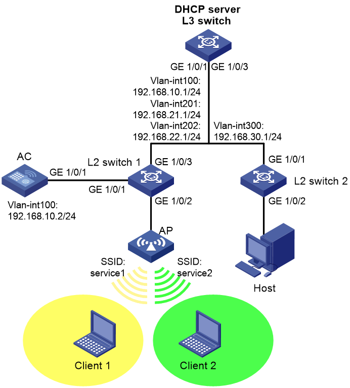
Network configuration
As shown in Figure 1, in centralized forwarding, the AC is attached to Layer 2 switch 1 in hair-pin mode. The Layer 3 switch acts as the DHCP server to assign IP addresses to the AP and the clients. Configure wireless network settings for the clients to associate with the AC through the AP and visit the host.
· Configure Client 1 to access the WLAN with SSID service1 through VLAN 201, Client 2 to access the WLAN with SSID service2 through VLAN 202, and the host to access the network through VLAN 300.
· Establish a Layer 2 connection between the AC and the AP and configure them to exchange packets in VLAN 100.
· Configure Layer 2 switch 1 to supply power to the AP through PoE.
Analysis
· Enable the DHCP server feature on the Layer 3 switch for the AP, clients, and the host to obtain IP addresses automatically through DHCP.
· Enable PoE on Layer 2 switch 1 to supply power to the AP.
· Configure wireless services with different SSIDs on the AC for clients to access different WLANs and reach the host.
Restrictions and guidelines
Use the serial ID labeled on the AP's rear panel to specify an AP.
Procedures
Configuring the Layer 3 switch
# Configure VLANs and VLAN interfaces.
<L3 switch> system-view
[L3 switch] vlan 100
[L3 switch-vlan100] quit
[L3 switch] vlan 201
[L3 switch-vlan201] quit
[L3 switch] vlan 202
[L3 switch-vlan202] quit
[L3 switch] vlan 300
[L3 switch-vlan300] quit
[L3 switch] interface gigabitethernet 1/0/1
[L3 switch-GigabitEthernet1/0/1] port link-type trunk
[L3 switch-GigabitEthernet1/0/1] port trunk permit vlan 100 201 202
[L3 switch-GigabitEthernet1/0/1] quit
[L3 switch] interface gigabitethernet 1/0/3
[L3 switch-GigabitEthernet1/0/3] port link-type trunk
[L3 switch-GigabitEthernet1/0/3] undo port trunk permit vlan 1
[L3 switch-GigabitEthernet1/0/3] port trunk permit vlan 300
[L3 switch-GigabitEthernet1/0/3] quit
[L3 switch] interface vlan-interface 100
[L3 switch-Vlan-interface100] ip address 192.168.10.1 255.255.255.0
[L3 switch-Vlan-interface100] quit
[L3 switch] interface vlan-interface 201
[L3 switch-Vlan-interface201] ip address 192.168.21.1 255.255.255.0
[L3 switch-Vlan-interface201] quit
[L3 switch] interface vlan-interface 202
[L3 switch-Vlan-interface202] ip address 192.168.22.1 255.255.255.0
[L3 switch-Vlan-interface202] quit
[L3 switch] interface vlan-interface 300
[L3 switch-Vlan-interface300] ip address 192.168.30.1 255.255.255.0
[L3 switch-Vlan-interface300] quit
# Enable the DHCP server feature.
[L3 switch] dhcp enable
# Create DHCP address pool 1, specify the subnet as 192.168.10.0/24, specify the gateway address as 192.168.10.1, and exclude the AC IP address (192.168.10.2) from IP address allocation. This address pool will be used to assign an IP address to the AP.
[L3 switch] dhcp server ip-pool 1
[L3 switch-dhcp-pool-1] network 192.168.10.0 mask 255.255.255.0
[L3 switch-dhcp-pool-1] gateway-list 192.168.10.1
[L3 switch-dhcp-pool-1] forbidden-ip 192.168.10.2
[L3 switch-dhcp-pool-1] quit
# Create DHCP address pool 2, specify the subnet as 192.168.21.0/24, specify the gateway address as 192.168.21.1, and specify the DNS server address. In this example, the gateway address is also the DNS server address. This address pool will be used to assign an IP address to Client 1.
[L3 switch] dhcp server ip-pool 2
[L3 switch-dhcp-pool-2] network 192.168.21.0 mask 255.255.255.0
[L3 switch-dhcp-pool-2] gateway-list 192.168.21.1
[L3 switch-dhcp-pool-2] dns-list 192.168.21.1
[L3 switch-dhcp-pool-2] quit
# Create DHCP address pool 3, specify the subnet as 192.168.22.0/24, specify the gateway address as 192.168.22.1, and specify the DNS server address. In this example, the gateway address is also the DNS server address. This address pool will be used to assign an IP address to Client 2.
[L3 switch] dhcp server ip-pool 3
[L3 switch-dhcp-pool-3] network 192.168.22.0 mask 255.255.255.0
[L3 switch-dhcp-pool-3] gateway-list 192.168.22.1
[L3 switch-dhcp-pool-3] dns-list 192.168.22.1
[L3 switch-dhcp-pool-3] quit
# Create DHCP address pool 4, specify the subnet as 192.168.30.0/24, and specify the gateway address as 192.168.30.1. This address pool will be used to assign an IP address to the host.
[L3 switch] dhcp server ip-pool 4
[L3 switch-dhcp-pool-4] network 192.168.30.0 mask 255.255.255.0
[L3 switch-dhcp-pool-4] gateway-list 192.168.30.1
[L3 switch-dhcp-pool-4] quit
Configuring Layer 2 switch 1
# Configure VLANs and VLAN interfaces.
<L2 switch 1> system-view
[L2 switch 1] vlan 100
[L2 switch 1-vlan100] port gigabitethernet 1/0/2
[L2 switch 1-vlan100] quit
[L2 switch 1] vlan 201
[L2 switch 1-vlan201] quit
[L2 switch 1] vlan 202
[L2 switch 1-vlan202] quit
[L2 switch 1] interface gigabitethernet 1/0/1
[L2 switch 1-GigabitEthernet1/0/1] port link-type trunk
[L2 switch 1-GigabitEthernet1/0/1] undo port trunk permit vlan 1
[L2 switch 1-GigabitEthernet1/0/1] port trunk permit vlan 100 201 202
[L2 switch 1-GigabitEthernet1/0/1] quit
[L2 switch 1] interface gigabitethernet 1/0/3
[L2 switch 1-GigabitEthernet1/0/3] port link-type trunk
[L2 switch 1-GigabitEthernet1/0/3] undo port trunk permit vlan 1
[L2 switch 1-GigabitEthernet1/0/3] port trunk permit vlan 100 201 202
[L2 switch 1-GigabitEthernet1/0/3] quit
# Enable PoE.
[L2 switch 1] interface gigabitethernet 1/0/2
[L2 switch 1-GigabitEthernet1/0/2] poe enable
[L2 switch 1-GigabitEthernet1/0/2] quit
Configuring Layer 2 switch 2
# Configure VLANs and VLAN interfaces.
<L2 switch 2> system-view
[L2 switch 2] vlan 300
[L2 switch 2-vlan300] port gigabitethernet 1/0/2
[L2 switch 2-vlan300] quit
[L2 switch 2] interface gigabitethernet 1/0/1
[L2 switch 2-GigabitEthernet1/0/1] port link-type trunk
[L2 switch 2-GigabitEthernet1/0/1] undo port trunk permit vlan 1
[L2 switch 2-GigabitEthernet1/0/1] port trunk permit vlan 300
[L2 switch 2-GigabitEthernet1/0/1] quit
Configuring the AC
Configure the AC interfaces
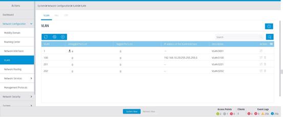
1. Click System View at the bottom of the page.
2. From the left navigation pane, select Network Configuration > VLAN.
3. Click the plus sign ![]() ,
and then perform the following tasks:
,
and then perform the following tasks:
¡ Create VLAN 100, and assign IP address to 192.168.10.2/24 VLAN-interface 100.
¡ Create VLANs 201 and 202.
Figure 2 Configuring VLANs
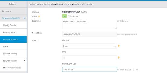
4. From the left navigation pane, select Network Configuration > Network Interfaces. On the Interfaces tab, configure GE1/0/1 as follows:
¡ Set the link type to Trunk.
¡ Enter 100,201,202 in the permit VLAN field.
Figure 3 Configuring interface GE1/0/1
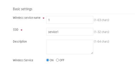
Configuring wireless services
1. Click Network View at the bottom of the page.
2. From the left navigation pane, select Wireless Configuration > Wireless Networks.
3. Click the plus sign ![]() ,
and then perform the following tasks:
,
and then perform the following tasks:
¡ Specify the wireless service name as 1.
¡ Set the SSID to service1.
¡ Enable the wireless service.
Figure 4 Configuring a wireless service
4. Repeat the previous step to configure wireless service 2. Set the SSID of wireless service 2 to service2.
Configuring the AP
1. Click Network View at the bottom of the page.
2. From the left navigation pane, select Wireless Configuration > AP Management.
3. Click the plus sign ![]() ,
and then perform the following tasks:
,
and then perform the following tasks:
¡ Specify the AP name as officeap.
¡ Specify the AP model and serial number.
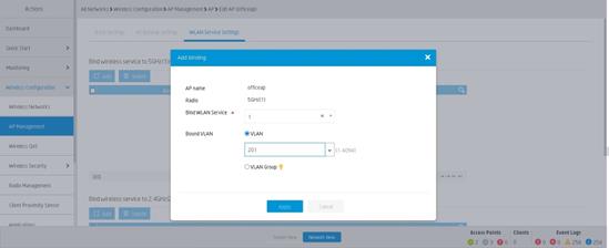
4. On the Wireless Configuration > AP Management page, click the edit icon for AP officeap, and bind wireless service 1 and VLAN 201 to the 5 GHz radio of the AP on the Wireless Service Settings tab.
Figure 5 Binding a wireless service to a radio
5. Repeat the previous step to bind wireless service 2 and VLAN 202 to the 2.4 GHz radio.
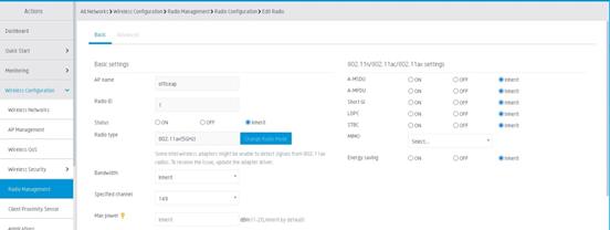
6. From the left navigation pane, select Wireless Configuration > Radio Management.
7. On the Radio Configuration tab, click the ![]() icon
to the upper right in the Radios of all APs section, and select the 5GHz radio
of AP officeap. Configure the radio as follows:
icon
to the upper right in the Radios of all APs section, and select the 5GHz radio
of AP officeap. Configure the radio as follows:
¡ Specify the radio mode as 802.11ax (5GHz).
¡ Select the working channel as 149.
¡ Enable the radio.
Figure 6 Configuring the 5GHz radio
8. Repeat the previous step to configure the 2.4 GHz radio. Set the radio mode to 802.11n (2.4GHz) and set the channel to 11.
Verifying the configuration
1. Click Network View at the bottom of the page.
2. From the left navigation pane, select Monitoring > Access Points. On the APs tab, verify that the AP is online.
3. From the left navigation pane, select Monitoring > Clients. In the By SSID section, verify that a 5GHz client is in the WLAN whose SSID is service1, and a 2.4GHz client is in the WLAN whose SSID is service2.
