- Table of Contents
-
- H3C S6860 Switch Series Configuration Examples-Release 26xx-6W100
- 01-Login Management Configuration Examples
- 02-RBAC Configuration Examples
- 03-Software Upgrade Examples
- 04-ISSU Configuration Examples
- 05-Software Patching Examples
- 06-Ethernet Link Aggregation Configuration Examples
- 07-Port Isolation Configuration Examples
- 08-Spanning Tree Configuration Examples
- 09-VLAN Configuration Examples
- 10-VLAN Tagging Configuration Examples
- 11-PBB Configuration Examples
- 12-DHCP Snooping Configuration Examples
- 13-Cross-Subnet Dynamic IP Address Allocation Configuration Examples
- 14-IPv6 over IPv4 Manual Tunneling with OSPFv3 Configuration Examples
- 15-ISATAP Tunnel and 6to4 Tunnel Configuration Examples
- 16-IPv6 over IPv4 GRE Tunnel Configuration Examples
- 17-GRE with OSPF Configuration Examples
- 18-OSPF Configuration Examples
- 19-IS-IS Configuration Examples
- 20-BGP Configuration Examples
- 21-Policy-Based Routing Configuration Examples
- 22-OSPFv3 Configuration Examples
- 23-IPv6 IS-IS Configuration Examples
- 24-Routing Policy Configuration Examples
- 25-IGMP Snooping Configuration Examples
- 26-IGMP Configuration Examples
- 27-BIDIR-PIM Configuration Examples
- 28-Multicast VPN Configuration Examples
- 29-MLD Snooping Configuration Examples
- 30-IPv6 Multicast VLAN Configuration Examples
- 31-Basic MPLS Configuration Examples
- 32-MPLS L3VPN Configuration Examples
- 33-ACL Configuration Examples
- 34-Control Plane-Based QoS Policy Configuration Examples
- 35-Traffic Policing Configuration Examples
- 36-GTS and Rate Limiting Configuration Examples
- 37-Priority Mapping and Queue Scheduling Configuration Examples
- 38-Traffic Filtering Configuration Examples
- 39-AAA Configuration Examples
- 40-Port Security Configuration Examples
- 41-Portal Configuration Examples
- 42-SSH Configuration Examples
- 43-IP Source Guard Configuration Examples
- 44-Ethernet OAM Configuration Examples
- 45-CFD Configuration Examples
- 46-DLDP Configuration Examples
- 47-VRRP Configuration Examples
- 48-BFD Configuration Examples
- 49-NTP Configuration Examples
- 50-SNMP Configuration Examples
- 51-NQA Configuration Examples
- 52-Mirroring Configuration Examples
- 53-sFlow Configuration Examples
- 54-FCoE Configuration Examples
- 55-SPBM Configuration Examples
- 56-OpenFlow Configuration Examples
- 57-MAC Address Table Configuration Examples
- 58-Static Multicast MAC Address Entry Configuration Examples
- 59-IP Unnumbered Configuration Examples
- 60-MVRP Configuration Examples
- 61-MCE Configuration Examples
- 62-Congestion Avoidance and Queue Scheduling Configuration Examples
- 63-Attack Protection Configuration Examples
- 64-Smart Link Configuration Examples
- 65-RRPP Configuration Examples
- 66-BGP Route Selection Configuration Examples
- 67-IS-IS Route Summarization Configuration Examples
- 68-IRF Configuration Examples
- 69-MPLS OAM Configuration Examples
- 70-MPLS TE Configuration Examples
- 71-VXLAN Configuration Examples
- 72-Comprehensive EVPN Configuration Examples
- 73-DRNI Configuration Examples
- 74-IRF 3.1 Configuration Examples
- 75-DRNI and EVPN Configuration Examples
- 76-VCF Fabric Configuration Examples
- 77-EVPN Networks and the Public Network Communication Configuration Examples
- Related Documents
-
| Title | Size | Download |
|---|---|---|
| 77-EVPN Networks and the Public Network Communication Configuration Examples | 100.89 KB |
|
|
|
H3C S6860 Switch Series |
|
EVPN Networks and the Public Network Communication Configuration Examples |
|
|
Copyright © 2018 New H3C Technologies Co., Ltd. All rights reserved.
No part of this manual may be reproduced or transmitted in any form or by any means without prior written consent of New H3C Technologies Co., Ltd.
Except for the trademarks of New H3C Technologies Co., Ltd., any trademarks that may be mentioned in this document are the property of their respective owners.
The information in this document is subject to change without notice.
General restrictions and guidelines
Feature compatibility and configuration restrictions for EVPN gateways
Ethernet service instance configuration restrictions
Access mode configuration restrictions
Example: Configuring communication between EVPN networks and the public network
Configuring IP addresses for interfaces
Configuring OSPF on the transport network
Creating the VXLANs and EVPN instances
Configuring the distributed EVPN gateways
Configuring BGP EVPN route advertisement
Mapping Ethernet service instances to VSIs
Introduction
This document provides examples for configuring communication between EVPN networks and the public network.
Ethernet Virtual Private Network (EVPN) is a Layer 2 VPN technology that provides both Layer 2 and Layer 3 connectivity between distant network sites across an IP network. EVPN uses MP-BGP in the control plane and VXLAN in the data plane.
Prerequisites
The configuration examples in this document were created and verified in a lab environment, and all the devices were started with the factory default configuration. When you are working on a live network, make sure you understand the potential impact of every command on your network.
This document assumes that you have basic knowledge of EVPN.
General restrictions and guidelines
Feature compatibility and configuration restrictions for EVPN gateways
An EVPN gateway processes the DSCP precedence in frames received from an AC as follows:
· For Layer 3 forwarding, the gateway always uses the DSCP precedence for priority mapping, regardless of whether you configure the qos trust dscp command on the incoming interface.
· For Layer 2 forwarding, the gateway uses the DSCP precedence for priority mapping only when the qos trust dscp command is configured on the incoming interface.
To ensure correct traffic forwarding, make sure all VSI interfaces on an EVPN gateway device use the same MAC address.
If both ARP flood suppression and local proxy ARP are enabled on a distributed EVPN gateway, only local proxy ARP takes effect. As a best practice, do not use these features together on distributed EVPN gateways.
Ethernet service instance configuration restrictions
You can create static Ethernet service instances on both a Layer 2 aggregate interface and its member ports and map the Ethernet service instances to VSIs. However, the Ethernet service instances on the aggregation member ports are down. For the Ethernet service instances to come up, you must remove the aggregation member ports from the aggregation group.
If an Ethernet service instance is configured with the encapsulation untagged criterion on a Layer 2 Ethernet or aggregate interface, you cannot apply a QoS policy for VLAN tag nesting to that interface. For more information about VLAN tag nesting, see QoS configuration in ACL and QoS Configuration Guide.
Access mode configuration restrictions
When you configure the access mode, follow these guidelines:
· Use the Ethernet access mode if an Ethernet service instance uses the encapsulation untagged criterion.
· Use the VLAN access mode if an Ethernet service instance uses the encapsulation s-vid { vlan-id [ only-tagged ] | vlan-id-list } criterion.
The default access mode is VLAN.
Example: Configuring communication between EVPN networks and the public network
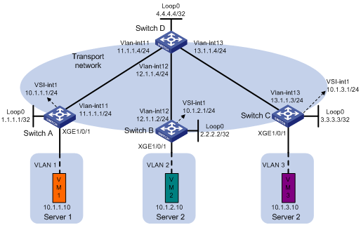
Network configuration
· Configure VXLAN 10, VXLAN 20, and VXLAN 30 on Switch A, Switch B, and Switch C to meet the following requirements:
? VXLAN 10 and VXLAN 20 are on the private network, and VXLAN 30 is on the public network.
? VXLAN 10 can communicate with VXLAN 20 and VXLAN 30, and VXLAN 20 is isolated from VXLAN 30.
· Configure Switch A, Switch B, and Switch C as distributed EVPN gateways to provide gateway services for the VXLANs.
· Configure Switch D as an RR to reflect BGP EVPN routes between Switch A, Switch B, and Switch C.
Analysis
For the switches to reach each other, configure a routing protocol on the switches to advertise routes for interfaces (including the loopback interfaces). In this example, OSPF is used.
For Layer 3 communication between VMs through distributed EVPN gateways, you must associate VSI interfaces with VPN instances and specify L3 VXLAN IDs for the VSI interfaces on the gateways.
To assign customer traffic of different VLANs to the corresponding VXLANs on Switch A, Switch B, and Switch C, you must perform the following tasks:
· Create an Ethernet service instance on the site-facing interface on each switch.
· Configure the Ethernet service instances to match customer traffic of different VLANs from the VMs.
· Map the Ethernet service instances to VSIs associated with VXLANs.
Software versions used
This configuration example was created and verified on S6860-CMW710-R2612.
Procedures
Configuring IP addresses for interfaces
# On Switch A, configure IP addresses for interfaces.
<SwitchA> system-view
[SwitchA] vlan 11
[SwitchA-vlan11] quit
[SwitchA] interface ten-gigabitethernet 1/0/2
[SwitchA-Ten-GigabitEthernet1/0/2] port link-type trunk
[SwitchA-Ten-GigabitEthernet1/0/2] port trunk permit vlan 11
[SwitchA-Ten-GigabitEthernet1/0/2] undo shutdown
[SwitchA-Ten-GigabitEthernet1/0/2] quit
[SwitchA] interface vlan-interface 11
[SwitchA-Vlan-interface11] ip address 11.1.1.1 24
[SwitchA-Vlan-interface11] undo shutdown
[SwitchA-Vlan-interface11] quit
[SwitchA] interface loopback 0
[SwitchA-LoopBack0] ip address 1.1.1.1 32
[SwitchA-LoopBack0] undo shutdown
[SwitchA-LoopBack0] quit
# Configure IP addresses for interfaces on Switch B, Switch C, and Switch D. The method is the same as Switch A. (Details not shown.)
# On VM 1, VM 2, and VM 3, specify 10.1.1.1, 10.1.2.1, and 10.1.3.1 as the gateway address, respectively. (Details not shown.)
Configuring OSPF on the transport network
Configuring Switch A
# Configure OSPF to advertise routes for Switch A.
[SwitchA] ospf 1
[SwitchA-ospf-1] area 0
[SwitchA-ospf-1-area-0.0.0.0] network 1.1.1.1 0.0.0.0
[SwitchA-ospf-1-area-0.0.0.0] network 11.1.1.0 0.0.0.255
[SwitchA-ospf-1-area-0.0.0.0] quit
[SwitchA-ospf-1] quit
Configuring Switch B
# Configure OSPF to advertise routes for Switch B.
<SwitchB> system-view
[SwitchB] ospf 1
[SwitchB-ospf-1] area 0
[SwitchB-ospf-1-area-0.0.0.0] network 2.2.2.2 0.0.0.0
[SwitchB-ospf-1-area-0.0.0.0] network 12.1.1.0 0.0.0.255
[SwitchB-ospf-1-area-0.0.0.0] quit
[SwitchB-ospf-1] quit
Configuring Switch C
# Configure OSPF to advertise routes for Switch C.
<SwitchC> system-view
[SwitchC] ospf 1
[SwitchC-ospf-1] area 0
[SwitchC-ospf-1-area-0.0.0.0] network 3.3.3.3 0.0.0.0
[SwitchC-ospf-1-area-0.0.0.0] network 13.1.1.0 0.0.0.255
[SwitchC-ospf-1-area-0.0.0.0] quit
[SwitchC-ospf-1] quit
Configuring Switch D
# Configure OSPF to advertise routes for Switch D.
<SwitchD> system-view
[SwitchD] ospf 1
[SwitchD-ospf-1] area 0
[SwitchD-ospf-1-area-0.0.0.0] network 4.4.4.4 0.0.0.0
[SwitchD-ospf-1-area-0.0.0.0] network 11.1.1.0 0.0.0.255
[SwitchD-ospf-1-area-0.0.0.0] network 12.1.1.0 0.0.0.255
[SwitchD-ospf-1-area-0.0.0.0] network 13.1.1.0 0.0.0.255
[SwitchD-ospf-1-area-0.0.0.0] quit
[SwitchD-ospf-1] quit
Creating the VXLANs and EVPN instances
Configuring Switch A
# Enable L2VPN.
[SwitchA] l2vpn enable
# Set the VXLAN hardware resource mode. For this mode to take effect, you must save the configuration and reboot the device. The save and reboot operations are not shown.
[SwitchA] hardware-resource vxlan l3gw8k
# Disable remote MAC address learning and remote ARP learning.
[SwitchA] vxlan tunnel mac-learning disable
[SwitchA] vxlan tunnel arp-learning disable
# Create VSI vpna and VXLAN 10.
[SwitchA] vsi vpna
[SwitchA-vsi-vpna] vxlan 10
[SwitchA-vsi-vpna-vxlan-10] quit
# Create an EVPN instance on VSI vpna.
[SwitchA-vsi-vpna] evpn encapsulation vxlan
# Configure the switch to automatically generate an RD and a route target for the EVPN instance.
[SwitchA-vsi-vpna-evpn-vxlan] route-distinguisher auto
[SwitchA-vsi-vpna-evpn-vxlan] vpn-target auto
[SwitchA-vsi-vpna-evpn-vxlan] quit
[SwitchA-vsi-vpna] quit
Configuring Switch B
# Enable L2VPN.
[SwitchB] l2vpn enable
# Set the VXLAN hardware resource mode. For this mode to take effect, you must save the configuration and reboot the device. The save and reboot operations are not shown.
[SwitchB] hardware-resource vxlan l3gw8k
# Disable remote MAC address learning and remote ARP learning.
[SwitchB] vxlan tunnel mac-learning disable
[SwitchB] vxlan tunnel arp-learning disable
# Create VSI vpnb and VXLAN 20.
[SwitchB] vsi vpnb
[SwitchB-vsi-vpnb] vxlan 20
[SwitchB-vsi-vpnb-vxlan-20] quit
# Create an EVPN instance on VSI vpnb.
[SwitchB-vsi-vpnb] evpn encapsulation vxlan
# Configure the switch to automatically generate an RD and a route target for the EVPN instance.
[SwitchB-vsi-vpnb-evpn-vxlan] route-distinguisher auto
[SwitchB-vsi-vpnb-evpn-vxlan] vpn-target auto
[SwitchB-vsi-vpnb-evpn-vxlan] quit
[SwitchB-vsi-vpnb] quit
Configuring Switch C
# Enable L2VPN.
[SwitchC] l2vpn enable
# Set the VXLAN hardware resource mode. For this mode to take effect, you must save the configuration and reboot the device. The save and reboot operations are not shown.
[SwitchC] hardware-resource vxlan l3gw8k
# Disable remote MAC address learning and remote ARP learning.
[SwitchC] vxlan tunnel mac-learning disable
[SwitchC] vxlan tunnel arp-learning disable
# Create VSI vpnc and VXLAN 30.
[SwitchC] vsi vpnc
[SwitchC-vsi-vpnc] vxlan 30
[SwitchC-vsi-vpnc-vxlan-30] quit
# Create an EVPN instance on VSI vpnc.
[SwitchC-vsi-vpnc] evpn encapsulation vxlan
# Configure the switch to automatically generate an RD and a route target for the EVPN instance.
[SwitchC-vsi-vpnc-evpn-vxlan] route-distinguisher auto
[SwitchC-vsi-vpnc-evpn-vxlan] vpn-target auto
[SwitchC-vsi-vpnc-evpn-vxlan] quit
[SwitchC-vsi-vpnc] quit
Configuring the distributed EVPN gateways
Configuring Switch A
# Configure RD and route target settings for VPN instance vpna.
[SwitchA] ip vpn-instance vpna
[SwitchA-vpn-instance-vpna] route-distinguisher 1:1
[SwitchA-vpn-instance-vpna] address-family ipv4
[SwitchA-vpn-ipv4-vpna] vpn-target 1:1
[SwitchA-vpn-ipv4-vpna] vpn-target 2:2 import-extcommunity
[SwitchA-vpn-ipv4-vpna] vpn-target 3:3 import-extcommunity
[SwitchA-vpn-ipv4-vpna] quit
[SwitchA-vpn-instance-vpna] address-family evpn
[SwitchA-vpn-evpn-vpna] vpn-target 1:1
[SwitchA-vpn-evpn-vpna] vpn-target 2:2 import-extcommunity
[SwitchA-vpn-evpn-vpna] vpn-target 3:3 import-extcommunity
[SwitchA-vpn-evpn-vpna] quit
[SwitchA-vpn-instance-vpna] quit
# Create and configure VSI-interface 1.
[SwitchA] interface vsi-interface 1
[SwitchA-Vsi-interface1] ip binding vpn-instance vpna
[SwitchA-Vsi-interface1] ip address 10.1.1.1 255.255.255.0
[SwitchA-Vsi-interface1] distributed-gateway local
[SwitchA-Vsi-interface1] local-proxy-arp enable
[SwitchA-Vsi-interface1] quit
# Create VSI-interface 2, associate the VSI interface with VPN instance vpna, and configure the L3 VXLAN ID as 1000 for the VPN instance.
[SwitchA] interface vsi-interface 2
[SwitchA-Vsi-interface2] ip binding vpn-instance vpna
[SwitchA-Vsi-interface2] l3-vni 1000
[SwitchA-Vsi-interface2] quit
# Create VSI-interface 3 and configure its L3 VXLAN ID as 2000 for matching routes from Switch B.
[SwitchA] interface vsi-interface 3
[SwitchA-Vsi-interface3] l3-vni 2000
[SwitchA-Vsi-interface3] quit
# Create VSI-interface 4 and configure its L3 VXLAN ID as 3000 for matching routes from Switch C.
[SwitchA] interface vsi-interface 4
[SwitchA-Vsi-interface4] l3-vni 3000
[SwitchA-Vsi-interface4] quit
# Specify VSI-interface 1 as the gateway interface for VSI vpna.
[SwitchA] vsi vpna
[SwitchA-vsi-vpna] gateway vsi-interface 1
[SwitchA-vsi-vpna] quit
Configuring Switch B
# Configure RD and route target settings for VPN instance vpnb.
[SwitchB] ip vpn-instance vpnb
[SwitchB-vpn-instance-vpnb] route-distinguisher 2:2
[SwitchB-vpn-instance-vpnb] address-family ipv4
[SwitchB-vpn-ipv4-vpnb] vpn-target 2:2
[SwitchB-vpn-ipv4-vpnb] vpn-target 1:1 import-extcommunity
[SwitchB-vpn-ipv4-vpnb] quit
[SwitchB-vpn-instance-vpnb] address-family evpn
[SwitchB-vpn-evpn-vpnb] vpn-target 2:2
[SwitchB-vpn-evpn-vpnb] vpn-target 1:1 import-extcommunity
[SwitchB-vpn-evpn-vpnb] quit
[SwitchB-vpn-instance-vpnb] quit
# Create and configure VSI-interface 1.
[SwitchB] interface vsi-interface 1
[SwitchB-Vsi-interface1] ip binding vpn-instance vpnb
[SwitchB-Vsi-interface1] ip address 10.1.2.1 255.255.255.0
[SwitchB-Vsi-interface1] distributed-gateway local
[SwitchB-Vsi-interface1] local-proxy-arp enable
[SwitchB-Vsi-interface1] quit
# Create VSI-interface 2, and configure its L3 VXLAN ID as 1000 for matching routes from Switch A.
[SwitchB] interface vsi-interface 2
[SwitchB-Vsi-interface2] l3-vni 1000
[SwitchB-Vsi-interface2] qui
# Create VSI-interface 3, associate the VSI interface with VPN instance vpnb, and configure the L3 VXLAN ID as 2000 for the VPN instance.
[SwitchB] interface vsi-interface 3
[SwitchB-Vsi-interface3] ip binding vpn-instance vpnb
[SwitchB-Vsi-interface3] l3-vni 2000
[SwitchB-Vsi-interface3] quit
# Create VSI-interface 4, and configure its L3 VXLAN ID as 3000 for matching routes from Switch C.
[SwitchA] interface vsi-interface 4
[SwitchA-Vsi-interface4] l3-vni 3000
[SwitchA-Vsi-interface4] quit
# Specify VSI-interface 1 as the gateway interface for VSI vpnb.
[SwitchB] vsi vpnb
[SwitchB-vsi-vpnb] gateway vsi-interface 1
[SwitchB-vsi-vpnb] quit
Configuring Switch C
# Configure RD, route target, and L3 VXLAN ID settings for the public instance.
[SwitchC] ip public-instance
[SwitchC-public-instance] route-distinguisher 3:3
[SwitchC-public-instance] l3-vni 3000
[SwitchC-public-instance] address-family ipv4
[SwitchC-public-instance-ipv4] vpn-target 3:3
[SwitchC-public-instance-ipv4] vpn-target 1:1 import-extcommunity
[SwitchC-public-instance-ipv4] quit
[SwitchC-public-instance] address-family evpn
[SwitchC-public-instance-evpn]vpn-target 3:3
[SwitchC-public-instance-evpn] vpn-target 1:1 import-extcommunity
[SwitchC-public-instance-evpn] quit
[SwitchC-public-instance] quit
# Create and configure VSI-interface 1.
[SwitchC] interface vsi-interface 1
[SwitchC-Vsi-interface1] ip address 10.1.3.1 255.255.255.0
[SwitchC-Vsi-interface1] distributed-gateway local
[SwitchC-Vsi-interface1] local-proxy-arp enable
[SwitchC-Vsi-interface1] quit
# Create VSI-interface 2, and configure its L3 VXLAN ID as 1000 for matching routes from Switch A.
[SwitchC] interface vsi-interface 2
[SwitchC-Vsi-interface2] l3-vni 1000
[SwitchC-Vsi-interface2] quit
# Create VSI-interface 3, and configure its L3 VXLAN ID as 2000 for matching routes from Switch B.
[SwitchC] interface vsi-interface 3
[SwitchC-Vsi-interface3] l3-vni 2000
[SwitchC-Vsi-interface3] quit
# Create VSI-interface 4 for the public instance, and configure the L3 VXLAN ID as 3000 for the VSI interface.
[SwitchC] interface vsi-interface 4
[SwitchC-Vsi-interface4] l3-vni 3000
[SwitchC-Vsi-interface4] quit
# Specify VSI-interface 1 as the gateway interface for VSI vpnc.
[SwitchC] vsi vpnc
[SwitchC-vsi-vpnc] gateway vsi-interface 1
[SwitchC-vsi-vpnc] quit
Configuring BGP EVPN route advertisement
Configuring Switch A
# Configure BGP to advertise BGP EVPN routes.
[SwitchA] bgp 200
[SwitchA-bgp-default] peer 4.4.4.4 as-number 200
[SwitchA-bgp-default] peer 4.4.4.4 connect-interface loopback 0
[SwitchA-bgp-default] address-family l2vpn evpn
[SwitchA-bgp-default-evpn] peer 4.4.4.4 enable
[SwitchA-bgp-default-evpn] quit
[SwitchA-bgp-default] quit
Configuring Switch B
# Configure BGP to advertise BGP EVPN routes.
[SwitchB] bgp 200
[SwitchB-bgp-default] peer 4.4.4.4 as-number 200
[SwitchB-bgp-default] peer 4.4.4.4 connect-interface loopback 0
[SwitchB-bgp-default] address-family l2vpn evpn
[SwitchB-bgp-default-evpn] peer 4.4.4.4 enable
[SwitchB-bgp-default-evpn] quit
[SwitchB-bgp-default] quit
Configuring Switch C
# Configure BGP to advertise BGP EVPN routes.
[SwitchC] bgp 200
[SwitchC-bgp-default] peer 4.4.4.4 as-number 200
[SwitchC-bgp-default] peer 4.4.4.4 connect-interface loopback 0
[SwitchC-bgp-default] address-family ipv4 unicast
[SwitchC-bgp-default-ipv4] quit
[SwitchC-bgp-default] address-family l2vpn evpn
[SwitchC-bgp-default-evpn] peer 4.4.4.4 enable
[SwitchC-bgp-default-evpn] quit
[SwitchC-bgp-default] quit
Configuring Switch D
# Establish BGP connections with other transport network switches.
[SwitchD] bgp 200
[SwitchD-bgp-default] group evpn
[SwitchD-bgp-default] peer 1.1.1.1 group evpn
[SwitchD-bgp-default] peer 2.2.2.2 group evpn
[SwitchD-bgp-default] peer 3.3.3.3 group evpn
[SwitchD-bgp-default] peer evpn as-number 200
[SwitchD-bgp-default] peer evpn connect-interface loopback 0
# Configure BGP to advertise BGP EVPN routes, and disable route target filtering for BGP EVPN routes.
[SwitchD-bgp-default] address-family l2vpn evpn
[SwitchD-bgp-default-evpn] peer evpn enable
[SwitchD-bgp-default-evpn] undo policy vpn-target
# Configure Switch D as an RR.
[SwitchD-bgp-default-evpn] peer evpn reflect-client
[SwitchD-bgp-default-evpn] quit
[SwitchD-bgp-default] quit
Mapping Ethernet service instances to VSIs
Configuring Switch A
# Create Ethernet service instance 1000 on site-facing interface Ten-GigabitEthernet 1/0/1 to match VLAN 1.
[SwitchA] interface ten-gigabitethernet 1/0/1
[SwitchA-Ten-GigabitEthernet1/0/1] service-instance 1000
[SwitchA-Ten-GigabitEthernet1/0/1-srv1000] encapsulation s-vid 1
# Map Ethernet service instance 1000 to VSI vpna.
[SwitchA-Ten-GigabitEthernet1/0/1-srv1000] xconnect vsi vpna
[SwitchA-Ten-GigabitEthernet1/0/1-srv1000] quit
[SwitchA-Ten-GigabitEthernet1/0/1] quit
Configuring Switch B
# Create Ethernet service instance 1000 on site-facing interface Ten-GigabitEthernet 1/0/1 to match VLAN 2.
[SwitchB] interface ten-gigabitethernet 1/0/1
[SwitchB-Ten-GigabitEthernet1/0/1] service-instance 1000
[SwitchB-Ten-GigabitEthernet1/0/1-srv1000] encapsulation s-vid 2
# Map Ethernet service instance 1000 to VSI vpnb.
[SwitchB-Ten-GigabitEthernet1/0/1-srv1000] xconnect vsi vpnb
[SwitchB-Ten-GigabitEthernet1/0/1-srv1000] quit
[SwitchB-Ten-GigabitEthernet1/0/1] quit
Configuring Switch C
# Create Ethernet service instance 1000 on site-facing interface Ten-GigabitEthernet 1/0/1 to match VLAN 3.
[SwitchC] interface ten-gigabitethernet 1/0/1
[SwitchC-Ten-GigabitEthernet1/0/1] service-instance 1000
[SwitchC-Ten-GigabitEthernet1/0/1-srv1000] encapsulation s-vid 3
# Map Ethernet service instance 1000 to VSI vpnc.
[SwitchC-Ten-GigabitEthernet1/0/1-srv1000] xconnect vsi vpnc
[SwitchC-Ten-GigabitEthernet1/0/1-srv1000] quit
[SwitchC-Ten-GigabitEthernet1/0/1] quit
Verifying the configuration
1. Verify the distributed EVPN gateway settings on Switch A:
# Verify that Switch A has advertised the IP prefix advertisement routes for the gateways and the MAC/IP advertisement routes and IMET routes for each VSI. Verify that Switch A has received the IP prefix advertisement routes for the gateways and the MAC/IP advertisement routes and IMET routes for each VSI from Switch B and Switch C.
[SwitchA] display bgp l2vpn evpn
BGP local router ID is 1.1.1.1
Status codes: * - valid, > - best, d - dampened, h - history,
s - suppressed, S - stale, i - internal, e - external
a - additional-path
Origin: i - IGP, e - EGP, ? - incomplete
Total number of routes from all PEs: 9
Route distinguisher: 1:1(vpna)
Total number of routes: 3
Network NextHop MED LocPrf PrefVal Path/Ogn
* >i [2][0][48][582e-d6b2-0906][32][10.1.2.10]/136
2.2.2.2 0 100 0 i
* >i [2][0][48][9a50-488c-1106][32][10.1.3.10]/136
3.3.3.3 0 100 0 i
* > [5][0][24][10.1.1.0]/80
0.0.0.0 0 100 32768 i
Route distinguisher: 1:10
Total number of routes: 2
Network NextHop MED LocPrf PrefVal Path/Ogn
* > [2][0][48][582e-aaec-0806][32][10.1.1.10]/136
0.0.0.0 0 100 32768 i
* > [3][0][32][1.1.1.1]/80
0.0.0.0 0 100 32768 i
Route distinguisher: 1:20
Total number of routes: 1
Network NextHop MED LocPrf PrefVal Path/Ogn
* >i [2][0][48][582e-d6b2-0906][32][10.1.2.10]/136
2.2.2.2 0 100 0 i
Route distinguisher: 1:30
Total number of routes: 1
Network NextHop MED LocPrf PrefVal Path/Ogn
* >i [2][0][48][9a50-488c-1106][32][10.1.3.10]/136
3.3.3.3 0 100 0 i
Route distinguisher: 2:2
Total number of routes: 1
Network NextHop MED LocPrf PrefVal Path/Ogn
* >i [5][0][24][10.1.2.0]/80
2.2.2.2 0 100 0 i
Route distinguisher: 3:3
Total number of routes: 1
Network NextHop MED LocPrf PrefVal Path/Ogn
* >i [5][0][24][10.1.3.0]/80
3.3.3.3 0 100 0 i
# Verify that the VXLAN tunnel interfaces are up on Switch A.
[SwitchA] display interface tunnel
Tunnel0
Current state: UP
Line protocol state: UP
Description: Tunnel0 Interface
Bandwidth: 64 kbps
Maximum transmission unit: 1464
Internet protocol processing: Disabled
Output queue - Urgent queuing: Size/Length/Discards 0/100/0
Output queue - Protocol queuing: Size/Length/Discards 0/500/0
Output queue - FIFO queuing: Size/Length/Discards 0/75/0
Last clearing of counters: Never
Tunnel source 1.1.1.1, destination 2.2.2.2
Tunnel protocol/transport UDP_VXLAN/IP
Last 300 seconds input rate: 0 bytes/sec, 0 bits/sec, 0 packets/sec
Last 300 seconds output rate: 0 bytes/sec, 0 bits/sec, 0 packets/sec
Input: 15 packets, 1470 bytes, 0 drops
Output: 15 packets, 1470 bytes, 0 drops
Tunnel1
Current state: UP
Line protocol state: UP
Description: Tunnel1 Interface
Bandwidth: 64 kbps
Maximum transmission unit: 1464
Internet protocol processing: Disabled
Output queue - Urgent queuing: Size/Length/Discards 0/100/0
Output queue - Protocol queuing: Size/Length/Discards 0/500/0
Output queue - FIFO queuing: Size/Length/Discards 0/75/0
Last clearing of counters: Never
Tunnel source 1.1.1.1, destination 3.3.3.3
Tunnel protocol/transport UDP_VXLAN/IP
Last 300 seconds input rate: 0 bytes/sec, 0 bits/sec, 0 packets/sec
Last 300 seconds output rate: 0 bytes/sec, 0 bits/sec, 0 packets/sec
Input: 22 packets, 2156 bytes, 0 drops
Output: 23 packets, 2254 bytes, 0 drops
# Verify that the VSI interfaces are up on Switch A.
[SwitchA] display interface vsi-interface
Vsi-interface1
Current state: UP
Line protocol state: UP
Description: Vsi-interface1 Interface
Bandwidth: 1000000 kbps
Maximum transmission unit: 1444
Internet address: 10.1.1.1/24 (primary)
IP packet frame type: Ethernet II, hardware address: 582e-81f2-0600
IPv6 packet frame type: Ethernet II, hardware address: 582e-81f2-0600
Physical: Unknown, baudrate: 1000000 kbps
Last clearing of counters: Never
Input (total): 0 packets, 0 bytes
Output (total): 2625 packets, 138432 bytes
Vsi-interface2
Current state: UP
Line protocol state: UP
Description: Vsi-interface2 Interface
Bandwidth: 1000000 kbps
Maximum transmission unit: 1444
Internet protocol processing: Disabled
IP packet frame type: Ethernet II, hardware address: 582e-81f2-0600
IPv6 packet frame type: Ethernet II, hardware address: 582e-81f2-0600
Physical: Unknown, baudrate: 1000000 kbps
Last clearing of counters: Never
Input (total): 0 packets, 0 bytes
Output (total): 0 packets, 0 bytes
Vsi-interface3
Current state: UP
Line protocol state: UP
Description: Vsi-interface3 Interface
Bandwidth: 1000000 kbps
Maximum transmission unit: 1444
Internet protocol processing: Disabled
IP packet frame type: Ethernet II, hardware address: 582e-81f2-0600
IPv6 packet frame type: Ethernet II, hardware address: 582e-81f2-0600
Physical: Unknown, baudrate: 1000000 kbps
Last clearing of counters: Never
Input (total): 0 packets, 0 bytes
Output (total): 0 packets, 0 bytes
Vsi-interface4
Current state: UP
Line protocol state: UP
Description: Vsi-interface4 Interface
Bandwidth: 1000000 kbps
Maximum transmission unit: 1444
Internet protocol processing: Disabled
IP packet frame type: Ethernet II, hardware address: 582e-81f2-0600
IPv6 packet frame type: Ethernet II, hardware address: 582e-81f2-0600
Physical: Unknown, baudrate: 1000000 kbps
Last clearing of counters: Never
Input (total): 0 packets, 0 bytes
Output (total): 0 packets, 0 bytes
# Verify that the VXLAN tunnels have been assigned to the VXLANs, and that the VSI interfaces are the gateway interfaces of their respective VXLANs.
[SwitchA] display l2vpn vsi verbose
VSI Name: Auto_L3VNI1000_2
VSI Index : 1
VSI State : Down
MTU : 1500
Bandwidth : Unlimited
Broadcast Restrain : Unlimited
Multicast Restrain : Unlimited
Unknown Unicast Restrain: Unlimited
MAC Learning : Enabled
MAC Table Limit : -
MAC Learning rate : -
Drop Unknown : -
Flooding : Enabled
Statistics : Disabled
Gateway Interface : VSI-interface 2
VXLAN ID : 1000
VSI Name: Auto_L3VNI2000_3
VSI Index : 2
VSI State : Down
MTU : 1500
Bandwidth : Unlimited
Broadcast Restrain : Unlimited
Multicast Restrain : Unlimited
Unknown Unicast Restrain: Unlimited
MAC Learning : Enabled
MAC Table Limit : -
MAC Learning rate : -
Drop Unknown : -
Flooding : Enabled
Statistics : Disabled
Gateway Interface : VSI-interface 3
VXLAN ID : 2000
VSI Name: Auto_L3VNI3000_4
VSI Index : 3
VSI State : Down
MTU : 1500
Bandwidth : Unlimited
Broadcast Restrain : Unlimited
Multicast Restrain : Unlimited
Unknown Unicast Restrain: Unlimited
MAC Learning : Enabled
MAC Table Limit : -
MAC Learning rate : -
Drop Unknown : -
Flooding : Enabled
Statistics : Disabled
Gateway Interface : VSI-interface 4
VXLAN ID : 3000
VSI Name: vpna
VSI Index : 0
VSI State : Up
MTU : 1500
Bandwidth : Unlimited
Broadcast Restrain : Unlimited
Multicast Restrain : Unlimited
Unknown Unicast Restrain: Unlimited
MAC Learning : Enabled
MAC Table Limit : -
MAC Learning rate : -
Drop Unknown : -
Flooding : Enabled
Statistics : Disabled
Gateway Interface : VSI-interface 1
VXLAN ID : 10
ACs:
AC Link ID State Type
XGE1/0/1 srv1000 0 Up Manual
# Verify that Switch A has created ARP entries for the VMs and for the next hops of BGP EVPN routes.
[SwitchA] display arp
Type: S-Static D-Dynamic O-Openflow R-Rule M-Multiport I-Invalid
IP address MAC address VLAN/VSI Interface/Link ID Aging Type
10.1.1.10 582e-aaec-0806 0 0 10 D
11.1.1.4 582c-1385-0517 -- Vlan11 14 D
2.2.2.2 582e-8ba6-0700 2 Tunnel0 -- R
3.3.3.3 9a51-95ba-1000 3 Tunnel1 -- R
2. Verify that VM 1 can communicate with VM 2 and VM 3, and VM 2 cannot communicate with VM 3. (Details not shown.)
Configuration files
· Switch A:
#
sysname SwitchA
#
ip vpn-instance vpna
route-distinguisher 1:1
#
address-family ipv4
vpn-target 1:1 2:2 3:3 import-extcommunity
vpn-target 1:1 export-extcommunity
#
address-family evpn
vpn-target 1:1 2:2 3:3 import-extcommunity
vpn-target 1:1 export-extcommunity
#
vxlan tunnel mac-learning disable
#
ospf 1
area 0.0.0.0
network 1.1.1.1 0.0.0.0
network 11.1.1.0 0.0.0.255
#
vlan 11
#
vlan 1
#
l2vpn enable
vxlan tunnel arp-learning disable
#
vsi vpna
gateway vsi-interface 1
vxlan 10
evpn encapsulation vxlan
route-distinguisher auto
vpn-target auto export-extcommunity
vpn-target auto import-extcommunity
#
interface LoopBack0
ip address 1.1.1.1 255.255.255.255
#
interface Vlan-interface11
ip address 11.1.1.1 255.255.255.0
#
interface Ten-GigabitEthernet1/0/1
port link-mode bridge
#
service-instance 1000
encapsulation s-vid 1
xconnect vsi vpna
#
interface Ten-GigabitEthernet1/0/2
port link-mode bridge
port link-type trunk
port trunk permit vlan 1 11
#
interface Vsi-interface1
ip binding vpn-instance vpna
ip address 10.1.1.1 255.255.255.0
local-proxy-arp enable
distributed-gateway local
#
interface Vsi-interface2
ip binding vpn-instance vpna
l3-vni 1000
#
interface Vsi-interface3
l3-vni 2000
#
interface Vsi-interface4
l3-vni 3000
#
bgp 200
peer 4.4.4.4 as-number 200
peer 4.4.4.4 connect-interface LoopBack0
#
address-family l2vpn evpn
peer 4.4.4.4 enable
#
Return
· Switch B:
#
sysname SwitchB
#
ip vpn-instance vpnb
route-distinguisher 2:2
#
address-family ipv4
vpn-target 2:2 1:1 import-extcommunity
vpn-target 2:2 export-extcommunity
#
address-family evpn
vpn-target 2:2 1:1 import-extcommunity
vpn-target 2:2 export-extcommunity
#
vxlan tunnel mac-learning disable
#
ospf 1
area 0.0.0.0
network 2.2.2.2 0.0.0.0
network 12.1.1.0 0.0.0.255
#
vlan 12
#
vlan 2
#
l2vpn enable
vxlan tunnel arp-learning disable
#
vsi vpnb
gateway vsi-interface 1
vxlan 20
evpn encapsulation vxlan
route-distinguisher auto
vpn-target auto export-extcommunity
vpn-target auto import-extcommunity
#
interface LoopBack0
ip address 2.2.2.2 255.255.255.255
#
interface Vlan-interface12
ip address 12.1.1.1 255.255.255.0
#
interface Ten-GigabitEthernet1/0/1
port link-mode bridge
#
service-instance 1000
encapsulation s-vid 2
xconnect vsi vpnb
#
interface Ten-GigabitEthernet1/0/2
port link-mode bridge
port link-type trunk
port trunk permit vlan 2 12
#
interface Vsi-interface1
ip binding vpn-instance vpna
ip address 10.1.2.1 255.255.255.0
local-proxy-arp enable
distributed-gateway local
#
interface Vsi-interface2
l3-vni 1000
#
interface Vsi-interface3
ip binding vpn-instance vpnb
l3-vni 2000
#
interface Vsi-interface4
l3-vni 3000
#
bgp 200
peer 4.4.4.4 as-number 200
peer 4.4.4.4 connect-interface LoopBack0
#
address-family l2vpn evpn
peer 4.4.4.4 enable
#
return
· Switch C:
#
sysname SwitchC
#
ip public-instance
route-distinguisher 3:3
#
address-family ipv4
vpn-target 3:3 1:1 import-extcommunity
vpn-target 3:3 export-extcommunity
#
address-family evpn
vpn-target 3:3 1:1 import-extcommunity
vpn-target 3:3 export-extcommunity
#
vxlan tunnel mac-learning disable
#
ospf 1
area 0.0.0.0
network 3.3.3.3 0.0.0.0
network 13.1.1.0 0.0.0.255
#
vlan 13
#
vlan 3
#
l2vpn enable
vxlan tunnel arp-learning disable
#
vsi vpnc
gateway vsi-interface 1
vxlan 30
evpn encapsulation vxlan
route-distinguisher auto
vpn-target auto export-extcommunity
vpn-target auto import-extcommunity
#
interface LoopBack0
ip address 3.3.3.3 255.255.255.255
#
interface Vlan-interface13
ip address 13.1.1.1 255.255.255.0
#
interface Ten-GigabitEthernet1/0/1
port link-mode bridge
#
service-instance 1000
encapsulation s-vid 3
xconnect vsi vpnc
#
interface Ten-GigabitEthernet1/0/2
port link-mode bridge
port link-type trunk
port trunk permit vlan 3 13
#
interface Vsi-interface1
ip binding vpn-instance vpna
ip address 10.1.3.1 255.255.255.0
local-proxy-arp enable
distributed-gateway local
#
interface Vsi-interface2
l3-vni 1000
#
interface Vsi-interface3
l3-vni 2000
#
interface Vsi-interface4
l3-vni 3000
#
bgp 200
peer 4.4.4.4 as-number 200
peer 4.4.4.4 connect-interface LoopBack0
#
address-family ipv4
peer 4.4.4.4 enable
#
address-family l2vpn evpn
peer 4.4.4.4 enable
#
return
· Switch D:
#
sysname SwitchD
#
ospf 1
area 0.0.0.0
network 4.4.4.4 0.0.0.0
network 11.1.1.0 0.0.0.255
network 12.1.1.0 0.0.0.255
network 13.1.1.0 0.0.0.255
#
vlan 11
#
vlan 12
#
vlan 13
#
interface LoopBack0
ip address 4.4.4.4 255.255.255.255
#
interface Vlan-interface11
ip address 11.1.1.1 255.255.255.0
#
interface Vlan-interface12
ip address 12.1.1.1 255.255.255.0
#
interface Vlan-interface13
ip address 13.1.1.1 255.255.255.0
#
interface Ten-GigabitEthernet1/0/1
port link-mode bridge
port link-type trunk
port trunk permit vlan 11
#
interface Ten-GigabitEthernet1/0/2
port link-mode bridge
port link-type trunk
port trunk permit vlan 12
#
interface Ten-GigabitEthernet1/0/3
port link-mode bridge
port link-type trunk
port trunk permit vlan 13
#
bgp 200
group evpn internal
peer evpn connect-interface LoopBack0
peer 1.1.1.1 group evpn
peer 2.2.2.2 group evpn
peer 3.3.3.3 group evpn
#
address-family l2vpn evpn
undo policy vpn-target
peer evpn enable
peer evpn reflect-client
#
return
Related documentation
· H3C S6860 Switch Series EVPN Command Reference-Release 26xx
· H3C S6860 Switch Series EVPN Configuration Guide-Release 26xx