- Table of Contents
-
- H3C S6860 Switch Series Configuration Examples-Release 26xx-6W100
- 01-Login Management Configuration Examples
- 02-RBAC Configuration Examples
- 03-Software Upgrade Examples
- 04-ISSU Configuration Examples
- 05-Software Patching Examples
- 06-Ethernet Link Aggregation Configuration Examples
- 07-Port Isolation Configuration Examples
- 08-Spanning Tree Configuration Examples
- 09-VLAN Configuration Examples
- 10-VLAN Tagging Configuration Examples
- 11-PBB Configuration Examples
- 12-DHCP Snooping Configuration Examples
- 13-Cross-Subnet Dynamic IP Address Allocation Configuration Examples
- 14-IPv6 over IPv4 Manual Tunneling with OSPFv3 Configuration Examples
- 15-ISATAP Tunnel and 6to4 Tunnel Configuration Examples
- 16-IPv6 over IPv4 GRE Tunnel Configuration Examples
- 17-GRE with OSPF Configuration Examples
- 18-OSPF Configuration Examples
- 19-IS-IS Configuration Examples
- 20-BGP Configuration Examples
- 21-Policy-Based Routing Configuration Examples
- 22-OSPFv3 Configuration Examples
- 23-IPv6 IS-IS Configuration Examples
- 24-Routing Policy Configuration Examples
- 25-IGMP Snooping Configuration Examples
- 26-IGMP Configuration Examples
- 27-BIDIR-PIM Configuration Examples
- 28-Multicast VPN Configuration Examples
- 29-MLD Snooping Configuration Examples
- 30-IPv6 Multicast VLAN Configuration Examples
- 31-Basic MPLS Configuration Examples
- 32-MPLS L3VPN Configuration Examples
- 33-ACL Configuration Examples
- 34-Control Plane-Based QoS Policy Configuration Examples
- 35-Traffic Policing Configuration Examples
- 36-GTS and Rate Limiting Configuration Examples
- 37-Priority Mapping and Queue Scheduling Configuration Examples
- 38-Traffic Filtering Configuration Examples
- 39-AAA Configuration Examples
- 40-Port Security Configuration Examples
- 41-Portal Configuration Examples
- 42-SSH Configuration Examples
- 43-IP Source Guard Configuration Examples
- 44-Ethernet OAM Configuration Examples
- 45-CFD Configuration Examples
- 46-DLDP Configuration Examples
- 47-VRRP Configuration Examples
- 48-BFD Configuration Examples
- 49-NTP Configuration Examples
- 50-SNMP Configuration Examples
- 51-NQA Configuration Examples
- 52-Mirroring Configuration Examples
- 53-sFlow Configuration Examples
- 54-FCoE Configuration Examples
- 55-SPBM Configuration Examples
- 56-OpenFlow Configuration Examples
- 57-MAC Address Table Configuration Examples
- 58-Static Multicast MAC Address Entry Configuration Examples
- 59-IP Unnumbered Configuration Examples
- 60-MVRP Configuration Examples
- 61-MCE Configuration Examples
- 62-Congestion Avoidance and Queue Scheduling Configuration Examples
- 63-Attack Protection Configuration Examples
- 64-Smart Link Configuration Examples
- 65-RRPP Configuration Examples
- 66-BGP Route Selection Configuration Examples
- 67-IS-IS Route Summarization Configuration Examples
- 68-IRF Configuration Examples
- 69-MPLS OAM Configuration Examples
- 70-MPLS TE Configuration Examples
- 71-VXLAN Configuration Examples
- 72-Comprehensive EVPN Configuration Examples
- 73-DRNI Configuration Examples
- 74-IRF 3.1 Configuration Examples
- 75-DRNI and EVPN Configuration Examples
- 76-VCF Fabric Configuration Examples
- 77-EVPN Networks and the Public Network Communication Configuration Examples
- Related Documents
-
| Title | Size | Download |
|---|---|---|
| 74-IRF 3.1 Configuration Examples | 107.24 KB |
|
|
|
H3C S6860 Switch Series |
|
IRF 3.1 Configuration Examples |
|
|
Copyright © 2018 New H3C Technologies Co., Ltd. All rights reserved.
No part of this manual may be reproduced or transmitted in any form or by any means without prior written consent of New H3C Technologies Co., Ltd.
Except for the trademarks of New H3C Technologies Co., Ltd., any trademarks that may be mentioned in this document are the property of their respective owners.
The information in this document is subject to change without notice.
Contents
Example: Setting up an IRF 3.1 system
Configuring cascade ports for PEXs on the parent fabric
Configuring the gateway settings on the IRF 3.1 system
Configuring access layer devices
Introduction
This document provides examples for setting up an IRF 3.1 system.
IRF 3.1 integrates multiple lower-layer devices with a higher-layer IRF fabric to provide high-density, low-cost connectivity at the access layer. IRF 3.1 is implemented based on IEEE 802.1BR.
In an IRF 3.1 system, the higher-layer IRF fabric is called the parent fabric and the lower-layer devices are called bridge port extenders (PEXs). You manage and configure the PEXs from the parent fabric as if they were interface modules on the parent fabric.
Prerequisites
The configuration examples in this document were created and verified in a lab environment, and all the devices were started with the factory default configuration. When you are working on a live network, make sure you understand the potential impact of every command on your network.
This document assumes that you have basic knowledge of IRF 3.1.
Example: Setting up an IRF 3.1 system
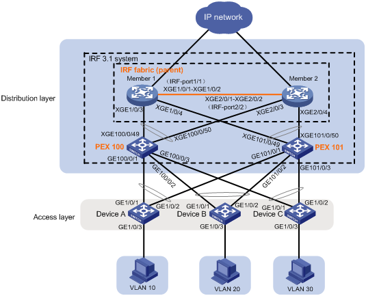
Network configuration
As shown in Figure 1:
· Use Member 1 and Member 2 to set up an IRF fabric at the distribution layer. The two devices are H3C S6860 switches.
· Use the IRF fabric as the parent fabric and attach PEXs to the parent fabric to set up an IRF 3.1 system.
· The IRF 3.1 system acts as the gateway for users in VLANs 10, 20, and 30.
· Access layer devices are connected to the IRF 3.1 system through multichassis link aggregation.
Software versions used
This configuration example was created and verified on S6860-CMW710-R2612.
Restrictions and guidelines
When you set up the parent fabric, you must set the device operating mode of all member devices to switch mode.
To assign extended ports on multiple PEXs to the same Layer 2 extended-link aggregation group, make sure the PEXs meet the following requirements:
· The PEXs belong to the same switch series.
· The PEXs are in the same PEX group.
· The PEXs are at the same tier.
Procedures
Setting up the parent fabric
1. Configure Member 1:
# Set the device operating mode to switch mode.
<Sysname> system-view
[Sysname] pex system-working-mode switch
# Shut down Ten-GigabitEthernet 1/0/1 and Ten-GigabitEthernet 1/0/2.
[Sysname] interface range ten-gigabitethernet 1/0/1 to ten-gigabitethernet 1/0/2
[Sysname-if-range] shutdown
[Sysname-if-range] quit
# Bind Ten-GigabitEthernet 1/0/1 and Ten-GigabitEthernet 1/0/2 to IRF-port 1/1.
[Sysname] irf-port 1/1
[Sysname-irf-port1/1] port group interface ten-gigabitethernet 1/0/1
[Sysname-irf-port1/1] port group interface ten-gigabitethernet 1/0/2
[Sysname-irf-port1/1] quit
# Bring up Ten-GigabitEthernet 1/0/1 and Ten-GigabitEthernet 1/0/2 and save the configuration.
[Sysname] interface range ten-gigabitethernet 1/0/1 to ten-gigabitethernet 1/0/2
[Sysname-if-range] undo shutdown
[Sysname-if-range] quit
[Sysname] save
# Activate the IRF port configuration.
[Sysname] irf-port-configuration active
2. Configure Member 2:
# Set the device operating mode to switch mode.
<Sysname> system-view
[Sysname] pex system-working-mode switch
# Change the IRF member ID to 2 and reboot the device for the new member ID to take effect.
[Sysname] irf member 1 renumber 2
Renumbering the member ID may result in configuration change or loss. Continue? [Y/N]:y
[Sysname] quit
<Sysname> reboot
# Log in to the device and shut down Ten-GigabitEthernet 2/0/1 and Ten-GigabitEthernet 2/0/2.
<Sysname> system-view
[Sysname] interface range ten-gigabitethernet 2/0/1 to ten-gigabitethernet 2/0/2
[Sysname-if-range] shutdown
[Sysname-if-range] quit
# Bind Ten-GigabitEthernet 2/0/1 and Ten-GigabitEthernet 2/0/2 to IRF-port 2/2.
[Sysname] irf-port 2/2
[Sysname-irf-port2/2] port group interface ten-gigabitethernet 2/0/1
[Sysname-irf-port2/2] port group interface ten-gigabitethernet 2/0/2
[Sysname-irf-port2/2] quit
# Bring up Ten-GigabitEthernet 2/0/1 and Ten-GigabitEthernet 2/0/2 and save the configuration.
[Sysname] interface range ten-gigabitethernet 2/0/1 to ten-gigabitethernet 2/0/2
[Sysname-if-range] undo shutdown
[Sysname-if-range] quit
[Sysname] save
# Connect the IRF physical interfaces on Member 2 to the IRF physical interfaces on Member 1. (Details not shown.)
# Activate the IRF port configuration on Member 2.
[Sysname] irf-port-configuration active
Member 1 and Member 2 perform master election. The device that fails the election will reboot automatically to form an IRF fabric with the other device.
Configuring cascade ports for PEXs on the parent fabric
# Enter system view.
<Sysname> system-view
# Enable LLDP globally.
[Sysname] lldp global enable
# Create PEX group 1.
[Sysname] pex group 1
[Sysname-pex-group-1] quit
# Create Layer 2 aggregate interface Bridge-Aggregation 100. The aggregate interface will act as the cascade port connecting to the PEX in slot 100. For easy maintenance, this example assigns the aggregate interface the same number as the PEX virtual slot.
[Sysname] interface bridge-aggregation 100
# Enable PEX connection capability on Bridge-Aggregation 100 and assign Bridge-Aggregation 100 to PEX group 1.
[Sysname-Bridge-Aggregation100] pex-capability enable group 1
The aggregate interface is operating in dynamic aggregation mode and acting as an STP edge port.
# Assign virtual slot number 100 to the PEX.
[Sysname-Bridge-Aggregation100] pex associate slot 100
[Sysname-Bridge-Aggregation100] quit
# Enable LLDP on Ten-GigabitEthernet 1/0/3 and Ten-GigabitEthernet 2/0/3 in interface range view. By default, LLDP is enabled on a port.
[Sysname] interface range ten-gigabitethernet 1/0/3 ten-gigabitethernet 2/0/3
[Sysname-if-range] lldp enable
# Assign Ten-GigabitEthernet 1/0/3 and Ten-GigabitEthernet 2/0/3 to aggregation group 100. The ports will act as the cascade member interfaces.
[Sysname-if-range] port link-aggregation group 100
[Sysname-if-range] quit
# Create Layer 2 aggregate interface Bridge-Aggregation 101. The aggregate interface will act as the cascade port connecting to the PEX in slot 101.
[Sysname] interface bridge-aggregation 101
# Enable PEX connection capability on Bridge-Aggregation 101 and assign the interface to PEX group 1.
[Sysname-Bridge-Aggregation101] pex-capability enable group 1
The aggregate interface is operating in dynamic aggregation mode and acting as an STP edge port.
# Assign virtual slot number 101 to the PEX.
[Sysname-Bridge-Aggregation101] pex associate slot 101
[Sysname-Bridge-Aggregation101] quit
# Enable LLDP on Ten-GigabitEthernet 1/0/4 and Ten-GigabitEthernet 2/0/4 in interface range view. By default, LLDP is enabled on a port.
[Sysname] interface range ten-gigabitethernet 1/0/4 ten-gigabitethernet 2/0/4
[Sysname-if-range] lldp enable
# Assign Ten-GigabitEthernet 1/0/4 and Ten-GigabitEthernet 2/0/4 to aggregation group 101. The ports will act as the cascade member interfaces.
[Sysname-if-range] port link-aggregation group 101
[Sysname-if-range] quit
Configuring PEXs
Configure the devices to be used as PEXs to operate in auto or PEX mode. This example uses PEX 100 to describe the configuration procedure. You can configure PEX 101 in the same way PEX 100 is configured.
# Configure PEX 100 to operate in auto mode. By default, the operating mode is auto.
<Sysname> system-view
[Sysname] pex system-working-mode auto
# Save the running configuration.
[Sysname] save
# Select upstream member interfaces. In this example, Ten-GigabitEthernet 1/0/49 and Ten-GigabitEthernet 1/0/50 are used. For information about candidate upstream member interfaces, see the configuration guides for the PEX. (Details not shown.)
# Connect the upstream member interfaces on PEX 100 to the cascade member interfaces on the parent fabric. (Details not shown.)
Configuring the gateway settings on the IRF 3.1 system
# Enter system view.
<Sysname> system-view
# Create VLANs 10, 20, and 30.
[Sysname] vlan 10 20 30
# Create VLAN-interface 10 and assign IP address 192.168.1.1/24 to the VLAN interface.
[Sysname] interface vlan-interface 10
[Sysname-Vlan-interface10] ip address 192.168.1.1 24
[Sysname-Vlan-interface10] quit
# Create VLAN-interface 20 and assign IP address 192.168.2.1/24 to the VLAN interface.
[Sysname] interface vlan-interface 20
[Sysname-Vlan-interface20] ip address 192.168.2.1 24
[Sysname-Vlan-interface20] quit
# Create VLAN-interface 30 and assign IP address 192.168.3.1/24 to the VLAN interface.
[Sysname] interface vlan-interface 30
[Sysname-Vlan-interface30] ip address 192.168.3.1 24
[Sysname-Vlan-interface30] quit
# Create a Layer 2 extended-link aggregate interface named Bridge-Aggregation 10. The aggregate interface will connect to Device A at the access layer.
[Sysname] interface bridge-aggregation 10 pex
# Assign Bridge-Aggregation 10 to VLAN 10.
[Sysname-Bridge-Aggregation10] port access vlan 10
[Sysname-Bridge-Aggregation10] quit
# Assign GigabitEthernet 100/0/1 and GigabitEthernet 101/0/1 to VLAN 10 and aggregation group 10.
[Sysname] interface range gigabitethernet 100/0/1 gigabitethernet 101/0/1
[Sysname-if-range] port access vlan 10
[Sysname-if-range] port link-aggregation group 10
[Sysname-if-range] quit
# Create a Layer 2 extended-link aggregate interface named Bridge-Aggregation 20. The aggregate interface will connect to Device B at the access layer.
[Sysname] interface bridge-aggregation 20 pex
# Assign Bridge-Aggregation 20 to VLAN 20.
[Sysname-Bridge-Aggregation20] port access vlan 20
[Sysname-Bridge-Aggregation20] quit
# Assign GigabitEthernet 100/0/2 and GigabitEthernet 101/0/2 to VLAN 20 and aggregation group 20.
[Sysname] interface range gigabitethernet 100/0/2 gigabitethernet 101/0/2
[Sysname-if-range] port access vlan 20
[Sysname-if-range] port link-aggregation group 20
[Sysname-if-range] quit
# Create a Layer 2 extended-link aggregate interface named Bridge-Aggregation 30. The aggregate interface will connect to Device C at the access layer.
[Sysname] interface bridge-aggregation 30 pex
# Assign Bridge-Aggregation 30 to VLAN 30.
[Sysname-Bridge-Aggregation30] port access vlan 30
[Sysname-Bridge-Aggregation30] quit
# Assign GigabitEthernet 100/0/3 and GigabitEthernet 101/0/3 to VLAN 30 and aggregation group 30.
[Sysname] interface range gigabitethernet 100/0/3 gigabitethernet 101/0/3
[Sysname-if-range] port access vlan 30
[Sysname-if-range] port link-aggregation group 30
[Sysname-if-range] quit
Configuring access layer devices
1. Configure Device A:
# Enter system view.
<Sysname> system-view
# Create VLAN 10.
[Sysname] vlan 10
[Sysname-vlan10] quit
# Assign GigabitEthernet 1/0/1 through GigabitEthernet 1/0/3 to VLAN 10.
[Sysname] interface range gigabitethernet 1/0/1 to gigabitethernet 1/0/3
[Sysname-if-range] port access vlan 10
[Sysname-if-range] quit
# Create Layer 2 aggregate interface Bridge-Aggregation 1 for connecting to the IRF 3.1 system.
[Sysname] interface bridge-aggregation 1
[Sysname-Bridge-Aggregation1] quit
# Assign GigabitEthernet 1/0/1 and GigabitEthernet 1/0/2 to aggregation group 1.
[Sysname] interface range gigabitethernet 1/0/1 gigabitethernet 1/0/2
[Sysname-if-range] port link-aggregation group 1
[Sysname-if-range] quit
2. Configure Device B:
<Sysname> system-view
# Create VLAN 20.
[Sysname] vlan 20
[Sysname-vlan20] quit
# Assign GigabitEthernet 1/0/1 through GigabitEthernet 1/0/3 to VLAN 20.
[Sysname] interface range gigabitethernet 1/0/1 to gigabitethernet 1/0/3
[Sysname-if-range] port access vlan 20
[Sysname-if-range] quit
# Create Layer 2 aggregate interface Bridge-Aggregation 1 for connecting to the IRF 3.1 system.
[Sysname] interface bridge-aggregation 1
[Sysname-Bridge-Aggregation1] quit
# Assign GigabitEthernet 1/0/1 and GigabitEthernet 1/0/2 to aggregation group 1 in interface range view.
[Sysname] interface range gigabitethernet 1/0/1 gigabitethernet 1/0/2
[Sysname-if-range] port link-aggregation group 1
[Sysname-if-range] quit
3. Configure Device C:
# Enter system view.
<Sysname> system-view
# Create VLAN 30.
[Sysname] vlan 30
[Sysname-vlan30] quit
# Assign GigabitEthernet 1/0/1 through GigabitEthernet 1/0/3 to VLAN 20.
[Sysname] interface range gigabitethernet 1/0/1 to gigabitethernet 1/0/3
[Sysname-if-range] port access vlan 30
[Sysname-if-range] quit
# Create Layer 2 aggregate interface Bridge-Aggregation 1 for connecting to the IRF 3.1 system.
[Sysname] interface bridge-aggregation 1
[Sysname-Bridge-Aggregation1] quit
# Assign GigabitEthernet 1/0/1 and GigabitEthernet 1/0/2 to aggregation group 1 in interface range view.
[Sysname] interface range gigabitethernet 1/0/1 gigabitethernet 1/0/2
[Sysname-if-range] port link-aggregation group 1
[Sysname-if-range] quit
Verifying the configuration
# Display device information on the parent fabric. Verify that the IRF 3.1 system has been set up.
<Sysname> display device
Slot Type State Subslot Soft Ver Patch Ver
1 S6860-54HT Master 0 2612 None
2 S6860-54HT Standby 0 2612 None
PEX in virtual slot : 100
Slot Type State Subslot Soft Ver Patch Ver
1 S5560-54S-EI Master 0 S5560-1301 None
PEX in virtual slot : 101
Slot Type State Subslot Soft Ver Patch Ver
1 S5560-54S-EI Master 0 S5560-1301 None
# Test the gateway service of the IRF 3.1 system. Verify that hosts in VLANs 10, 20, and 30 can ping each other. (Details not shown.)
Configuration files
· IRF 3.1 system:
#
pex group 1
#
lldp global enable
#
pex system-working-mode switch
#
vlan 10
#
vlan 20
#
vlan 30
#
irf-port 1/1
port group interface Ten-GigabitEthernet1/0/1
port group interface Ten-GigabitEthernet1/0/2
#
irf-port 2/2
port group interface Ten-GigabitEthernet2/0/1
port group interface Ten-GigabitEthernet2/0/2
#
interface Bridge-Aggregation10 pex
port access vlan 10
#
interface Bridge-Aggregation20 pex
port access vlan 20
#
interface Bridge-Aggregation30 pex
port access vlan 30
#
interface Bridge-Aggregation100
pex-capability enable group 1
pex associate slot 100
link-aggregation mode dynamic
stp edged-port
#
interface Bridge-Aggregation101
pex-capability enable group 1
pex associate slot 101
link-aggregation mode dynamic
stp edged-port
#
interface Vlan-interface10
ip address 192.168.1.1 255.255.255.0
#
interface Vlan-interface20
ip address 192.168.2.1 255.255.255.0
#
interface Vlan-interface30
ip address 192.168.3.1 255.255.255.0
#
interface GigabitEthernet100/0/1
port link-mode bridge
port access vlan 10
port link-aggregation group 10
#
interface GigabitEthernet100/0/2
port link-mode bridge
port access vlan 20
port link-aggregation group 20
#
interface GigabitEthernet100/0/3
port link-mode bridge
port access vlan 30
port link-aggregation group 30
#
interface GigabitEthernet101/0/1
port link-mode bridge
port access vlan 10
port link-aggregation group 10
#
interface GigabitEthernet101/0/2
port link-mode bridge
port access vlan 20
port link-aggregation group 20
#
interface GigabitEthernet101/0/3
port link-mode bridge
port access vlan 30
port link-aggregation group 30
#
interface Ten-GigabitEthernet1/0/3
port link-mode bridge
port link-aggregation group 100
#
interface Ten-GigabitEthernet1/0/4
port link-mode bridge
port link-aggregation group 101
#
interface Ten-GigabitEthernet2/0/3
port link-mode bridge
port link-aggregation group 100
#
interface Ten-GigabitEthernet2/0/4
port link-mode bridge
port link-aggregation group 101
· Device A:
#
vlan 10
#
interface Bridge-Aggregation1
port access vlan 10
#
interface GigabitEthernet1/0/1
port link-mode bridge
port access vlan 10
port link-aggregation group 1
#
interface GigabitEthernet1/0/2
port link-mode bridge
port access vlan 10
port link-aggregation group 1
#
interface GigabitEthernet1/0/3
port link-mode bridge
port access vlan 10
· Device B:
#
vlan 20
#
interface Bridge-Aggregation1
port access vlan 20
#
interface GigabitEthernet1/0/1
port link-mode bridge
port access vlan 20
port link-aggregation group 1
#
interface GigabitEthernet1/0/2
port link-mode bridge
port access vlan 20
port link-aggregation group 1
#
interface GigabitEthernet1/0/3
port link-mode bridge
port access vlan 20
· Device C:
#
vlan 30
#
interface Bridge-Aggregation1
port access vlan 30
#
interface GigabitEthernet1/0/1
port link-mode bridge
port access vlan 30
port link-aggregation group 1
#
interface GigabitEthernet1/0/2
port link-mode bridge
port access vlan 30
port link-aggregation group 1
#
interface GigabitEthernet1/0/3
port link-mode bridge
port access vlan 30
Related documentation
· H3C S6860 Switch Series Virtual Technologies Command Reference-Release 26xx
· H3C S6860 Switch Series Virtual Technologies Configuration Guide-Release 26xx