- Table of Contents
-
- H3C S6860 Switch Series Configuration Examples-Release 26xx-6W100
- 01-Login Management Configuration Examples
- 02-RBAC Configuration Examples
- 03-Software Upgrade Examples
- 04-ISSU Configuration Examples
- 05-Software Patching Examples
- 06-Ethernet Link Aggregation Configuration Examples
- 07-Port Isolation Configuration Examples
- 08-Spanning Tree Configuration Examples
- 09-VLAN Configuration Examples
- 10-VLAN Tagging Configuration Examples
- 11-PBB Configuration Examples
- 12-DHCP Snooping Configuration Examples
- 13-Cross-Subnet Dynamic IP Address Allocation Configuration Examples
- 14-IPv6 over IPv4 Manual Tunneling with OSPFv3 Configuration Examples
- 15-ISATAP Tunnel and 6to4 Tunnel Configuration Examples
- 16-IPv6 over IPv4 GRE Tunnel Configuration Examples
- 17-GRE with OSPF Configuration Examples
- 18-OSPF Configuration Examples
- 19-IS-IS Configuration Examples
- 20-BGP Configuration Examples
- 21-Policy-Based Routing Configuration Examples
- 22-OSPFv3 Configuration Examples
- 23-IPv6 IS-IS Configuration Examples
- 24-Routing Policy Configuration Examples
- 25-IGMP Snooping Configuration Examples
- 26-IGMP Configuration Examples
- 27-BIDIR-PIM Configuration Examples
- 28-Multicast VPN Configuration Examples
- 29-MLD Snooping Configuration Examples
- 30-IPv6 Multicast VLAN Configuration Examples
- 31-Basic MPLS Configuration Examples
- 32-MPLS L3VPN Configuration Examples
- 33-ACL Configuration Examples
- 34-Control Plane-Based QoS Policy Configuration Examples
- 35-Traffic Policing Configuration Examples
- 36-GTS and Rate Limiting Configuration Examples
- 37-Priority Mapping and Queue Scheduling Configuration Examples
- 38-Traffic Filtering Configuration Examples
- 39-AAA Configuration Examples
- 40-Port Security Configuration Examples
- 41-Portal Configuration Examples
- 42-SSH Configuration Examples
- 43-IP Source Guard Configuration Examples
- 44-Ethernet OAM Configuration Examples
- 45-CFD Configuration Examples
- 46-DLDP Configuration Examples
- 47-VRRP Configuration Examples
- 48-BFD Configuration Examples
- 49-NTP Configuration Examples
- 50-SNMP Configuration Examples
- 51-NQA Configuration Examples
- 52-Mirroring Configuration Examples
- 53-sFlow Configuration Examples
- 54-FCoE Configuration Examples
- 55-SPBM Configuration Examples
- 56-OpenFlow Configuration Examples
- 57-MAC Address Table Configuration Examples
- 58-Static Multicast MAC Address Entry Configuration Examples
- 59-IP Unnumbered Configuration Examples
- 60-MVRP Configuration Examples
- 61-MCE Configuration Examples
- 62-Congestion Avoidance and Queue Scheduling Configuration Examples
- 63-Attack Protection Configuration Examples
- 64-Smart Link Configuration Examples
- 65-RRPP Configuration Examples
- 66-BGP Route Selection Configuration Examples
- 67-IS-IS Route Summarization Configuration Examples
- 68-IRF Configuration Examples
- 69-MPLS OAM Configuration Examples
- 70-MPLS TE Configuration Examples
- 71-VXLAN Configuration Examples
- 72-Comprehensive EVPN Configuration Examples
- 73-DRNI Configuration Examples
- 74-IRF 3.1 Configuration Examples
- 75-DRNI and EVPN Configuration Examples
- 76-VCF Fabric Configuration Examples
- 77-EVPN Networks and the Public Network Communication Configuration Examples
- Related Documents
-
| Title | Size | Download |
|---|---|---|
| 72-Comprehensive EVPN Configuration Examples | 163.31 KB |
|
|
|
H3C S6860 Switch Series |
|
Comprehensive EVPN |
|
Configuration Examples |
Copyright © 2018 New H3C Technologies Co., Ltd. All rights reserved.
No part of this manual may be reproduced or transmitted in any form or by any means without prior written consent of New H3C Technologies Co., Ltd.
Except for the trademarks of New H3C Technologies Co., Ltd., any trademarks that may be mentioned in this document are the property of their respective owners.
The information in this document is subject to change without notice.
Contents
Example: Configuring MDC in combination with EVPN
Restrictions and guidelines for MDC configuration
Restrictions and guidelines for EVPN configuration
Configuring MDCs on Switch A and Switch B
Configuring the IPTV and OTT networks
Verifying the MDC configuration
Verifying the multicast network
Introduction
This document provides configuration examples for deploying Multitenant Device Context (MDC) in combination with Ethernet Virtual Private Network (EVPN).
· The MDC technology can partition a physical device or an IRF fabric into multiple logical devices. Each of the logical devices is called an MDC.
· EVPN is a Layer 2 VPN technology. It uses MP-BGP to advertise EVPN routes in the control plane and uses VXLAN to forward traffic in the data plane.
By deploying MDC in combination with EVPN, you can quickly meet EVPN service requirements on traditional networks at a lower cost while isolating traditional services from EVPN services.
Prerequisites
The configuration examples in this document were created and verified in a lab environment, and all the devices were started with the factory default configuration. When you are working on a live network, make sure you understand the potential impact of every command on your network.
This document assumes that you have basic knowledge of MDC and EVPN.
Example: Configuring MDC in combination with EVPN
Network configuration
As shown in Figure 1, a company needs to use its existing IP network to provide IPTV and OTT services for users. Switch A and Switch B are S12500X-AF switches. Switch C, Switch D, and Switch E are S6860 switches.
To provide IPTV and OTT services while reducing cost, the company needs to deploy MDC in combination with EVPN on the network as follows:
· Virtualize Switch A into SWA-MDC1 and SWA-MDC2. Virtualize Switch B into SWB-MDC1 and SWB-MDC2. Configure SWA-MDC2 and SWB-MDC2 as RRs to reflect BGP EVPN routes on the EVPN network. Configure SWA-MDC1 as the gateway for the IPTV network. Configure SWB-MDC1 as the gateway for the OTT network.
· Configure Switch C and Switch D as distributed EVPN gateways.
· Configure Switch E as border gateway to the Internet.
· Assign Server 1 and Server 3 to VXLAN 10. Assign Server 2 and Server 4 to VXLAN 20. Achieve the following goals:
¡ The hosts in the same VXLAN can communicate at Layer 2.
¡ The hosts in different VXLANs can communicate at Layer 3 through the distributed EVPN gateways.
¡ Hosts in the VXLANs can access the Internet at Layer 3 through border gateways.
· The IPTV network needs to receive multicast information from Source through Switch F. Configure PIM on SWA-MDC1, SWA-MDC2, SWB-MDC2, Switch D, and Switch E to establish a multicast distribution tree. Configure SWA-MDC1 as the service gateway of the IPTV network.
· The OTT network needs to provide traditional services. Configure SWB-MDC1 as the gateway of the OTT network.
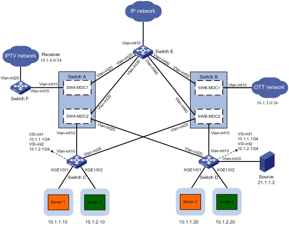
Table 1 Interface and IP address assignment
|
Device |
Interface |
IP address |
Device |
Interface |
IP address |
|
SWA-MDC1 |
Loopback0 |
6.6.6.6/32 |
Switch D |
Loopback0 |
4.4.4.4/32 |
|
|
Vlan-int10 |
17.1.1.6/24 |
|
Vlan-int10 |
14.1.1.4/24 |
|
|
Vlan-int20 |
18.1.1.6/24 |
|
Vlan-int20 |
13.1.1.4/24 |
|
SWA-MDC2 |
Loopback0 |
1.1.1.1/32 |
|
Vlan-int30 |
21.1.1.4/24 |
|
|
Vlan-int10 |
11.1.1.1/24 |
Switch E |
Loopback0 |
5.5.5.5/32 |
|
|
Vlan-int20 |
13.1.1.1/24 |
|
Vlan-int10 |
22.1.1.5/24 |
|
|
Vlan-int30 |
15.1.1.1/24 |
|
Vlan-int20 |
18.1.1.5/24 |
|
SWB-MDC1 |
Loopback0 |
7.7.7.7/32 |
|
Vlan-int30 |
15.1.1.5/24 |
|
|
Vlan-int10 |
19.1.1.7/24 |
|
Vlan-int40 |
16.1.1.5/24 |
|
|
Vlan-int50 |
20.1.1.7/24 |
|
Vlan-int50 |
19.1.1.5/24 |
|
SWB-MDC2 |
Loopback0 |
2.2.2.2/32 |
Switch F |
Loopback0 |
9.9.9.9/32 |
|
|
Vlan-int10 |
14.1.1.2/24 |
|
Vlan-int10 |
17.1.1.9/24 |
|
|
Vlan-int20 |
12.1.1.2/24 |
|
Vlan-int20 |
10.1.4.1/24 |
|
|
Vlan-int40 |
16.1.1.2/24 |
|
|
|
|
Switch C |
Loopback0 |
3.3.3.3/32 |
|
|
|
|
|
Vlan-int10 |
11.1.1.3/24 |
|
|
|
|
|
Vlan-int20 |
12.1.1.3/24 |
|
|
|
Analysis
To virtualize Switch A and Switch B into the required MDCs, configure MDCs on Switch A and Switch B.
For IP connectivity between SWA-MDC1, SWA-MDC2, SWB-MDC1, SWB-MDC2, Switch C, Switch D, and Switch E, configure a routing protocol on them and assign IP addresses to their interfaces, including loopback interfaces. In this example, OSPF is configured.
For Switch C and Switch D to use a VXLAN tunnel to communicate with each other, configure them as distributed EVPN gateways.
For the downlink ports of Switch C and Switch D to identify the VXLANs to which user network packets belong, configure Ethernet service instances and frame match criteria on the ports.
To enable SWA-MDC1, SWA-MDC2, SWB-MDC2, Switch D, and Switch E to establish a multicast distribution tree, configure PIM on them.
For the IPTV network and OTT network to access external networks, configure SWA-MDC1 as the IPTV network and configure SWB-MDC1 as the OTT network.
Software versions used
This configuration example was created and verified on S6860-CMW710-R2612 and S12500X-CMW710-R2710.
Restrictions and guidelines for MDC configuration
When you configure MDCs, follow these restrictions and guidelines:
· You can assign hardware resources to MDCs before or after you start the MDCs. As a best practice, assign MDCs resources before starting them.
· Before assigning an interface to or reclaiming an interface from an MDC, make sure no other users are configuring the interface.
· Interfaces on LPUs are grouped.
¡ The interfaces in a group must be assigned to or removed from the same MDC at the same time. Interface grouping varies by LPU model.
¡ Different groups of interfaces on an LPU can be assigned to different MDCs. You must assign the LPU to the MDCs.
· An interface can be assigned to only one MDC. An interface to be assigned to a non-default MDC must belong to the default MDC. To assign an interface that belongs to one non-default MDC to another non-default MDC, you must reclaim the interface first.
· To assign physical interfaces to an MDC, you must reclaim the LPUs where the physical interfaces reside from all MDCs. After assigning physical interfaces to an MDC, you must assign the LPUs where the physical interfaces reside to the MDC.
Restrictions and guidelines for EVPN configuration
When forwarding packets from ACs at Layer 3, EVPN gateways use the DSCP values in packets for priority mapping, regardless of whether the qos trust dscp command is configured on the incoming interfaces. When forwarding packets from ACs at Layer 2, EVPN gateways use the DSCP values in packets for priority mapping only if the qos trust dscp command is configured on the incoming interfaces.
Layer 3 interfaces (except VSI interfaces) on VTEPs and EVPN gateways cannot use a PBR policy to match VXLAN packets by outer layer source and destination IP addresses. To match VXLAN packets by outer layer source and destination IP addresses, apply a PBR policy on a VSI interface.
Make sure a VSI interface uses the same MAC address to provide service on distributed EVPN gateways connected to different sites.
When you configure a border device, follow these restrictions and guidelines:
· You cannot use the mac-address command to configure MAC addresses for Layer 3 Ethernet interfaces, Layer 3 aggregate interfaces, or their subinterfaces.
· If you apply an ACL to a Layer 3 Ethernet interface or Layer 3 aggregate interface to match packets, the ACL also matches packets on the subinterfaces.
· If you apply a QoS policy with no rules for inner or outer VLAN IDs to a Layer 3 Ethernet interface, the policy is also applied to the subinterfaces.
· If you apply a PBR policy to a Layer 3 Ethernet interface or Layer 3 aggregate interface, the policy is also applied to the subinterfaces.
· Broadcast, multicast, or unicast suppression settings configured on a Layer 3 Ethernet interface also take effect on the subinterfaces.
· A QoS policy rule does not match packets to be forwarded at Layer 3 that do not carry the specified VLAN IDs if the following conditions are met:
¡ You apply the QoS policy to an interface that is not a Layer 3 Ethernet interface.
¡ The rule matches inner or outer VLAN IDs.
· You cannot use the arp mode uni command to configure an interface on a border device as a customer-side port.
If both ARP flood suppression and local proxy ARP are enabled on a distributed EVPN gateway, only local proxy ARP takes effect. As a best practice, do not use these features together on distributed EVPN gateways.
For an EVPN gateway to perform Layer 3 forwarding, follow these guidelines for frame match criteria of Ethernet service instances:
· If the frame match criterion is encapsulation untagged, the access mode must be Ethernet. If not, the access mode must be VLAN.
· The frame match criterion cannot contain both inner and outer VLAN tags.
Procedures
Configuring MDCs on Switch A and Switch B
1. Configure SWA-MDC1 on Switch A:
# Create SWA-MDC1.
<SwitchA> system-view
[SwitchA] mdc SWA-MDC1
It will take some time to create MDC...
MDC created successfully.
[SwitchA-mdc-2-SWA-MDC1] quit
# Reclaim the LPUs in slot 1 and slot 2 from the default MDC.
[SwitchA] mdc Admin
[SwitchA-mdc-1-Admin] undo location slot 1
The configuration associated with the specified slot of MDC will be lost. Continue? [Y/N]:y
[SwitchA-mdc-1-Admin] undo location slot 2
The configuration associated with the specified slot of MDC will be lost. Continue? [Y/N]:y
[SwitchA-mdc-1-Admin] quit
# Assign interfaces Ten-GigabitEthernet 1/0/1 through Ten-GigabitEthernet 1/0/24 to SWA-MDC1.
[SwitchA] mdc SWA-MDC1
[SwitchA-mdc-2-SWA-MDC1] allocate interface ten-gigabitethernet 1/0/1 to ten-gigabitethernet 1/0/24
Configuration of the interfaces will be lost. Continue? [Y/N]:y
Execute the location slot command in this view to make the configuration take effect.
# Assign LPU 1 to SWA-MDC1.
[SwitchA-mdc-2-SWA-MDC1] location slot 1
# Start SWA-MDC1.
[SwitchA-mdc-2-SWA-MDC1] mdc start
It will take some time to start MDC...
MDC started successfully.
[SwitchA-mdc-2-SWA-MDC1] quit
2. Configure SWA-MDC2 on Switch A:
# Create SWA-MDC2.
[SwitchA] mdc SWA-MDC2
It will take some time to create MDC...
MDC created successfully.
# Assign interfaces Ten-GigabitEthernet 2/0/1 through Ten-GigabitEthernet 2/0/24 to SWA-MDC2.
[SwitchA-mdc-3-SWA-MDC2] allocate interface ten-gigabitethernet 2/0/1 to ten-gigabitethernet 2/0/24
Configuration of the interfaces will be lost. Continue? [Y/N]:y
Execute the location slot command in this view to make the configuration take effect.
# Assign LPU 2 to SWA-MDC2.
[SwitchA-mdc-3-SWA-MDC2] location slot 2
# Start SWA-MDC2.
[SwitchA-mdc-3-SWA-MDC2] mdc start
It will take some time to start MDC...
MDC started successfully.
[SwitchA-mdc-3-SWA-MDC2] quit
3. Configure SWB-MDC1 on Switch B:
# Create SWB-MDC1.
<SwitchB> system-view
[SwitchB] mdc SWB-MDC1
It will take some time to create MDC...
MDC created successfully.
[SwitchB-mdc-2-SWB-MDC1] quit
# Reclaim the LPUs in slot 1 and slot 2 from the default MDC.
[SwitchB] mdc Admin
[SwitchB-mdc-1-Admin] undo location slot 1
The configuration associated with the specified slot of MDC will be lost. Continue? [Y/N]:y
[SwitchB-mdc-1-Admin] undo location slot 2
The configuration associated with the specified slot of MDC will be lost. Continue? [Y/N]:y
[SwitchB-mdc-1-Admin] quit
# Assign interfaces Ten-GigabitEthernet 1/0/1 through Ten-GigabitEthernet 1/0/24 to SWB-MDC1.
[SwitchB] mdc SWA-MDC1
[SwitchB-mdc-2-SWB-MDC1] allocate interface ten-gigabitethernet 1/0/1 to ten-gigabitethernet 1/0/24
Configuration of the interfaces will be lost. Continue? [Y/N]:y
Execute the location slot command in this view to make the configuration take effect.
# Assign LPU 1 to SWB-MDC1.
[SwitchB-mdc-2-SWB-MDC1] location slot 1
# Start SWB-MDC1.
[SwitchB-mdc-2-SWB-MDC1] mdc start
It will take some time to start MDC...
MDC started successfully.
[SwitchB-mdc-2-SWB-MDC1] quit
4. Configure SWB-MDC2 on Switch B:
# Create SWB-MDC2.
[SwitchB] mdc SWB-MDC2
It will take some time to create MDC...
MDC created successfully.
# Assign interfaces Ten-GigabitEthernet 2/0/1 through Ten-GigabitEthernet 2/0/24 to SWB-MDC2.
[SwitchB-mdc-3-SWB-MDC2] allocate interface ten-gigabitethernet 2/0/1 to ten-gigabitethernet 2/0/24
Configuration of the interfaces will be lost. Continue? [Y/N]:y
Execute the location slot command in this view to make the configuration take effect.
# Assign LPU 2 to SWB-MDC2.
[SwitchB-mdc-3-SWB-MDC2] location slot 2
# Start SWB-MDC2.
[SwitchB-mdc-3-SWB-MDC2] mdc start
It will take some time to start MDC...
MDC started successfully.
[SwitchB-mdc-3-SWB-MDC2] quit
Configuring the IPTV and OTT networks
Assigning IP addresses to interfaces on the devices
# Log in to SWA-MDC1 and assign IP addresses to its interfaces.
[SwitchA] switchto mdc SWA-MDC1
******************************************************************************
* Copyright (c) 2004-2017 New H3C Technologies Co., Ltd. All rights reserved.*
* Without the owner's prior written consent, *
* no decompiling or reverse-engineering shall be allowed. *
******************************************************************************
Automatic configuration is running, press CTRL_D to break or press CTRL_B to
switch back to the default MDC.
<SWA-MDC1> system-view
[SWA-MDC1] interface loopback 0
[SWA-MDC1-Loopback0] ip address 6.6.6.6 32
[SWA-MDC1-Loopback0] quit
[SWA-MDC1] vlan 10
[SWA-MDC1-vlan10] port ten-gigabitethernet 1/0/1
[SWA-MDC1-vlan10] quit
[SWA-MDC1] interface vlan-interface 10
[SWA-MDC1-Vlan-interface10] ip address 17.1.1.6 24
[SWA-MDC1-Vlan-interface10] quit
[SWA-MDC1] vlan 20
[SWA-MDC1-vlan20] port ten-gigabitethernet 1/0/2
[SWA-MDC1-vlan20] quit
[SWA-MDC1] interface vlan-interface 20
[SWA-MDC1-Vlan-interface20] ip address 18.1.1.6 24
[SWA-MDC1-Vlan-interface20] quit
# Use the same method to log in to the other MDCs and assign IP addresses to interfaces. (Details not shown.)
# Assign IP addresses to interfaces on Switch C.
[SwitchC] interface loopback 0
[SwitchC-Loopback0] ip address 3.3.3.3 32
[SwitchC-Loopback0] quit
[SwitchC] vlan 10
[SwitchC-vlan10] port ten-gigabitethernet 1/0/3
[SwitchC-vlan10] quit
[SwitchC] interface vlan-interface 10
[SwitchC-Vlan-interface10] ip address 11.1.1.3 24
[SwitchC-Vlan-interface10] quit
[SwitchC] vlan 20
[SwitchC-vlan20] port ten-gigabitethernet 1/0/4
[SwitchC-vlan20] quit
[SwitchC] interface vlan-interface 20
[SwitchC-Vlan-interface20] ip address 12.1.1.3 24
[SwitchC-Vlan-interface20] quit
# Use the same method to assign IP addresses to interfaces on the other switches. (Details not shown.)
Configuring the routing protocol
# On SWA-MDC1, configure OSPF and advertise the route information about the networks connected to the interfaces.
[SWA-MDC1] ospf 100 router-id 6.6.6.6
[SWA-MDC1-ospf-100] area 0
[SWA-MDC1-ospf-100-area-0.0.0.0] network 6.6.6.6 0.0.0.0
[SWA-MDC1-ospf-100-area-0.0.0.0] network 17.1.1.0 0.0.0.255
[SWA-MDC1-ospf-100-area-0.0.0.0] network 18.1.1.0 0.0.0.255
[SWA-MDC1-ospf-100-area-0.0.0.0] quit
[SWA-MDC1-ospf-100] quit
# On SWA-MDC2, configure OSPF and advertise the route information about the networks connected to the interfaces.
[SWA-MDC2] ospf 100 router-id 1.1.1.1
[SWA-MDC2-ospf-100] area 0
[SWA-MDC2-ospf-100-area-0.0.0.0] network 1.1.1.1 0.0.0.0
[SWA-MDC2-ospf-100-area-0.0.0.0] network 11.1.1.0 0.0.0.255
[SWA-MDC2-ospf-100-area-0.0.0.0] network 13.1.1.0 0.0.0.255
[SWA-MDC2-ospf-100-area-0.0.0.0] network 15.1.1.0 0.0.0.255
[SWA-MDC2-ospf-100-area-0.0.0.0] quit
[SWA-MDC2-ospf-100] quit
# On SWB-MDC1, configure OSPF and advertise the route information about the networks connected to the interfaces.
[SWB-MDC1] ospf 100 router-id 7.7.7.7
[SWB-MDC1-ospf-100] area 0
[SWB-MDC1-ospf-100-area-0.0.0.0] network 7.7.7.7 0.0.0.0
[SWB-MDC1-ospf-100-area-0.0.0.0] network 19.1.1.0 0.0.0.255
[SWB-MDC1-ospf-100-area-0.0.0.0] network 20.1.1.0 0.0.0.255
[SWB-MDC1-ospf-100-area-0.0.0.0] quit
[SWB-MDC1-ospf-100] quit
# On SWB-MDC2, configure OSPF and advertise the route information about the networks connected to the interfaces.
[SWB-MDC2] ospf 100 router-id 2.2.2.2
[SWB-MDC2-ospf-100] area 0
[SWB-MDC2-ospf-100-area-0.0.0.0] network 2.2.2.2 0.0.0.0
[SWB-MDC2-ospf-100-area-0.0.0.0] network 12.1.1.0 0.0.0.255
[SWB-MDC2-ospf-100-area-0.0.0.0] network 14.1.1.0 0.0.0.255
[SWB-MDC2-ospf-100-area-0.0.0.0] network 16.1.1.0 0.0.0.255
[SWB-MDC2-ospf-100-area-0.0.0.0] quit
[SWB-MDC2-ospf-100] quit
# On Switch C, configure OSPF and advertise the route information about the networks connected to the interfaces.
[SwitchC] ospf 100 router-id 3.3.3.3
[SwitchC-ospf-100] area 0
[SwitchC-ospf-100-area-0.0.0.0] network 3.3.3.3 0.0.0.0
[SwitchC-ospf-100-area-0.0.0.0] network 11.1.1.0 0.0.0.255
[SwitchC-ospf-100-area-0.0.0.0] network 12.1.1.0 0.0.0.255
[SwitchC-ospf-100-area-0.0.0.0] quit
[SwitchC-ospf-100] quit
# On Switch D, configure OSPF and advertise the route information about the networks connected to the interfaces.
[SwitchD] ospf 100 router-id 4.4.4.4
[SwitchD-ospf-100] area 0
[SwitchD-ospf-100-area-0.0.0.0] network 4.4.4.4 0.0.0.0
[SwitchD-ospf-100-area-0.0.0.0] network 13.1.3.0 0.0.0.255
[SwitchD-ospf-100-area-0.0.0.0] network 14.1.1.0 0.0.0.255
[SwitchD-ospf-100-area-0.0.0.0] network 21.1.1.0 0.0.0.255
[SwitchD-ospf-100-area-0.0.0.0] quit
[SwitchD-ospf-100] quit
# On Switch E, configure OSPF and advertise the route information about the networks connected to the interfaces.
[SwitchE] ospf 100 router-id 5.5.5.5
[SwitchE-ospf-100] area 0
[SwitchE-ospf-100-area-0.0.0.0] network 5.5.5.5 0.0.0.0
[SwitchE-ospf-100-area-0.0.0.0] network 15.1.1.0 0.0.0.255
[SwitchE-ospf-100-area-0.0.0.0] network 16.1.1.0 0.0.0.255
[SwitchE-ospf-100-area-0.0.0.0] network 18.1.1.0 0.0.0.255
[SwitchE-ospf-100-area-0.0.0.0] network 19.1.1.0 0.0.0.255
[SwitchE-ospf-100-area-0.0.0.0] quit
[SwitchE-ospf-100] quit
# On Switch F, configure OSPF and advertise the route information about the networks connected to the interfaces.
[SwitchF] ospf 100 router-id 9.9.9.9
[SwitchF-ospf-100] area 0
[SwitchF-ospf-100-area-0.0.0.0] network 9.9.9.9 0.0.0.0
[SwitchF-ospf-100-area-0.0.0.0] network 17.1.1.0 0.0.0.255
[SwitchF-ospf-100-area-0.0.0.0] quit
[SwitchF-ospf-100] quit
Configuring the multicast protocol
1. Configure Switch D:
# Enable IP multicast routing and enable PIM-SM on VLAN-interface10, VLAN-interface 20, and VLAN-interface 30.
[SwitchD] multicast routing
[SwitchD-mrib] quit
[SwitchD] interface vlan-interface 10
[SwitchD-Vlan-interface10] pim sm
[SwitchD-Vlan-interface10] quit
[SwitchD] interface vlan-interface 20
[SwitchD-Vlan-interface20] pim sm
[SwitchD-Vlan-interface20] quit
[SwitchD] interface vlan-interface 30
[SwitchD-Vlan-interface30] pim sm
[SwitchD-Vlan-interface30] quit
# Configure Loopback 0 of SWB-MDC2 as the static RP.
[SwitchD] pim
[SwitchD-pim] static-rp 2.2.2.2
[SwitchD-pim] quit
2. Configure SWA-MDC2:
# Enable IP multicast routing and enable PIM-SM on VLAN-interface 20 and VLAN-interface 30.
<SWA-MDC2> system-view
[SWA-MDC2] multicast routing
[SWA-MDC2-mrib] quit
[SWA-MDC2] interface vlan-interface 20
[SWA-MDC2-Vlan-interface20] pim sm
[SWA-MDC2-Vlan-interface20] quit
[SWA-MDC2] interface vlan-interface 30
[SWA-MDC2-Vlan-interface30] pim sm
[SWA-MDC2-Vlan-interface30] quit
# Configure Loopback 0 of SWA-MDC2 as a C-BSR and C-RP, and configure Loopback 0 of SWB-MDC2 as the static RP.
[SWA-MDC2] pim
[SWA-MDC2-pim] c-bsr 1.1.1.1
[SWA-MDC2-pim] c-rp 1.1.1.1
[SWA-MDC2-pim] static-rp 2.2.2.2
[SWA-MDC2-pim] quit
3. Configure SWB-MDC2:
# Enable IP multicast routing and enable PIM-SM on VLAN-interface 10 and VLAN-interface 40.
<SWB-MDC2> system-view
[SWB-MDC2] multicast routing
[SWB-MDC2-mrib] quit
[SWB-MDC2] interface vlan-interface 10
[SWB-MDC2-Vlan-interface10] pim sm
[SWB-MDC2-Vlan-interface10] quit
[SWB-MDC2] interface vlan-interface 40
[SWB-MDC2-Vlan-interface40] pim sm
[SWB-MDC2-Vlan-interface40] quit
# Configure Loopback 0 of SWB-MDC2 as the static RP.
[SWB-MDC2] pim
[SWB-MDC2-pim] static-rp 2.2.2.2
[SWB-MDC2-pim] quit
4. Configure Switch E:
# Enable IP multicast routing and enable PIM-SM on VLAN-interface 20, VLAN-interface 30, and VLAN-interface 40.
[SwitchE] multicast routing
[SwitchE-mrib] quit
[SwitchE] interface vlan-interface 20
[SwitchE-Vlan-interface20] pim sm
[SwitchE-Vlan-interface20] quit
[SwitchE] interface vlan-interface 30
[SwitchE-Vlan-interface30] pim sm
[SwitchE-Vlan-interface30] quit
[SwitchE] interface vlan-interface 40
[SwitchE-Vlan-interface40] pim sm
[SwitchE-Vlan-interface40] quit
# Configure Loopback 0 of SWB-MDC2 as the static RP.
[SwitchE] pim
[SwitchE-pim] static-rp 2.2.2.2
[SwitchE-pim] quit
5. Configure SWA-MDC1:
# Enable IP multicast routing and enable PIM-SM on VLAN-interface 10 and VLAN-interface 20.
<SWA-MDC1> system-view
[SWA-MDC1] multicast routing
[SWA-MDC1-mrib] quit
[SWA-MDC1] interface vlan-interface 10
[SWA-MDC1-Vlan-interface10] pim sm
[SWA-MDC1-Vlan-interface10] quit
[SWA-MDC1] interface vlan-interface 20
[SWA-MDC1-Vlan-interface20] pim sm
[SWA-MDC1-Vlan-interface20] quit
# Configure Loopback 0 of SWB-MDC2 as the static RP.
[SWA-MDC1] pim
[SWA-MDC1-pim] static-rp 2.2.2.2
[SWA-MDC1-pim] quit
6. Configure Switch F:
# Enable IP multicast routing, enable IGMP on VLAN-interface 20 (the host-side interface), and enable PIM-SM on VLAN-interface 10.
[SwitchF] multicast routing
[SwitchF-mrib] quit
[SwitchF] interface vlan-interface 10
[SwitchF-Vlan-interface10] pim sm
[SwitchF-Vlan-interface10] quit
[SwitchF] interface vlan-interface 20
[SwitchF-Vlan-interface20] igmp enable
[SwitchF-Vlan-interface20] quit
# Configure Loopback 0 of SWB-MDC2 as the static RP.
[SwitchF] pim
[SwitchF-pim] static-rp 2.2.2.2
[SwitchF-pim] quit
Configuring the EVPN network
Creating VSIs, EVPN instances, and VXLANs
1. Configure Switch C:
# Enable L2VPN.
[SwitchC] l2vpn enable
# Set the VXLAN hardware resource mode. (For the VXLAN hardware resource mode to take effect, you must reboot the switch. This example does not provide the steps for rebooting the switch.)
[SwitchC] hardware-resource vxlan l3gw8k
# Disable remote MAC address learning and remote ARP learning.
[SwitchC] vxlan tunnel mac-learning disable
[SwitchC] vxlan tunnel arp-learning disable
# Create an EVPN instance on VSI vpna, and configure the switch to automatically generate an RD and a route target for the EVPN instance.
[SwitchC] vsi vpna
[SwitchC-vsi-vpna] evpn encapsulation vxlan
[SwitchC-vsi-vpna-evpn-vxlan] route-distinguisher auto
[SwitchC-vsi-vpna-evpn-vxlan] vpn-target auto
[SwitchC-vsi-vpna-evpn-vxlan] quit
# Create VXLAN 10.
[SwitchC-vsi-vpna] vxlan 10
[SwitchC-vsi-vpna-vxlan-10] quit
[SwitchC-vsi-vpna] quit
# Create an EVPN instance on VSI vpnb, and configure the switch to automatically generate an RD and a route target for the EVPN instance.
[SwitchC] vsi vpnb
[SwitchC-vsi-vpnb] evpn encapsulation vxlan
[SwitchC-vsi-vpnb-evpn-vxlan] route-distinguisher auto
[SwitchC-vsi-vpnb-evpn-vxlan] vpn-target auto
[SwitchC-vsi-vpnb-evpn-vxlan] quit
# Create VXLAN 20.
[SwitchC-vsi-vpnb] vxlan 20
[SwitchC-vsi-vpnb-vxlan-20] quit
[SwitchC-vsi-vpnb] quit
2. Configure Switch D:
# Enable L2VPN.
[SwitchD] l2vpn enable
# Set the VXLAN hardware resource mode. (For the VXLAN hardware resource mode to take effect, you must reboot the switch. This example does not provide the steps for rebooting the switch.)
[SwitchD] hardware-resource vxlan l3gw8k
# Disable remote MAC address learning and remote ARP learning.
[SwitchD] vxlan tunnel mac-learning disable
[SwitchD] vxlan tunnel arp-learning disable
# Create an EVPN instance on VSI vpna, and configure the switch to automatically generate an RD and a route target for the EVPN instance.
[SwitchD] vsi vpna
[SwitchD-vsi-vpna] evpn encapsulation vxlan
[SwitchD-vsi-vpna-evpn-vxlan] route-distinguisher auto
[SwitchD-vsi-vpna-evpn-vxlan] vpn-target auto
[SwitchD-vsi-vpna-evpn-vxlan] quit
# Create VXLAN 10.
[SwitchD-vsi-vpna] vxlan 10
[SwitchD-vsi-vpna-vxlan-10] quit
[SwitchD-vsi-vpna] quit
# Create an EVPN instance on VSI vpnb, and configure the switch to automatically generate an RD and a route target for the EVPN instance.
[SwitchD] vsi vpnb
[SwitchD-vsi-vpnb] evpn encapsulation vxlan
[SwitchD-vsi-vpnb-evpn-vxlan] route-distinguisher auto
[SwitchD-vsi-vpnb-evpn-vxlan] vpn-target auto
[SwitchD-vsi-vpnb-evpn-vxlan] quit
# Create VXLAN 20.
[SwitchD-vsi-vpnb] vxlan 20
[SwitchD-vsi-vpnb-vxlan-20] quit
[SwitchD-vsi-vpnb] quit
Configuring Ethernet service instances to match packets and mapping the instances to VSIs
1. Configure Switch C:
# On Ten-GigabitEthernet 1/0/1, create Ethernet service instance 1000 to match VLAN 10 (Server 1), and map the Ethernet service instance to VSI vpna (VXLAN 10).
[SwitchC] interface ten-gigabitethernet 1/0/1
[SwitchC-Ten-GigabitEthernet1/0/1] service-instance 1000
[SwitchC-Ten-GigabitEthernet1/0/1-srv1000] encapsulation s-vid 10
[SwitchC-Ten-GigabitEthernet1/0/1-srv1000] xconnect vsi vpna
[SwitchC-Ten-GigabitEthernet1/0/1-srv1000] quit
[SwitchC-Ten-GigabitEthernet1/0/1] quit
# On Ten-GigabitEthernet 1/0/2, create Ethernet service instance 1000 to match VLAN 11 (Server 2), and map the Ethernet service instance to VSI vpnb (VXLAN 20).
[SwitchC] interface ten-gigabitethernet 1/0/2
[SwitchC-Ten-GigabitEthernet1/0/2] service-instance 1000
[SwitchC-Ten-GigabitEthernet1/0/2-srv1000] encapsulation s-vid 11
[SwitchC-Ten-GigabitEthernet1/0/2-srv1000] xconnect vsi vpnb
[SwitchC-Ten-GigabitEthernet1/0/2-srv1000] quit
[SwitchC-Ten-GigabitEthernet1/0/2] quit
2. Configure Switch D:
# On Ten-GigabitEthernet 1/0/1, create Ethernet service instance 1000 to match VLAN 12 (Server 3), and map the Ethernet service instance to VSI vpna (VXLAN 10).
[SwitchD] interface ten-gigabitethernet 1/0/1
[SwitchD-Ten-GigabitEthernet1/0/1] service-instance 1000
[SwitchD-Ten-GigabitEthernet1/0/1-srv1000] encapsulation s-vid 12
[SwitchD-Ten-GigabitEthernet1/0/1-srv1000] xconnect vsi vpna
[SwitchD-Ten-GigabitEthernet1/0/1-srv1000] quit
[SwitchD-Ten-GigabitEthernet1/0/1] quit
# On Ten-GigabitEthernet 1/0/2, create Ethernet service instance 1000 to match VLAN 13 (Server 4), and map the Ethernet service instance to VSI vpnb (VXLAN 20).
[SwitchD] interface ten-gigabitethernet 1/0/2
[SwitchD-Ten-GigabitEthernet1/0/2] service-instance 1000
[SwitchD-Ten-GigabitEthernet1/0/2-srv1000] encapsulation s-vid 13
[SwitchD-Ten-GigabitEthernet1/0/2-srv1000] xconnect vsi vpnb
[SwitchD-Ten-GigabitEthernet1/0/2-srv1000] quit
[SwitchD-Ten-GigabitEthernet1/0/2] quit
Configuring BGP to advertise BGP EVPN routes
1. Configure SWA-MDC2:
# Configure SWA-MDC2 to establish BGP connections to other devices.
<SWA-MDC2> system-view
[SWA-MDC2] bgp 100
[SWA-MDC2-bgp-default] group evpn
[SWA-MDC2-bgp-default] peer 3.3.3.3 group evpn
[SWA-MDC2-bgp-default] peer 4.4.4.4 group evpn
[SWA-MDC2-bgp-default] peer 5.5.5.5 group evpn
[SWA-MDC2-bgp-default] peer evpn as-number 100
[SWA-MDC2-bgp-default] peer evpn connect-interface loopback 0
[SWA-MDC2-bgp-default] peer 2.2.2.2 as-number 100
[SWA-MDC2-bgp-default] peer 2.2.2.2 connect-interface loopback 0
# Configure BGP to advertise BGP EVPN routes, and disable route target filtering for BGP EVPN routes.
[SWA-MDC2-bgp-default] address-family l2vpn evpn
[SWA-MDC2-bgp-default-evpn] peer evpn enable
[SWA-MDC2-bgp-default-evpn] peer 2.2.2.2 enable
[SWA-MDC2-bgp-default-evpn] undo policy vpn-target
# Configure SWA-MDC2 as the RR.
[SWA-MDC2-bgp-default-evpn] reflector cluster-id 8.8.8.8
[SWA-MDC2-bgp-default-evpn] peer evpn reflect-client
[SWA-MDC2-bgp-default-evpn] quit
[SWA-MDC2-bgp-default] quit
2. Configure SWB-MDC2:
# Configure SWB-MDC2 to establish BGP connections to other devices.
<SWB-MDC2> system-view
[SWB-MDC2] bgp 100
[SWB-MDC2-bgp-default] group evpn
[SWB-MDC2-bgp-default] peer 3.3.3.3 group evpn
[SWB-MDC2-bgp-default] peer 4.4.4.4 group evpn
[SWB-MDC2-bgp-default] peer 5.5.5.5 group evpn
[SWB-MDC2-bgp-default] peer evpn as-number 100
[SWB-MDC2-bgp-default] peer evpn connect-interface loopback 0
[SWB-MDC2-bgp-default] peer 1.1.1.1 as-number 100
[SWB-MDC2-bgp-default] peer 1.1.1.1 connect-interface loopback 0
# Configure BGP to advertise BGP EVPN routes, and disable route target filtering for BGP EVPN routes.
[SWB-MDC2-bgp-default] address-family l2vpn evpn
[SWB-MDC2-bgp-default-evpn] peer evpn enable
[SWB-MDC2-bgp-default-evpn] peer 1.1.1.1 enable
[SWB-MDC2-bgp-default-evpn] undo policy vpn-target
# Configure SWB-MDC2 as the RR.
[SWB-MDC2-bgp-default-evpn] reflector cluster-id 8.8.8.8
[SWB-MDC2-bgp-default-evpn] peer evpn reflect-client
[SWB-MDC2-bgp-default-evpn] quit
[SWB-MDC2-bgp-default] quit
3. Configure Switch C:
# Configure Switch C to establish BGP connections to other devices.
[SwitchC] bgp 100
[SwitchC-bgp-default] peer 1.1.1.1 as-number 100
[SwitchC-bgp-default] peer 1.1.1.1 connect-interface loopback 0
[SwitchC-bgp-default] peer 2.2.2.2 as-number 100
[SwitchC-bgp-default] peer 2.2.2.2 connect-interface loopback 0
# Configure BGP to advertise BGP EVPN routes.
[SwitchC-bgp-default] address-family l2vpn evpn
[SwitchC-bgp-default-evpn] peer 1.1.1.1 enable
[SwitchC-bgp-default-evpn] peer 2.2.2.2 enable
4. Configure Switch D:
# Configure Switch D to establish BGP connections to other devices.
[SwitchD] bgp 100
[SwitchD-bgp-default] peer 1.1.1.1 as-number 100
[SwitchD-bgp-default] peer 1.1.1.1 connect-interface loopback 0
[SwitchD-bgp-default] peer 2.2.2.2 as-number 100
[SwitchD-bgp-default] peer 2.2.2.2 connect-interface loopback 0
# Configure BGP to advertise BGP EVPN routes.
[SwitchD-bgp-default] address-family l2vpn evpn
[SwitchD-bgp-default-evpn] peer 1.1.1.1 enable
[SwitchD-bgp-default-evpn] peer 2.2.2.2 enable
5. Configure Switch E:
# Configure Switch E to establish BGP connections to other devices.
[SwitchE] bgp 100
[SwitchE-bgp-default] peer 1.1.1.1 as-number 100
[SwitchE-bgp-default] peer 1.1.1.1 connect-interface loopback 0
[SwitchE-bgp-default] peer 2.2.2.2 as-number 100
[SwitchE-bgp-default] peer 2.2.2.2 connect-interface loopback 0
# Configure BGP to advertise BGP EVPN routes.
[SwitchE-bgp-default] address-family l2vpn evpn
[SwitchE-bgp-default-evpn] peer 1.1.1.1 enable
[SwitchE-bgp-default-evpn] peer 2.2.2.2 enable
Configuring the distributed EVPN gateways
1. Configure Switch C:
# Configure RD and route target settings for VPN instance vpna.
[SwitchC] ip vpn-instance vpna
[SwitchC-vpn-instance-vpna] route-distinguisher 1:1
[SwitchC-vpn-instance-vpna] address-family ipv4
[SwitchC-vpn-ipv4-vpna] vpn-target 2:2
[SwitchC-vpn-ipv4-vpna] quit
[SwitchC-vpn-instance-vpna] address-family evpn
[SwitchC-vpn-evpn-vpna] vpn-target 1:1
[SwitchC-vpn-evpn-vpna] quit
[SwitchC-vpn-instance-vpna] quit
# Configure VSI-interface 1.
[SwitchC] interface vsi-interface 1
[SwitchC-Vsi-interface1] ip binding vpn-instance vpna
[SwitchC-Vsi-interface1] ip address 10.1.1.1 255.255.255.0
[SwitchC-Vsi-interface1] mac-address 1-1-1
[SwitchC-Vsi-interface1] distributed-gateway local
[SwitchC-Vsi-interface1] local-proxy-arp enable
[SwitchC-Vsi-interface1] quit
# Configure VSI-interface 2.
[SwitchC] interface vsi-interface 2
[SwitchC-Vsi-interface2] ip binding vpn-instance vpna
[SwitchC-Vsi-interface2] ip address 10.1.2.1 255.255.255.0
[SwitchC-Vsi-interface2] mac-address 2-2-2
[SwitchC-Vsi-interface2] distributed-gateway local
[SwitchC-Vsi-interface2] local-proxy-arp enable
[SwitchC-Vsi-interface2] quit
# Create VSI-interface 3. Associate VSI-interface 3 with VPN instance vpna, and configure the L3 VXLAN ID as 1000 for the VPN instance.
[SwitchC] interface vsi-interface 3
[SwitchC-Vsi-interface3] ip binding vpn-instance vpna
[SwitchC-Vsi-interface3] l3-vni 1000
[SwitchC-Vsi-interface3] quit
# Specify VSI-interface 1 as the gateway interface for VSI vpna (the VSI of VXLAN 10).
[SwitchC] vsi vpna
[SwitchC-vsi-vpna] gateway vsi-interface 1
[SwitchC-vsi-vpna] quit
# Specify VSI-interface 2 as the gateway interface for VSI vpnb (the VSI of VXLAN 20).
[SwitchC] vsi vpnb
[SwitchC-vsi-vpnb] gateway vsi-interface 2
[SwitchC-vsi-vpnb] quit
2. Configure Switch D:
# Configure RD and route target settings for VPN instance vpna.
[SwitchD] ip vpn-instance vpna
[SwitchD-vpn-instance-vpna] route-distinguisher 1:1
[SwitchD-vpn-instance-vpna] address-family ipv4
[SwitchD-vpn-ipv4-vpna] vpn-target 2:2
[SwitchD-vpn-ipv4-vpna] quit
[SwitchD-vpn-instance-vpna] address-family evpn
[SwitchD-vpn-evpn-vpna] vpn-target 1:1
[SwitchD-vpn-evpn-vpna] quit
[SwitchD-vpn-instance-vpna] quit
# Configure VSI-interface 1.
[SwitchD] interface vsi-interface 1
[SwitchD-Vsi-interface1] ip binding vpn-instance vpna
[SwitchD-Vsi-interface1] ip address 10.1.1.1 255.255.255.0
[SwitchD-Vsi-interface1] mac-address 1-1-1
[SwitchD-Vsi-interface1] distributed-gateway local
[SwitchD-Vsi-interface1] local-proxy-arp enable
[SwitchD-Vsi-interface1] quit
# Configure VSI-interface 2.
[SwitchD] interface vsi-interface 2
[SwitchD-Vsi-interface2] ip binding vpn-instance vpna
[SwitchD-Vsi-interface2] ip address 10.1.2.1 255.255.255.0
[SwitchD-Vsi-interface2] mac-address 2-2-2
[SwitchD-Vsi-interface2] distributed-gateway local
[SwitchD-Vsi-interface2] local-proxy-arp enable
[SwitchD-Vsi-interface2] quit
# Create VSI-interface 3. Associate VSI-interface 3 with VPN instance vpna, and configure the L3 VXLAN ID as 1000 for the VPN instance.
[SwitchD] interface vsi-interface 3
[SwitchD-Vsi-interface3] ip binding vpn-instance vpna
[SwitchD-Vsi-interface3] l3-vni 1000
[SwitchD-Vsi-interface3] quit
# Specify VSI-interface 1 as the gateway interface for VSI vpna (the VSI of VXLAN 10).
[SwitchD] vsi vpna
[SwitchD-vsi-vpna] gateway vsi-interface 1
[SwitchD-vsi-vpna] quit
# Specify VSI-interface 2 as the gateway interface for VSI vpnb (the VSI of VXLAN 20).
[SwitchD] vsi vpnb
[SwitchD-vsi-vpnb] gateway vsi-interface 2
[SwitchD-vsi-vpnb] quit
Configuring border gateway Switch E
# Enable L2VPN.
<SwitchE> system-view
[SwitchE] l2vpn enable
# Set the VXLAN hardware resource mode. (For the VXLAN hardware resource mode to take effect, you must reboot the switch. This example does not provide the steps for rebooting the switch.)
[SwitchE] hardware-resource vxlan border24k
# Disable remote MAC address learning and remote ARP learning.
[SwitchE] vxlan tunnel mac-learning disable
[SwitchE] vxlan tunnel arp-learning disable
# Configure RD and route target settings for VPN instance vpna.
[SwitchE] ip vpn-instance vpna
[SwitchE-vpn-instance-vpna] route-distinguisher 1:1
[SwitchE-vpn-instance-vpna] address-family ipv4
[SwitchE-vpn-ipv4-vpna] vpn-target 2:2
[SwitchE-vpn-ipv4-vpna] quit
[SwitchE-vpn-instance-vpna] address-family evpn
[SwitchE-vpn-evpn-vpna] vpn-target 1:1
[SwitchE-vpn-evpn-vpna] quit
[SwitchE-vpn-instance-vpna] quit
# Create VSI-interface 3. Associate VSI-interface 3 with VPN instance vpna, and configure the L3 VXLAN ID as 1000 for the VPN instance.
[SwitchE] interface vsi-interface 3
[SwitchE-Vsi-interface3] ip binding vpn-instance vpna
[SwitchE-Vsi-interface3] l3-vni 1000
[SwitchE-Vsi-interface3] quit
# Configure a default route. Set the next hop to 22.1.1.100 (the IP address of a device in the Internet).
[SwitchE] ip route-static vpn-instance vpna 0.0.0.0 0 22.1.1.100
# Redistribute the default route to the BGP IPv4 unicast routing table of VPN instance vpna.
[SwitchE] bgp 100
[SwitchE-bgp-default] ip vpn-instance vpna
[SwitchE-bgp-default-vpna] address-family ipv4 unicast
[SwitchE-bgp-default-ipv4-vpna] default-route imported
[SwitchE-bgp-default-ipv4-vpna] import-route static
[SwitchE-bgp-default-ipv4-vpna] quit
[SwitchE-bgp-default-vpna] quit
[SwitchE-bgp-default] quit
# Associate VLAN-interface 10 (the interface connected to the Internet) with VPN instance vpna.
[SwitchE] interface vlan-interface 10
[SwitchE-Vlan-interface20] ip binding vpn-instance vpna
[SwitchE-Vlan-interface20] ip address 22.1.1.5 24
[SwitchE-Vlan-interface20] quit
Verifying the configuration
Verifying the MDC configuration
# Verify that the MDCs on Switch A exist and are operating correctly.
[SwitchA] display mdc
ID Name Status
1 Admin active
2 SWA-MDC1 active
3 SWA-MDC2 active
The output shows that the MDCs have been created and are operating correctly.
# Log in to SWA-MDC2.
[SwitchA] switchto mdc SWA-MDC2
******************************************************************************
* Copyright (c) 2004-2018 New H3C Technologies Co., Ltd. All rights reserved.*
* Without the owner's prior written consent, *
* no decompiling or reverse-engineering shall be allowed. *
******************************************************************************
<SWA-MDC2>%Mar 2 10:43:04:214 2018 SWA-MDC2 SHELL/5/SHELL_LOGIN: -MDC=3; Console logged in from con0.
# Display the interfaces assigned to SWA-MDC2.
<SWA-MDC2> display interface brief
Brief information on interfaces in route mode:
Link: ADM - administratively down; Stby - standby
Protocol: (s) - spoofing
Interface Link Protocol Primary IP Description
InLoop0 UP UP(s) --
Loop0 UP UP(s) 1.1.1.1
MGE0/0/0 DOWN DOWN --
NULL0 UP UP(s) --
REG0 UP -- --
Vlan10 UP UP 11.1.1.1
Vlan20 UP UP 13.1.1.1
Vlan30 UP UP 15.1.1.1
Brief information on interfaces in bridge mode:
Link: ADM - administratively down; Stby - standby
Speed: (a) - auto
Duplex: (a)/A - auto; H - half; F - full
Type: A - access; T - trunk; H - hybrid
Interface Link Speed Duplex Type PVID Description
XGE2/0/1 UP 1G(a) F A 30
XGE2/0/2 ADM auto F A 1
XGE2/0/3 UP 1G(a) F A 10
XGE2/0/4 UP 1G(a) F A 20
XGE2/0/5 ADM auto F A 1
XGE2/0/6 ADM auto F A 1
XGE2/0/7 ADM auto F A 1
XGE2/0/8 ADM auto F A 1
XGE2/0/9 ADM auto F A 1
XGE2/0/10 ADM auto F A 1
XGE2/0/11 ADM auto F A 1
XGE2/0/12 ADM auto F A 1
XGE2/0/13 ADM auto F A 1
XGE2/0/14 ADM auto F A 1
XGE2/0/15 ADM auto F A 1
XGE2/0/16 ADM auto F A 1
XGE2/0/17 ADM auto F A 1
XGE2/0/18 ADM auto F A 1
XGE2/0/19 ADM auto F A 1
XGE2/0/20 ADM auto F A 1
XGE2/0/21 ADM auto F A 1
XGE2/0/22 ADM auto F A 1
XGE2/0/23 ADM auto F A 1
XGE2/0/24 ADM auto F A 1
# Use the same method to verify the MDC configuration on Switch B. (Details not shown.)
Verifying the EVPN network
# Display EVPN routing information on distributed EVPN gateway Switch C.
[SwitchC] display bgp l2vpn evpn
BGP local router ID is 3.3.3.3
Status codes: * - valid, > - best, d - dampened, h - history
s - suppressed, S - stale, i - internal, e - external
a - additional-path
Origin: i - IGP, e - EGP, ? - incomplete
Total number of routes from all PEs: 10
Route distinguisher: 1:1(vpna)
Total number of routes: 6
Network NextHop MED LocPrf PrefVal Path/Ogn
* >i [2][0][48][a21a-36c9-0806][32][10.1.1.20]/136
4.4.4.4 0 100 0 i
* >i [2][0][48][a21a-39de-0907][32][10.1.2.20]/136
4.4.4.4 0 100 0 i
* >i [5][0][0][0.0.0.0]/80
5.5.5.5 0 100 0 ?
* i 5.5.5.5 0 100 0 ?
* > [5][0][24][10.1.1.0]/80
0.0.0.0 0 100 32768 i
* > [5][0][24][10.1.2.0]/80
0.0.0.0 0 100 32768 i
Route distinguisher: 1:10
Total number of routes: 6
Network NextHop MED LocPrf PrefVal Path/Ogn
* > [2][0][48][a21a-2df1-0606][32][10.1.1.10]/136
0.0.0.0 0 100 32768 i
* >i [2][0][48][a21a-36c9-0806][32][10.1.1.20]/136
4.4.4.4 0 100 0 i
* i 4.4.4.4 0 100 0 i
* > [3][0][32][3.3.3.3]/80
0.0.0.0 0 100 32768 i
* >i [3][0][32][4.4.4.4]/80
4.4.4.4 0 100 0 i
* i 4.4.4.4 0 100 0 i
Route distinguisher: 1:20
Total number of routes: 6
Network NextHop MED LocPrf PrefVal Path/Ogn
* > [2][0][48][a21a-3300-0707][32][10.1.2.10]/136
0.0.0.0 0 100 32768 i
* >i [2][0][48][a21a-39de-0907][32][10.1.2.20]/136
4.4.4.4 0 100 0 i
* i 4.4.4.4 0 100 0 i
* > [3][0][32][3.3.3.3]/80
0.0.0.0 0 100 32768 i
* >i [3][0][32][4.4.4.4]/80
4.4.4.4 0 100 0 i
* i 4.4.4.4 0 100 0 i
# Verify that the VXLAN tunnel interfaces are up.
[SwitchC] display interface tunnel
Tunnel0
Current state: UP
Line protocol state: UP
Description: Tunnel0 Interface
Bandwidth: 64 kbps
Maximum transmission unit: 1464
Internet protocol processing: Disabled
Last clearing of counters: Never
Tunnel source 3.3.3.3, destination 4.4.4.4
Tunnel protocol/transport UDP_VXLAN/IP
Last 300 seconds input rate: 0 bytes/sec, 0 bits/sec, 0 packets/sec
Last 300 seconds output rate: 0 bytes/sec, 0 bits/sec, 0 packets/sec
Input: 10 packets, 980 bytes, 0 drops
Output: 19 packets, 1520 bytes, 0 drops
Tunnel1
Current state: UP
Line protocol state: UP
Description: Tunnel1 Interface
Bandwidth: 64 kbps
Maximum transmission unit: 1464
Internet protocol processing: Disabled
Last clearing of counters: Never
Tunnel source 3.3.3.3, destination 5.5.5.5
Tunnel protocol/transport UDP_VXLAN/IP
Last 300 seconds input rate: 0 bytes/sec, 0 bits/sec, 0 packets/sec
Last 300 seconds output rate: 0 bytes/sec, 0 bits/sec, 0 packets/sec
Input: 0 packets, 0 bytes, 0 drops
Output: 0 packets, 0 bytes, 0 drops
# Verify that the VSI interfaces are up on Switch C.
[SwitchC] display interface vsi-interface
Vsi-interface1
Current state: UP
Line protocol state: UP
Description: Vsi-interface1 Interface
Bandwidth: 1000000 kbps
Maximum transmission unit: 1444
Internet address: 10.1.1.1/24 (primary)
IP packet frame type: Ethernet II, hardware address: 0001-0001-0001
IPv6 packet frame type: Ethernet II, hardware address: 0001-0001-0001
Physical: Unknown, baudrate: 1000000 kbps
Last clearing of counters: Never
Input (total): 0 packets, 0 bytes
Output (total): 0 packets, 0 bytes
Vsi-interface2
Current state: UP
Line protocol state: UP
Description: Vsi-interface2 Interface
Bandwidth: 1000000 kbps
Maximum transmission unit: 1444
Internet address: 10.1.2.1/24 (primary)
IP packet frame type: Ethernet II, hardware address: 0002-0002-0002
IPv6 packet frame type: Ethernet II, hardware address: 0002-0002-0002
Physical: Unknown, baudrate: 1000000 kbps
Last clearing of counters: Never
Input (total): 0 packets, 0 bytes
Output (total): 0 packets, 0 bytes
Vsi-interface3
Current state: UP
Line protocol state: UP
Description: Vsi-interface3 Interface
Bandwidth: 1000000 kbps
Maximum transmission unit: 1444
Internet protocol processing: Disabled
IP packet frame type: Ethernet II, hardware address: a21a-0861-0300
IPv6 packet frame type: Ethernet II, hardware address: a21a-0861-0300
Physical: Unknown, baudrate: 1000000 kbps
Last clearing of counters: Never
Input (total): 0 packets, 0 bytes
Output (total): 0 packets, 0 bytes
# Verify that the VXLAN tunnels have been assigned to the VXLANs, and the VSI interfaces are the gateway interfaces of their respective VXLANs.
[SwitchC] display l2vpn vsi verbose
VSI Name: Auto_L3VNI1000_3
VSI Index : 2
VSI State : Down
MTU : 1500
Bandwidth : Unlimited
Broadcast Restrain : Unlimited
Multicast Restrain : Unlimited
Unknown Unicast Restrain: Unlimited
MAC Learning : Enabled
MAC Table Limit : -
MAC Learning rate : -
Drop Unknown : -
Flooding : Enabled
Statistics : Disabled
Gateway Interface : VSI-interface 3
VXLAN ID : 1000
VSI Name: vpna
VSI Index : 0
VSI State : Up
MTU : 1500
Bandwidth : Unlimited
Broadcast Restrain : Unlimited
Multicast Restrain : Unlimited
Unknown Unicast Restrain: Unlimited
MAC Learning : Enabled
MAC Table Limit : -
MAC Learning rate : -
Drop Unknown : -
Flooding : Enabled
Statistics : Disabled
Gateway Interface : VSI-interface 1
VXLAN ID : 10
Tunnels:
Tunnel Name Link ID State Type Flood proxy
Tunnel0 0x5000000 UP Auto Disabled
ACs:
AC Link ID State Type
XGE1/0/1 srv1000 0 Up Manual
VSI Name: vpnb
VSI Index : 1
VSI State : Up
MTU : 1500
Bandwidth : Unlimited
Broadcast Restrain : Unlimited
Multicast Restrain : Unlimited
Unknown Unicast Restrain: Unlimited
MAC Learning : Enabled
MAC Table Limit : -
MAC Learning rate : -
Drop Unknown : -
Flooding : Enabled
Statistics : Disabled
Gateway Interface : VSI-interface 2
VXLAN ID : 20
Tunnels:
Tunnel Name Link ID State Type Flood proxy
Tunnel0 0x5000000 UP Auto Disabled
ACs:
AC Link ID State Type
XGE1/0/2 srv1000 0 Up Manual
# Verify that Switch C has created ARP entries for the VMs.
[SwitchC] display arp
Type: S-Static D-Dynamic O-Openflow R-Rule M-Multiport I-Invalid
IP address MAC address VLAN/VSI Interface Aging Type
11.1.1.1 a210-9a1c-0182 10 XGE1/0/3 240 D
12.1.1.2 a21a-01b9-0242 20 XGE1/0/5 240 D
10.1.1.10 a21a-2df1-0606 0 XGE1/0/1 489 D
10.1.2.10 a21a-3300-0707 1 XGE1/0/2 414 D
4.4.4.4 a21a-0fb2-0400 2 Tunnel0 -- R
5.5.5.5 a21a-17fd-0500 2 Tunnel1 -- R
# Verify that Switch C has created EVPN ARP entries for the local VMs.
[SwitchC] display evpn route arp
Flags: D - Dynamic B - BGP L - Local active
G - Gateway S - Static M - Mapping
VPN instance: vpna Interface: Vsi-interface1
IP address MAC address Router MAC VSI index Flags
10.1.1.1 0001-0001-0001 a21a-0861-0300 0 GL
10.1.1.10 a21a-2df1-0606 a21a-0861-0300 0 DL
10.1.1.20 a21a-36c9-0806 a21a-0fb2-0400 0 B
VPN instance: vpna Interface: Vsi-interface2
IP address MAC address Router MAC VSI index Flags
10.1.2.1 0002-0002-0002 a21a-0861-0300 1 GL
10.1.2.10 a21a-3300-0707 a21a-0861-0300 1 DL
10.1.2.20 a21a-39de-0907 a21a-0fb2-0400 1 B
<SwitchC>
# Verify that the servers can communicate with one another and can communicate with the Internet. (Details not shown.)
Verifying the multicast network
# On Switch F, display RP information in the PIM-SM domain.
[SwitchF] display pim rp-info
BSR RP information:
Scope: non-scoped
Group/MaskLen: 225.1.1.0/24
RP address Priority HoldTime Uptime Expires
1.1.1.1 192 180 00:51:45 00:02:22
Static RP information:
RP address ACL Mode Preferred
2.2.2.2 ---- pim-sm No
[SwitchF] display pim bsr-info
Scope: non-scoped
State: Accept Preferred
Bootstrap timer: 00:01:44
Elected BSR address: 1.1.1.1
Priority: 64
Hash mask length: 30
Uptime: 00:11:18
[SwitchF]disp pim interface
Interface NbrCnt HelloInt DR-Pri DR-Address
Vlan10 0 30 1 10.1.4.1 (local)
Vlan20 1 30 1 1.1.1.1
# On SWA-MDC2, display BSR information in the PIM-SM domain.
[SWA-MDC2] display pim bsr-info
Scope: non-scoped
State: Elected
Bootstrap timer: 00:01:44
Elected BSR address: 1.1.1.1
Priority: 64
Hash mask length: 30
Uptime: 00:11:18
Candidate BSR address: 1.1.1.1
Priority: 64
Hash mask length: 30
# On SWA-MDC2, display C-RP information in the PIM-SM domain.
[SWA-MDC2] display pim c-rp
Scope: non-scoped
Group/MaskLen: 224.0.0.0/4
C-RP address Priority HoldTime Uptime Expires
1.1.1.1 (local) 192 150 03:01:36 00:02:29
Configuration files
· Switch A:
#
mdc SWA-MDC1 id 2
mdc start
allocate interface Ten-GigabitEthernet1/0/1 to Ten-GigabitEthernet 1/0/24
#
mdc SWA-MDC2 id 3
mdc start
allocate interface Ten-GigabitEthernet 2/0/1 to Ten-GigabitEthernet 2/0/24
#
· SWA-MDC1:
#
ospf 100 router-id 6.6.6.6
area 0.0.0.0
network 6.6.6.6 0.0.0.0
network 17.1.1.0 0.0.0.255
network 18.1.1.0 0.0.0.255
#
vlan 10
#
vlan 20
#
interface LoopBack0
ip address 6.6.6.6 255.255.255.255
#
interface Vlan-interface10
ip address 17.1.1.6 255.255.255.0
pim sm
#
interface Vlan-interface20
ip address 18.1.1.6 255.255.255.0
pim sm
#
interface Ten-GigabitEthernet1/0/1
port link-mode bridge
port access vlan 20
combo enable fiber
#
interface Ten-GigabitEthernet1/0/2
port link-mode bridge
port access vlan 10
combo enable fiber
#
multicast routing
#
pim
static-rp 2.2.2.2
#
· SWA-MDC2:
#
ospf 100 router-id 1.1.1.1
area 0.0.0.0
network 1.1.1.1 0.0.0.0
network 11.1.1.0 0.0.0.255
network 13.1.1.0 0.0.0.255
network 15.1.1.0 0.0.0.255
#
vlan 10
#
vlan 20
#
vlan 30
#
interface LoopBack0
ip address 1.1.1.1 255.255.255.255
#
interface Vlan-interface10
ip address 11.1.1.1 255.255.255.0
#
interface Vlan-interface20
ip address 13.1.1.1 255.255.255.0
pim sm
#
interface Vlan-interface30
ip address 15.1.1.1 255.255.255.0
pim sm
#
interface Ten-GigabitEthernet2/0/1
port link-mode bridge
port access vlan 30
combo enable fiber
#
interface Ten-GigabitEthernet2/0/3
port link-mode bridge
port access vlan 10
combo enable fiber
#
interface Ten-GigabitEthernet2/0/4
port link-mode bridge
port access vlan 20
combo enable fiber
#
bgp 100
group evpn internal
peer evpn connect-interface LoopBack0
peer 2.2.2.2 as-number 100
peer 2.2.2.2 connect-interface LoopBack0
peer 3.3.3.3 group evpn
peer 4.4.4.4 group evpn
peer 5.5.5.5 group evpn
#
address-family l2vpn evpn
reflector cluster-id 8.8.8.8
undo policy vpn-target
peer evpn enable
peer evpn reflect-client
peer 2.2.2.2 enable
#
multicast routing
#
pim
c-bsr 1.1.1.1
c-rp 1.1.1.1
static-rp 2.2.2.2
#
· Switch B:
#
mdc SWB-MDC1 id 2
mdc start
allocate interface Ten-GigabitEthernet1/0/1 to Ten-GigabitEthernet1/0/24
#
mdc SWB-MDC2 id 3
mdc start
allocate interface Ten-GigabitEthernet2/0/1 to Ten-GigabitEthernet2/0/24
#
· SWB-MDC1:
#
ospf 100 router-id 7.7.7.7
area 0.0.0.0
network 7.7.7.7 0.0.0.0
network 19.1.1.0 0.0.0.255
network 20.1.1.0 0.0.0.255
#
vlan 10
#
vlan 50
#
interface LoopBack0
ip address 7.7.7.7 255.255.255.255
#
interface Vlan-interface10
ip address 19.1.1.7 255.255.255.0
#
interface Vlan-interface50
ip address 20.1.1.7 255.255.255.0
#
interface Ten-GigabitEthernet1/0/1
port link-mode bridge
port access vlan 10
combo enable fiber
#
interface Ten-GigabitEthernet1/0/2
port link-mode bridge
port access vlan 50
combo enable fiber
#
· SWB-MDC2:
#
ospf 100 router-id 2.2.2.2
area 0.0.0.0
network 2.2.2.2 0.0.0.0
network 12.1.1.0 0.0.0.255
network 14.1.1.0 0.0.0.255
network 16.1.1.0 0.0.0.255
#
vlan 10
#
vlan 20
#
vlan 40
#
interface LoopBack0
ip address 2.2.2.2 255.255.255.255
#
interface Vlan-interface10
ip address 14.1.1.2 255.255.255.0
pim sm
#
interface Vlan-interface20
ip address 12.1.1.2 255.255.255.0
#
interface Vlan-interface40
ip address 16.1.1.2 255.255.255.0
pim sm
#
interface Ten-GigabitEthernet2/0/2
port link-mode bridge
port access vlan 40
combo enable fiber
#
interface Ten-GigabitEthernet2/0/3
port link-mode bridge
port access vlan 10
combo enable fiber
#
interface Ten-GigabitEthernet2/0/5
port link-mode bridge
port access vlan 20
combo enable fiber
#
bgp 100
group evpn internal
peer evpn connect-interface LoopBack0
peer 1.1.1.1 as-number 100
peer 1.1.1.1 connect-interface LoopBack0
peer 3.3.3.3 group evpn
peer 4.4.4.4 group evpn
peer 5.5.5.5 group evpn
#
address-family l2vpn evpn
reflector cluster-id 8.8.8.8
undo policy vpn-target
peer evpn enable
peer evpn reflect-client
peer 1.1.1.1 enable
#
multicast routing
#
pim
static-rp 2.2.2.2
#
· Switch C:
#
ip vpn-instance vpna
route-distinguisher 1:1
#
address-family ipv4
vpn-target 2:2 import-extcommunity
vpn-target 2:2 export-extcommunity
#
address-family evpn
vpn-target 1:1 import-extcommunity
vpn-target 1:1 export-extcommunity
#
vxlan tunnel mac-learning disable
#
ospf 100 router-id 3.3.3.3
area 0.0.0.0
network 3.3.3.3 0.0.0.0
network 11.1.1.0 0.0.0.255
network 12.1.1.0 0.0.0.255
#
vlan 10
#
vlan 20
#
l2vpn enable
vxlan tunnel arp-learning disable
#
vsi vpna
gateway vsi-interface 1
vxlan 10
evpn encapsulation vxlan
route-distinguisher auto
vpn-target auto export-extcommunity
vpn-target auto import-extcommunity
#
vsi vpnb
gateway vsi-interface 2
vxlan 20
evpn encapsulation vxlan
route-distinguisher auto
vpn-target auto export-extcommunity
vpn-target auto import-extcommunity
#
interface LoopBack0
ip address 3.3.3.3 255.255.255.255
#
interface Vlan-interface10
ip address 11.1.1.3 255.255.255.0
#
interface Vlan-interface20
ip address 12.1.1.3 255.255.255.0
#
interface Ten-GigabitEthernet1/0/1
port link-mode route
combo enable fiber
xconnect vsi vpna
#
interface Ten-GigabitEthernet1/0/2
port link-mode route
combo enable fiber
xconnect vsi vpnb
#
interface Ten-GigabitEthernet1/0/3
port link-mode bridge
port access vlan 10
combo enable fiber
#
interface Ten-GigabitEthernet1/0/5
port link-mode bridge
port access vlan 20
combo enable fiber
#
interface Vsi-interface1
ip binding vpn-instance vpna
ip address 10.1.1.1 255.255.255.0
mac-address 0001-0001-0001
local-proxy-nd enable
distributed-gateway local
#
interface Vsi-interface2
ip binding vpn-instance vpna
ip address 10.1.2.1 255.255.255.0
mac-address 0002-0002-0002
local-proxy-nd enable
distributed-gateway local
#
interface Vsi-interface3
ip binding vpn-instance vpna
l3-vni 1000
#
bgp 100
peer 1.1.1.1 as-number 100
peer 1.1.1.1 connect-interface LoopBack0
peer 2.2.2.2 as-number 100
peer 2.2.2.2 connect-interface LoopBack0
#
address-family l2vpn evpn
peer 1.1.1.1 enable
peer 2.2.2.2 enable
· Switch D:
#
ip vpn-instance vpna
route-distinguisher 1:1
#
address-family ipv4
vpn-target 2:2 import-extcommunity
vpn-target 2:2 export-extcommunity
#
address-family evpn
vpn-target 1:1 import-extcommunity
vpn-target 1:1 export-extcommunity
#
vxlan tunnel mac-learning disable
#
ospf 100 router-id 4.4.4.4
area 0.0.0.0
network 4.4.4.4 0.0.0.0
network 13.1.1.0 0.0.0.255
network 14.1.1.0 0.0.0.255
#
vlan 10
#
vlan 20
#
vlan 30
#
l2vpn enable
vxlan tunnel arp-learning disable
#
vsi vpna
gateway vsi-interface 1
vxlan 10
evpn encapsulation vxlan
route-distinguisher auto
vpn-target auto export-extcommunity
vpn-target auto import-extcommunity
#
vsi vpnb
gateway vsi-interface 2
vxlan 20
evpn encapsulation vxlan
route-distinguisher auto
vpn-target auto export-extcommunity
vpn-target auto import-extcommunity
#
interface LoopBack0
ip address 4.4.4.4 255.255.255.255
#
interface Vlan-interface10
ip address 14.1.1.4 255.255.255.0
pim sm
#
interface Vlan-interface20
ip address 13.1.1.4 255.255.255.0
pim sm
#
interface Vlan-interface30
ip address 21.1.1.4 255.255.255.0
pim sm
#
interface Ten-GigabitEthernet1/0/1
port link-mode route
combo enable fiber
xconnect vsi vpna
#
interface Ten-GigabitEthernet1/0/2
port link-mode route
combo enable fiber
xconnect vsi vpnb
#
interface Ten-GigabitEthernet1/0/3
port link-mode bridge
port access vlan 10
combo enable fiber
#
interface Ten-GigabitEthernet1/0/4
port link-mode bridge
port access vlan 20
combo enable fiber
#
interface Ten-GigabitEthernet1/0/5
port link-mode bridge
port access vlan 30
combo enable fiber
#
interface Vsi-interface1
ip binding vpn-instance vpna
ip address 10.1.1.1 255.255.255.0
mac-address 0001-0001-0001
local-proxy-arp enable
distributed-gateway local
#
interface Vsi-interface2
ip binding vpn-instance vpna
ip address 10.1.2.1 255.255.255.0
mac-address 0002-0002-0002
local-proxy-arp enable
distributed-gateway local
#
interface Vsi-interface3
ip binding vpn-instance vpna
l3-vni 1000
#
bgp 100
peer 1.1.1.1 as-number 100
peer 1.1.1.1 connect-interface LoopBack0
peer 2.2.2.2 as-number 100
peer 2.2.2.2 connect-interface LoopBack0
#
address-family l2vpn evpn
peer 1.1.1.1 enable
peer 2.2.2.2 enable
#
multicast routing
#
pim
static-rp 2.2.2.2
#
· Switch E:
#
ip vpn-instance vpna
route-distinguisher 1:1
#
address-family ipv4
vpn-target 2:2 import-extcommunity
vpn-target 2:2 export-extcommunity
#
address-family evpn
vpn-target 1:1 import-extcommunity
vpn-target 1:1 export-extcommunity
#
vxlan tunnel mac-learning disable
#
ospf 100 router-id 5.5.5.5
area 0.0.0.0
network 5.5.5.5 0.0.0.0
network 15.1.1.0 0.0.0.255
network 16.1.1.0 0.0.0.255
network 18.1.1.0 0.0.0.255
network 19.1.1.0 0.0.0.255
network 22.1.1.0 0.0.0.255
#
vlan 10
#
vlan 20
#
vlan 30
#
vlan 40
#
vlan 50
#
l2vpn enable
vxlan tunnel arp-learning disable
#
interface LoopBack0
ip address 5.5.5.5 255.255.255.255
#
interface Vlan-interface10
ip address 22.1.1.5 255.255.255.0
#
interface Vlan-interface20
ip address 18.1.1.5 255.255.255.0
pim sm
#
interface Vlan-interface30
ip address 15.1.1.5 255.255.255.0
pim sm
#
interface Vlan-interface40
ip address 16.1.1.5 255.255.255.0
pim sm
#
interface Vlan-interface50
ip address 19.1.1.5 255.255.255.0
#
interface Ten-GigabitEthernet1/0/1
port link-mode bridge
port access vlan 30
combo enable fiber
#
interface Ten-GigabitEthernet1/0/2
port link-mode bridge
port access vlan 40
combo enable fiber
#
interface Ten-GigabitEthernet1/0/3
port link-mode bridge
port access vlan 10
combo enable fiber
#
interface Ten-GigabitEthernet1/0/17
port link-mode bridge
port access vlan 20
combo enable fiber
#
interface Ten-GigabitEthernet1/0/18
port link-mode bridge
port access vlan 50
combo enable fiber
#
interface Vsi-interface3
ip binding vpn-instance vpna
l3-vni 1000
#
bgp 100
peer 1.1.1.1 as-number 100
peer 1.1.1.1 connect-interface LoopBack0
peer 2.2.2.2 as-number 100
peer 2.2.2.2 connect-interface LoopBack0
#
address-family l2vpn evpn
peer 1.1.1.1 enable
peer 2.2.2.2 enable
#
ip vpn-instance vpna
#
address-family ipv4 unicast
default-route imported
import-route static
#
multicast routing
#
pim
static-rp 2.2.2.2
#
ip route-static vpn-instance vpna 0.0.0.0 0 22.1.1.100
· Switch F:
#
ospf 100 router-id 9.9.9.9
area 0.0.0.0
network 9.9.9.9 0.0.0.0
network 17.1.1.0 0.0.0.255
#
vlan 10
#
vlan 20
#
interface LoopBack0
ip address 9.9.9.9 255.255.255.255
#
interface Vlan-interface10
ip address 17.1.1.9 255.255.255.0
pim sm
#
interface Vlan-interface20
ip address 10.1.4.1 255.255.255.0
igmp enable
#
interface Ten-GigabitEthernet1/0/17
port link-mode bridge
port access vlan 20
combo enable fiber
#
interface Ten-GigabitEthernet1/0/18
port link-mode bridge
port access vlan 10
combo enable fiber
#
multicast routing
#
pim
static-rp 2.2.2.2
#
Related documentation
· H3C S6860 Switch Series EVPN Command Reference-Release 26xx
· H3C S6860 Switch Series EVPN Configuration Guide-Release 26xx
· H3C S12500X-AF Switch Series MDC Command Reference-Release 27xx
· H3C S12500X-AF Switch Series MDC Configuration Guide-Release 27xx