- Table of Contents
-
- H3C S3600 Operation Manual-Release 1602(V1.02)
- 00-1Cover
- 00-2Product Overview
- 01-CLI Operation
- 02-Login Operation
- 03-Configuration File Management Operation
- 04-VLAN Operation
- 05-IP Address and Performance Operation
- 06-Voice VLAN Operation
- 07-GVRP Operation
- 08-Port Basic Configuration Operation
- 09-Link Aggregation Operation
- 10-Port Isolation Operation
- 11-Port Security-Port Binding Operation
- 12-DLDP Operation
- 13-MAC Address Table Management Operation
- 14-Auto Detect Operation
- 15-MSTP Operation
- 16-Routing Protocol Operation
- 17-Multicast Operation
- 18-802.1x and System Guard Operation
- 19-AAA Operation
- 20-Web Authentication Operation
- 21-MAC Address Authentication Operation
- 22-VRRP Operation
- 23-ARP Operation
- 24-DHCP Operation
- 25-ACL Operation
- 26-QoS-QoS Profile Operation
- 27-Web Cache Redirection Operation
- 28-Mirroring Operation
- 29-IRF Fabric Operation
- 30-Cluster Operation
- 31-PoE-PoE Profile Operation
- 32-UDP Helper Operation
- 33-SNMP-RMON Operation
- 34-NTP Operation
- 35-SSH Operation
- 36-File System Management Operation
- 37-FTP-SFTP-TFTP Operation
- 38-Information Center Operation
- 39-System Maintenance and Debugging Operation
- 40-VLAN-VPN Operation
- 41-HWPing Operation
- 42-IPv6 Management Operation
- 43-DNS Operation
- 44-Smart Link-Monitor Link Operation
- 45-Access Management Operation
- 46-Appendix
- Related Documents
-
| Title | Size | Download |
|---|---|---|
| 40-VLAN-VPN Operation | 399.62 KB |
Configuring the TPID for VLAN-VPN Packets·
Inner-to-Outer Tag Priority Replicating and Mapping
VLAN-VPN Configuration Task List
Enabling the VLAN-VPN Feature for a Port
Configuring the TPID Value for VLAN-VPN Packets on a Port
Configuring the Inner-to-Outer Tag Priority Replicating and Mapping Feature
Displaying and Maintaining VLAN-VPN Configuration
VLAN-VPN Configuration Example
Transmitting User Packets through a Tunnel in the Public Network by Using VLAN-VPN
2 Selective QinQ Configuration
Selective QinQ Configuration Task List
Enabling the Selective QinQ Feature for a Port
Enabling the Inter-VLAN MAC Address Replicating Feature
Selective QinQ Configuration Example
Processing Private Network Packets by Their Types
Introduction to the BPDU Tunnel Feature·
Displaying and Maintaining BPDU Tunnel Configuration
BPDU Tunnel Configuration Example
Transmitting STP Packets Through a Tunnel
When configuring VLAN-VPN, go to these sections for information you are interested in:
l Displaying and Maintaining VLAN-VPN Configuration
l VLAN-VPN Configuration Example
VLAN-VPN Overview
Introduction to VLAN-VPN
Virtual private network (VPN) is a new technology that emerges with the expansion of the Internet. It can be used for establishing private networks over the public network. With VPN, you can specify to process packets on the client or the access end of the service provider in specific ways, establish dedicated tunnels for user traffic on public network devices, and thus improve data security.
VLAN-VPN feature is a simple yet flexible Layer 2 tunneling technology. It tags private network packets with outer VLAN tags, thus enabling the packets to be transmitted through the service providers’ backbone networks with both inner and outer VLAN tags. In public networks, packets of this type are transmitted by their outer VLAN tags (that is, the VLAN tags of public networks), and the inner VLAN tags are treated as part of the payload.
Figure 1-1 describes the structure of the packets with single-layer VLAN tags.
Figure 1-1 Structure of packets with single-layer VLAN tags
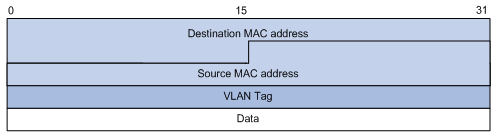
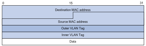
Figure 1-2 describes the structure of the packets with double-layer VLAN tags.
Figure 1-2 Structure of packets with double-layer VLAN tags
Compared with MPLS-based Layer 2 VPN, VLAN-VPN has the following features:
l It provides Layer 2 VPN tunnels that are simpler.
l VLAN-VPN can be implemented through manual configuration. That is, signaling protocol-related configuration is not needed.
The VLAN-VPN feature provides you with the following benefits:
l Saves public network VLAN ID resource.
l You can have VLAN IDs of your own, which is independent of public network VLAN IDs.
l Provides simple Layer 2 VPN solutions for small-sized MANs or intranets.
Implementation of VLAN-VPN
With the VLAN-VPN feature enabled, no matter whether or not a received packet already carries a VLAN tag, the switch will tag the received packet with the default VLAN tag of the receiving port and add the source MAC address to the MAC address table of the default VLAN. When a packet reaches a VLAN-VPN-enabled port:
l If the packet already carries a VLAN tag, the packet becomes a dual-tagged packet.
l Otherwise, the packet becomes a packet carrying the default VLAN tag of the port.
Configuring the TPID for VLAN-VPN Packets
A VLAN tag uses the tag protocol identifier (TPID) field to identify the protocol type of the tag. The value of this field is 0x8100 for IEEE 802.1Q.
Figure 1-3 illustrates the structure of the IEEE 802.1Q VLAN tag in an Ethernet frame.
Figure 1-3 The structure of the VLAN tag in an Ethernet frame
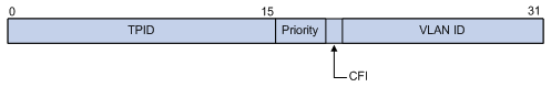
An S3600 switch determines whether a received frame is VLAN tagged by comparing its own TPID with the TPID field in the received frame. If they match, the frame is considered as a VLAN tagged frame. If not, the switch tags the frame with the default VLAN tag of the receiving port.
By default, S3600 series switches adopt the IEEE 802.1Q TPID value 0x8100. Some vendors, however, use other TPID values such as 0x9100. For compatibility with these systems, the S3600 series switches allow you to change the TPID that a port uses when tagging a received VLAN-VPN frame as needed. When doing that, you should set the same TPID on both the customer-side port and the service provider-side port.
The TPID in an Ethernet frame has the same position with the protocol type field in a frame without a VLAN tag. To avoid problems in packet forwarding and handling, you cannot set the TPID value to any of the values in the table below.
Table 1-1 Commonly used protocol type values in Ethernet frames
|
Protocol type |
Value |
|
ARP |
0x0806 |
|
IP |
0x0800 |
|
MPLS |
0x8847/0x8848 |
|
IPX |
0x8137 |
|
IS-IS |
0x8000 |
|
LACP |
0x8809 |
|
802.1x |
0x888E |
Inner-to-Outer Tag Priority Replicating and Mapping
As shown in Figure 1-3, the user priority field is the 802.1p priority of the tag. The value of this 3-bit field is in the range 0 to 7. By configuring inner-to-outer tag priority replicating or mapping for a VLAN-VPN-enabled port, you can replicate the inner tag priority to the outer tag or assign outer tags of different priorities to packets according to their inner tag priorities.
Refer to QoS-QoS Profile part for information about priority.
VLAN-VPN Configuration
VLAN-VPN Configuration Task List
Complete the following tasks to configure VLAN-VPN:
|
Task |
Remarks |
|
Required |
|
|
Optional |
|
|
Configuring the Inner-to-Outer Tag Priority Replicating and Mapping Feature |
Optional |
![]()
As IRF fabric is mutually exclusive with VLAN-VPN, make sure that IRF fabric is disabled on the switch before performing any of the configurations listed in the above table. For information about IRF fabric, refer to IRF Fabric Configuration in this manual.
Enabling the VLAN-VPN Feature for a Port
Follow these steps to enable the VLAN-VPN feature for a port:
|
To do... |
Use the command... |
Remarks |
|
Enter system view |
system-view |
— |
|
Enter Ethernet port view |
interface interface-type interface-number |
— |
|
Enable the VLAN-VPN feature on the port |
vlan-vpn enable |
Required By default, the VLAN-VPN feature is disabled on a port. |
Configuring the TPID Value for VLAN-VPN Packets on a Port
For your device to correctly identify the VLAN tagged frames from the public network, make sure that the TPID you will use is the same as that used on the peer device in the public network.
Follow these steps to configure the TPID for VLAN-VPN packets on a port:
|
To do... |
Use the command... |
Remarks |
|
Enter system view |
system-view |
— |
|
Enter Ethernet port view |
interface interface-type interface-number |
— |
|
Set the TPID value on the port |
vlan-vpn tpid value |
Required Do not set the TPID value to any of the protocol type values listed in Table 1-1. For H3C series switches, the TPID defaults to 0x8100. |
![]()
l Besides the default TPID 0x8100, you can configure only one TPID value on an S3600 switch.
l For the S3600 series to exchange packets with the public network device properly, you should configure the TPID value used by the public network device on both the customer-side port and the service provider-side port.
Configuring the Inner-to-Outer Tag Priority Replicating and Mapping Feature
Make sure that the VLAN-VPN feature is enabled on a port before configuring the inner-to-outer tag priority replicating and mapping feature.
Follow these steps to configure the inner-to-outer tag priority replicating and mapping feature:
|
To do... |
Use the command... |
Remarks |
|
Enter system view |
system-view |
— |
|
Enter Ethernet port view |
interface interface-type interface-number |
— |
|
Enable the inner-to-outer tag priority replicating feature |
vlan-vpn inner-cos-trust enable |
Either of the two configurations is required. By default, neither the inner-to-outer tag priority replicating feature nor the inner-to-outer tag priority mapping feature is enabled. |
|
Enable the inner-to-outer tag priority mapping feature and create a priority mapping |
vlan-vpn priority old-priority remark new-priority |
![]()
l If you have configured the port priority (refer to QoS-QoS Profile Configuration part in this manual), you will be prompted that the port priority configured for the current port gets invalid after you enable the inner-to-outer tag priority replicating feature.
l The inner-to-outer tag priority replicating feature is mutually exclusive with the inner-to-outer tag priority mapping feature.
Displaying and Maintaining VLAN-VPN Configuration
|
To do... |
Use the command... |
Remarks |
|
Display the VLAN-VPN configurations of all the ports |
display port vlan-vpn |
Available in any view |
VLAN-VPN Configuration Example
Transmitting User Packets through a Tunnel in the Public Network by Using VLAN-VPN
Network requirements
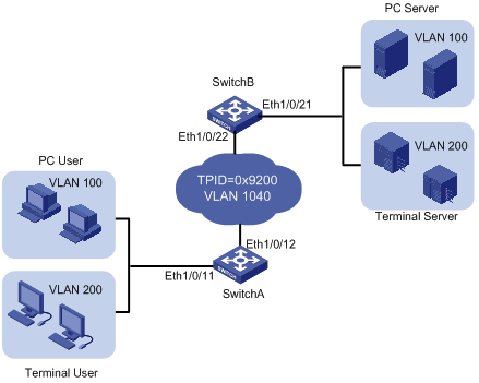
As shown in Figure 1-4, Switch A and Switch B are both S3600 series switches. They connect the users to the servers through the public network.
l PC users and PC servers are in VLAN 100 created in the private network, while terminal users and terminal servers are in VLAN 200, which is also created in the private network. The VLAN VPN connection is established in VLAN 1040 of the public network.
l Switches of other vendors’ are used in the public network. They use the TPID value 0x9200.
l Employ VLAN-VPN on Switch A and Switch B to enable the PC users and PC servers to communicate with each through a VPN, and employ VLAN-VPN on Switch A and Switch B to enable the Terminal users and Terminal servers to communicate with each other through a VPN.
Network diagram
Figure 1-4 Network diagram for VLAN-VPN configuration
Configuration procedure
l Configure Switch A.
# Enable the VLAN-VPN feature on Ethernet 1/0/11 of Switch A and tag the packets received on this port with the tag of VLAN 1040 as the outer VLAN tag.
<SwitchA> system-view
[SwitchA] vlan 1040
[SwitchA-vlan1040] port Ethernet 1/0/11
[SwitchA-vlan1040] quit
[SwitchA] interface Ethernet 1/0/11
[SwitchA-Ethernet1/0/11] vlan-vpn enable
[SwitchA-Ethernet1/0/11] quit
# Set the TPID value of Ethernet 1/0/12 to 0x9200 (for intercommunication with the devices in the public network) and configure the port as a trunk port permitting packets of VLAN 1040.
[SwitchA] interface Ethernet 1/0/12
[SwitchA-Ethernet1/0/12] vlan-vpn tpid 9200
[SwitchA-Ethernet1/0/12] port link-type trunk
[SwitchA-Ethernet1/0/12] port trunk permit vlan 1040
l Configure Switch B.
# Enable the VLAN-VPN feature on Ethernet 1/0/21 of Switch B and tag the packets received on this port with the tag of VLAN 1040 as the outer VLAN tag.
<SwitchB> system-view
[SwitchB] vlan 1040
[SwitchB-vlan1040] port Ethernet 1/0/21
[SwitchB-vlan1040] quit
[SwitchB] interface Ethernet 1/0/21
[SwitchB-Ethernet1/0/21] vlan-vpn enable
# Set the TPID value of Ethernet1/0/22 to 0x9200 (for intercommunication with the devices in the public network) and set the port as a trunk port permitting packets of VLAN 1040.
[SwitchB-Ethernet1/0/22] vlan-vpn tpid 9200
[SwitchB-Ethernet1/0/22] quit
[SwitchB] interface Ethernet 1/0/21
[SwitchB-Ethernet1/0/22] port link-type trunk
[SwitchB-Ethernet1/0/22] port trunk permit vlan 1040
![]()
l Do not configure VLAN 1040 as the default VLAN of Ethernet 1/0/12 of Switch A and Ethernet 1/0/22 of Switch B. Otherwise, the outer VLAN tag of a packet will be removed during transmission.
l In this example, both Ethernet1/0/11 of Switch A and Ethernet1/0/21 of Switch B are access ports. In cases where the ports are trunk ports or hybrid ports, you need to configure the two ports to remove the outer VLAN tags before transmitting packets of VLAN 1040. Refer to VLAN in this manual for detailed configuration.
l Configure the devices in the public network
# As the devices in the public network are from other vendors, only the basic principles are introduced here. That is, you need to configure the devices connecting to Ethernet 1/0/12 of Switch A and Ethernet 1/0/22 of Switch B to permit the corresponding ports to transmit tagged packets of VLAN 1040.
Data transfer process
The following describes how a packet is forwarded from Switch A to Switch B in this example.
1) As Ethernet 1/0/11 of Switch A is a VLAN-VPN port, when a packet from the customer’s network side reaches this port, it is tagged with the default VLAN tag of the port (VLAN 1040).
2) The TPID value of the outer VLAN tag is set to 0x9200 before the packet is forwarded to the public network through Ethernet1/0/12 of Switch A.
3) The outer VLAN tag of the packet remains unchanged while the packet travels in the public network, till it reaches Ethernet1/0/22 of Switch B.
4) After the packet reaches Switch B, it is forwarded through Ethernet1/0/21 of Switch B. As the port belongs to VLAN 1040 and is an access port, the outer VLAN tag (the tag of VLAN 1040) of the packet is removed before the packet is forwarded, which restores the packet to a packet tagged with only the private VLAN tag and enables it to be forwarded to its destination networks.
5) It is the same case when a packet travels from Switch B to Switch A.
2 Selective QinQ Configuration
![]()
The selective QinQ is new to H3C S3600 Series Ethernet Switches.
When configuring selective QinQ, go to these sections for information you are interested in:
l Selective QinQ Configuration
l Selective QinQ Configuration Example
Selective QinQ Overview
Selective QinQ Overview
Selective QinQ is an enhanced application of the VLAN-VPN feature. With the selective QinQ feature, you can configure inner-to-outer VLAN tag mapping, according to which you can add different outer VLAN tags to the packets with different inner VLAN tags.
The selective QinQ feature makes the service provider network structure more flexible. You can classify the terminal users on the port connecting to the access layer device according to their VLAN tags, and add different outer VLAN tags to these users. In the public network, you can configure QoS policies based on outer VLAN tags to assign different priorities to different packets, thus providing differentiated services. See Figure 2-1 for details.
Figure 2-1 Diagram for a selective QinQ implementation
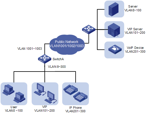
In this implementation, Switch A is an access device of the service provider. The users connecting to it include common customers (in VLAN 8 to VLAN 100), VIPs (in VLAN 101 to VLAN 200), and IP telephone users (in VLAN 201 to VLAN 300). Packets of all these users are forwarded by Switch A to the public network.
After the selective QinQ feature and the inner-to-outer tag mapping feature are enabled on the port connecting Switch A to these users, the port will add different outer VLAN tags to the packets according to their inner VLAN tags. For example, you can configure to add the tag of VLAN 1002 to the packets of IP telephone users in VLAN 201 to VLAN 300 and forward the packets to the VoIP device, which is responsible for processing IP telephone services.
To guarantee the quality of voice packet transmission, you can configure QoS policies in the public network to reserve bandwidth for packets of VLAN 1002 and forward them preferentially.
In this way, you can configure different forwarding policies for data of different type of users, thus improving the flexibility of network management. On the other hand, network resources are well utilized, and users of the same type are also isolated by their inner VLAN tags. This helps to improve network security.
MAC Address Replicating
Like the VLAN-VPN feature, a port with the selective QinQ enabled adds the source MAC addresses of user packets to the MAC address table of the default VLAN on the port. However, the port with selective QinQ enabled can insert an outer VLAN tag other than that of the default VLAN to the packets. Thus, when packets are forwarded from the service provider to users, they may be broadcast if their destination MAC addresses cannot be found in the MAC address table of the outer VLANs.
Figure 2-2 Learn MAC addresses of selective QinQ packets
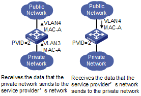
As shown in Figure 2-2, the default VLAN of the port used to receive packets is VLAN 2. The port is configured to receive packets of VLAN 3, tag the received packets with the outer tag of VLAN 4, and add the source MAC addresses (MAC-A) of the packets to the MAC address table of its default VLAN (VLAN 2).
When a response packet is returned to the device from VLAN 4 of the service provider network, the device searches the outbound port for MAC-A in the MAC address table of VLAN 4. However, because the corresponding entry is not added to the MAC address table of VLAN 4, this packet is considered to be a unicast packet with unknown destination MAC address. As a result, this packet will be broadcast to all the ports in VLAN 4, which wastes the network resources and incurs potential security risks.
The S3600 series Ethernet switches provide the inter-VLAN MAC address replicating feature, which can replicate the entries in the MAC address table of the default VLAN to that of the VLAN corresponding to the outer tag. With the inter-VLAN MAC address replicating feature enabled, when a device receives a packet from the service provider network, this device will find the path for the packet by searching the MAC address table of the VLAN corresponding to the outer tag and unicast the packet. Thus, packet broadcast is reduced in selective QinQ applications.
Selective QinQ Configuration
Selective QinQ Configuration Task List
Complete the following tasks to configure selective QinQ:
|
Task |
Remarks |
|
Required |
|
|
Optional |
![]()
If IRF Fabric has been enabled on a device, you cannot enable the VLAN-VPN feature and the selective QinQ feature on any port of the device.
Enabling the Selective QinQ Feature for a Port
The following configurations are required for the selective QinQ feature:
l Enabling the VLAN-VPN feature on the current port
l Configuring the current port to permit packets of specific VLANs (the VLANs whose tags are to be used as the outer VLAN tags are required)
Follow these steps to enable the selective QinQ feature:
|
To do... |
Use the command... |
Remarks |
|
Enter system view |
system-view |
— |
|
Enter Ethernet port view |
interface interface-type interface-number |
— |
|
Configure the outer VLAN tag and enter QinQ view |
vlan-vpn vid vlan-id |
Required |
|
Configure to add outer VLAN tags to the packets with the specific inner VLAN tags |
raw-vlan-id inbound vlan-id-list |
Required By default, the feature of adding an outer VLAN tag to the packets with the specific inner VLAN tags is disabled. |
![]()
Do not enable both the selective QinQ function and the DHCP snooping function on a switch. Otherwise, the DHCP snooping function may operate improperly.
Enabling the Inter-VLAN MAC Address Replicating Feature
Follow these steps to enable the inter-VLAN MAC address replicating feature:
|
To do... |
Use the command... |
Remarks |
|
Enter system view |
system-view |
— |
|
Enable the inter-VLAN MAC address replicating feature |
mac-address-mapping index source-vlan source-vlan-id-list destination-vlan dest-vlan-id |
Required By default, the inter-VLAN MAC address replicating feature is disabled. |
![]()
l On a port, the inter-VLAN MAC address replicating feature can be configured only once for a destination VLAN. If the configuration needs to be modified, you need to remove the existing configuration first.
l With the inter-VLAN MAC address replicating feature disabled, all the MAC address entries that the destination VLAN learns from the other VLANs through this function are removed.
l MAC address entries obtained through the inter-VLAN MAC address replicating feature cannot be removed manually. To remove a MAC address entry of this kind, you need to disable the inter-VLAN MAC address replicating feature first.
l VLAN 4093 is a special VLAN reserved for the IRF fabric feature. It can not serve as the destination VLAN of the inter-VLAN MAC address replicating feature to receive MAC address entries from the other VLANs.
Selective QinQ Configuration Example
Processing Private Network Packets by Their Types
Network requirements
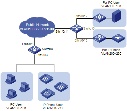
l Ethernet 1/0/3 of Switch A provides public network access for PC users and IP phone users. PC users belong to VLAN 100 through VLAN 108, and IP phone users belong to VLAN 200 through VLAN 230. Ethernet 1/0/5 of Switch A is connected to the public network. The peer end of Switch A is Switch B.
l Ethernet 1/0/11 of Switch B is connected to the public network. Ethernet 1/0/12 and Ethernet1/0/13 of Switch B provide network access for PC servers belonging to VLAN 100 through VLAN 108 and voice gateways (for IP phone users) belonging to VLAN 200 through VLAN 230 respectively.
l The public network permits packets of VLAN 1000 and VLAN 1200. Apply QoS policies for these packets to reserve bandwidth for packets of VLAN 1200. That is, packets of VLAN 1200 have higher transmission priority over packets of VLAN 1000.
l Employ the selective QinQ feature on Switch A and Switch B to differentiate traffic of PC users from that of IP phone users, for the purpose of using QoS policies to guarantee higher priority for voice traffic.
l To reduce broadcast packets in the network, enable the inter-VLAN MAC address replicating feature for selective QinQ.
Network diagram
Figure 2-3 Network diagram for selective QinQ configuration
Configuration procedure
l Configure Switch A.
# Create VLAN 1000, VLAN 1200 and VLAN 5 (the default VLAN of Ethernet 1/0/3) on SwitchA.
<SwitchA> system-view
[SwitchA] vlan 1000
[SwitchA-vlan1000] quit
[SwitchA] vlan 1200
[SwitchA-vlan1200] quit
[SwitchA] vlan 5
[SwitchA-vlan5] quit
# Configure Ethernet 1/0/5 as a hybrid port and configure it not to remove VLAN tags when forwarding packets of VLAN 5, VLAN 1000, and VLAN 1200.
[SwitchA] interface Ethernet 1/0/5
[SwitchA-Ethernet1/0/5] port link-type hybrid
[SwitchA-Ethernet1/0/5] port hybrid vlan 5 1000 1200 tagged
[SwitchA-Ethernet1/0/5] quit
# Configure Ethernet 1/0/3 as a hybrid port and configure VLAN 5 as its default VLAN. Configure Ethernet 1/0/3 to remove VLAN tags when forwarding packets of VLAN 5, VLAN 1000, and VLAN 1200.
[SwitchA] interface Ethernet 1/0/3
[SwitchA-Ethernet1/0/3] port link-type hybrid
[SwitchA-Ethernet1/0/3] port hybrid pvid vlan 5
[SwitchA-Ethernet1/0/3] port hybrid vlan 5 1000 1200 untagged
# Enable the VLAN-VPN feature on Ethernet 1/0/3.
[SwitchA-Ethernet1/0/3] vlan-vpn enable
# Enable the selective QinQ feature on Ethernet 1/0/3 to tag packets of VLAN 100 through VLAN 108 with the tag of VLAN 1000 as the outer VLAN tag, and tag packets of VLAN 200 through VLAN 230 with the tag of VLAN 1200 as the outer VLAN tag.
[SwitchA-Ethernet1/0/3] vlan-vpn vid 1000
[SwitchA-Ethernet1/0/3-vid-1000] raw-vlan-id inbound 100 to 108
[SwitchA-Ethernet1/0/3-vid-1000] quit
[SwitchA-Ethernet1/0/3] vlan-vpn vid 1200
[SwitchA-Ethernet1/0/3-vid-1200] raw-vlan-id inbound 200 to 230
# Enable the inter-VLAN MAC address replicating feature to replicate the MAC address entries of the MAC address tables of the outer VLANs to the MAC address table of the default VLAN, and replicate the MAC address entries of the MAC address table of the default VLAN to the MAC address tables of the outer VLANs.
[SwitchA-Ethernet1/0/3-vid-1200] quit
[SwitchA-Ethernet1/0/3] mac-address mapping 0 source-vlan 5 destination-vlan 1000
[SwitchA-Ethernet1/0/3] mac-address mapping 1 source-vlan 5 destination-vlan 1200
[SwitchA-Ethernet1/0/3] quit
[SwitchA] interface Ethernet 1/0/5
[SwitchA-Ethernet1/0/5] mac-address mapping 0 source-vlan 1000 1200 destination-vlan 5
After the above configuration, packets of VLAN 100 through VLAN 108 (that is, packets of PC users) are tagged with the tag of VLAN 1000 as the outer VLAN tag when they are forwarded to the public network by Switch A; and packets of VLAN 200 through VLAN 230 (that is, packets of IP phone users) are tagged with the tag of VLAN 1200 as the outer VLAN tag when they are forwarded to the public network.
l Configure Switch B.
# Create VLAN 1000, VLAN 1200, VLAN 12 (the default VLAN of Ethernet1/0/12) and VLAN 13 (the default VLAN of Ethernet1/0/13) on Switch B.
<SwitchB> system-view
[SwitchB] vlan 1000
[SwitchB-vlan1000] quit
[SwitchB] vlan 1200
[SwitchB-vlan1200] quit
[SwitchB] vlan 12 to 13
# Configure Ethernet 1/0/11 as a hybrid port, and configure Ethernet 1/0/11 not to remove VLAN tags when forwarding packets of VLAN 12, VLAN 13, VLAN 1000, and VLAN 1200.
<SwitchB> system-view
[SwitchB] interface Ethernet 1/0/11
[SwitchB-Ethernet1/0/11] port link-type hybrid
[SwitchB-Ethernet1/0/11] port hybrid vlan 12 13 1000 1200 tagged
# Configure Ethernet1/0/12 as a hybrid port and configure VLAN 12 as its default VLAN . Configure Ethernet 1/0/12 to remove VLAN tags when forwarding packets of VLAN 12 and VLAN 1000.
[SwitchB] interface Ethernet 1/0/12
[SwitchB-Ethernet1/0/12] port link-type hybrid
[SwitchB-Ethernet1/0/12] port hybrid pvid vlan 12
[SwitchB-Ethernet1/0/12] port hybrid vlan 12 1000 untagged
[SwitchB-Ethernet1/0/12] quit
# Configure Ethernet 1/0/13 as a hybrid port and configure VLAN 13 as its default VLAN . Configure Ethernet 1/0/13 to remove VLAN tags when forwarding packets of VLAN 13 and VLAN 1200.
[SwitchB] interface Ethernet 1/0/13
[SwitchB-Ethernet1/0/13] port link-type hybrid
[SwitchB-Ethernet1/0/13] port hybrid pvid vlan 13
[SwitchB-Ethernet1/0/13] port hybrid vlan 13 1200 untagged
After the above configuration, Switch B can forward packets of VLAN 1000 and VLAN 1200 to the corresponding servers through Ethernet 1/0/12 and Ethernet 1/0/13 respectively.
To make the packets from the servers be transmitted to the clients in the same way, you need to configure the selective QinQ feature and the inter-VLAN MAC address replicating feature on Ethernet 1/0/12 and Ethernet 1/0/13. The configuration on Switch B is similar to that on Switch A and is thus omitted.
![]()
l The port configuration on Switch B is only an example for a specific network requirement. The key to this example is to enable the ports to receive and forward packets of specific VLANs. So you can also configure the ports as trunk ports. Refer to VLAN Configuration for details.
l A selective QinQ-enabled device tags a user packet with an outer VLAN tag regardless of the VLAN tag of the user packet, so there is no need to configure user VLANs on the device.
l Make sure the packets of the default VLAN of a selective QinQ-enabled port are permitted on both the local port and the port connecting to the public network.
![]()
Two features, the BPDU Tunnel support for packets of multiple protocols and adjusting tunnel packet MAC addresses, are newly added. For details, refer to BPDU Tunnel Configuration.
When configuring BPDU tunnel, go to these sections for information you are interested in:
l Displaying and Maintaining BPDU Tunnel Configuration
l BPDU Tunnel Configuration Example
BPDU Tunnel Overview
Introduction to the BPDU Tunnel Feature
Normally, Layer 2 protocols are needed in a LAN for network topology maintenance and management. For example, spanning tree protocol (STP) is used for maintaining spanning trees and preventing loops. Huawei group management protocol (HGMP) is used for managing network topology and devices in a network.
When multiple branch networks of an organization are connected together through a public network, you can combine the corresponding network nodes into one so as to maintain the branch networks as a whole. This requires the packets of some of the user’s Layer 2 protocol packets be transmitted across the provider’s network without getting involved in the computation of the public network.
The BPDU Tunnel feature is designed to address the above requirements. It enables some Layer 2 protocol packets of private networks to be transmitted along tunnels established in the public network.
BPDU Tunnel Fundamental
Layer 2 protocol packet identification
Different from the processing of data packets, a Layer 2 protocol packet is classified first when it reaches a network device. A Layer 2 protocol packet conforming to IEEE standards carries a special destination MAC address (for example, the destination MAC address of an STP protocol packet is 0180-c200-0000) and contains a type field. Some proprietary protocols adopt the same packet structure, where a private MAC address is used to identify the corresponding proprietary protocol, and the type field is used to identify the specific protocol type.
Transmitting BPDU packets transparently
As shown in Figure 3-1, the network on the top is the service provider network, and the one on the bottom is a customer network. The service provider network contains edge devices connecting the customer network to the service provider network. The customer network contains Network A and Network B. You can make the BPDU packets of the customer network to be transmitted in the service provider network transparently by enabling the BPDU tunnel feature on the edge devices at both ends of the service provider network.
Figure 3-1 BPDU Tunnel network hierarchy
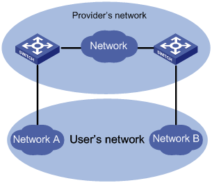
l When a BPDU packet coming from a customer network reaches an edge device in the service provider network, the edge device changes the destination MAC address carried in the packet from a protocol-specific MAC address to a private multicast MAC address, which can be defined using a command. A packet with this multicast address as its destination address is called a tunnel packet. In the service provider network, the tunnel packet can be forwarded as a normal data packet.
l Before the device in the service provider network forwards the packet to the destination customer network, the edge device will identify the tunnel packet, determine the packet type based on the type field in the packet, restore its destination MAC address to the original protocol-specific MAC address and then forward the packet to the access device on the user side. This ensures the packet to be forwarded is consistent with the packet before entering the tunnel. So, a tunnel here acts as a local link for user devices. It enables Layer 2 protocols to run on a virtual local network.
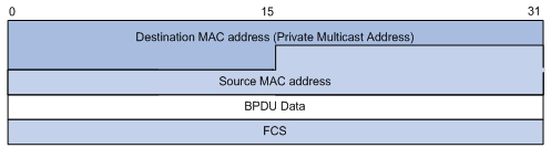
Figure 3-2 and Figure 3-3 show the structure of a BPDU packet before and after it enter a BPDU tunnel.
Figure 3-2 The structure of a BPDU packet before it enters a BPDU tunnel
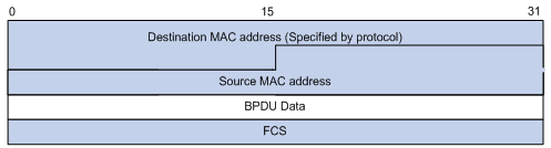
Figure 3-3 The structure of a BPDU packet after it enters a BPDU tunnel
![]()
To prevent the devices in the service provider network from processing the tunnel packets as other protocol packets, the MAC address of a tunnel packet must be a multicast address uniquely assigned to the BPDU tunnel in the service provider network.
BPDU Tunnel Configuration
You can establish BPDU tunnels between S3600 series Ethernet switches for the packets of the following protocols:
l LACP (link aggregation control protocol)
l STP (spanning tree protocol)
l HGMP-related protocols, including: NDP (neighbor discovery protocol), NTDP (neighbor topology discovery protocol), cluster MRC (cluster member remote control), and HABP (Huawei authentication bypass protocol)
l Proprietary protocols of other vendors, including CDP (CISCO discovery protocol), PAGP (port aggregation protocol), PVST (per-VLAN spanning tree), VTP (VLAN trunk protocol), and UDLD (uni-directional link discovery)
Configuration Prerequisites
The edge devices can communicate with the user devices properly.
Configuring a BPDU Tunnel
Follow these steps to configure a BPDU tunnel:
|
To do... |
Use the command... |
Remarks |
|
Enter system view |
system-view |
— |
|
Configure a private multicast MAC address for packets transmitted along the tunnel |
bpdu-tunnel tunnel-dmac mac-address |
Optional By default, the destination MAC address for packets transmitted along a BPDU tunnel is 010f-e200-0003. |
|
Enter Ethernet port view |
interface interface-type interface-number |
— |
|
Enable BPDU tunnel for packets of a specific protocol |
bpdu-tunnel protocol-type |
Required By default, BPDU tunnel is disabled for packets of any protocol. |
![]()
l The BPDU Tunnel is unavailable to all the ports of a device if the device has the fabric feature enabled on one of its ports.
l If BPDU tunnel transparent transmission is enabled for packets of a protocol, the protocol cannot be enabled on the port. For example, if you execute the bpdu-tunnel lacp command, the lacp enable command cannot be executed on the port.
l The bpdu-tunnel stp command is mutually exclusive with the vlan-vpn tunnel command. Refer to MSTP part of this manual for details.
l To enable BPDU tunnel transmission for PAGP packets, LACP packets and UDLD packets, make sure that the links the service provider provides are point-to-point links. Otherwise, these protocols cannot operate properly.
l Because the NDP configuration and NTDP configuration cannot be synchronized to ports in an aggregation group, make sure that NDP and NTDP are not enabled on any port in an aggregation group before enabling the service provider network to use aggregation group to transmit HGMP packets through BPDU tunnels.
l The bpdu-tunnel cdp command is mutually exclusive with the voice vlan legacy command. Refer to Voice VLAN part of this manual for details.
l If a BPDU-tunnel-enabled port receives a tunnel packet from the customer’s network, errors occur in the network and the tunnel packet will be dropped directly.
Displaying and Maintaining BPDU Tunnel Configuration
|
To do... |
Use the command... |
Remarks |
|
Display the private multicast MAC address used by the tunnel packets |
display bpdu-tunnel |
Available in any view |
BPDU Tunnel Configuration Example
Transmitting STP Packets Through a Tunnel
Network requirements
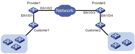
l Customer1 and Customer2 are devices operating in a customer network; Provider1 and Provider2 are edge devices operating in the service provider network. The two devices receive data from the customer network by using Ethernet1/0/1 and Ethernet1/0/2 respectively.
l Provider1 and Provider2 are connected through trunk links, which permit packets of all VLANs.
l Enable the service provider network to transmit STP packets of the customer network through BPDU tunnel. The destination MAC address for tunnel packets is 010f-e233-8b22.
l Enable the VLAN-VPN feature for the service provider network, and enable the service provider network to use VLAN 100 to transmit data packets of the customer network.
Network diagram
Figure 3-4 Network diagram for BPDU Tunnel configuration
Configuration procedure
1) Configure Provide1.
# Disable STP on Ethernet1/0/1.
<Sysname> system-view
[Sysname] interface Ethernet 1/0/1
[Sysname-Ethernet1/0/1] stp disable
# Enable the BPDU tunnel feature for STP BPDUs on Ethernet1/0/1.
[Sysname-Ethernet1/0/1] bpdu-tunnel stp
# Enable the VLAN-VPN feature on Ethernet1/0/1 and use VLAN 100 to transmit user data packets through BPDU tunnels.
[Sysname-Ethernet1/0/1] port access vlan 100
[Sysname-Ethernet1/0/1] vlan-vpn enable
# Configure the destination MAC address for protocol packets transmitted through the BPDU tunnel.
[Sysname-Ethernet1/0/1] quit
[Sysname] bpdu-tunnel tunnel-dmac 010f-e233-8b22
# Configure Ethernet1/0/2 as a trunk port that permits packets of all VLANs.
[Sysname] interface Ethernet 1/0/2
[Sysname-Ethernet1/0/2] port link-type trunk
[Sysname-Ethernet1/0/2] port trunk permit vlan all
2) Configure Provider2.
# Disable STP on Ethernet1/0/4.
<Sysname> system-view
[Sysname] interface Ethernet 1/0/4
[Sysname-Ethernet1/0/4] stp disable
# Enable BPDU tunnel for STP packets.
[Sysname-Ethernet1/0/4] bpdu-tunnel stp
# Enable VLAN-VPN and use VLAN 100 to transmit user data packets through BPDU tunnels.
[Sysname-Ethernet1/0/4] port access vlan 100
[Sysname-Ethernet1/0/4] vlan-vpn enable
# Configure the destination MAC address for the packets transmitted in the tunnel.
[Sysname-Ethernet1/0/4] quit
[Sysname] bpdu-tunnel tunnel-dmac 010f-e233-8b22
# Configure Ethernet1/0/3 as a trunk port that permits packets of all VLANs.
[Sysname] interface Ethernet 1/0/3
[Sysname-Ethernet1/0/3] port link-type trunk
[Sysname-Ethernet1/0/3] port trunk permit vlan all