- Table of Contents
-
- H3C S3600 Operation Manual-Release 1602(V1.02)
- 00-1Cover
- 00-2Product Overview
- 01-CLI Operation
- 02-Login Operation
- 03-Configuration File Management Operation
- 04-VLAN Operation
- 05-IP Address and Performance Operation
- 06-Voice VLAN Operation
- 07-GVRP Operation
- 08-Port Basic Configuration Operation
- 09-Link Aggregation Operation
- 10-Port Isolation Operation
- 11-Port Security-Port Binding Operation
- 12-DLDP Operation
- 13-MAC Address Table Management Operation
- 14-Auto Detect Operation
- 15-MSTP Operation
- 16-Routing Protocol Operation
- 17-Multicast Operation
- 18-802.1x and System Guard Operation
- 19-AAA Operation
- 20-Web Authentication Operation
- 21-MAC Address Authentication Operation
- 22-VRRP Operation
- 23-ARP Operation
- 24-DHCP Operation
- 25-ACL Operation
- 26-QoS-QoS Profile Operation
- 27-Web Cache Redirection Operation
- 28-Mirroring Operation
- 29-IRF Fabric Operation
- 30-Cluster Operation
- 31-PoE-PoE Profile Operation
- 32-UDP Helper Operation
- 33-SNMP-RMON Operation
- 34-NTP Operation
- 35-SSH Operation
- 36-File System Management Operation
- 37-FTP-SFTP-TFTP Operation
- 38-Information Center Operation
- 39-System Maintenance and Debugging Operation
- 40-VLAN-VPN Operation
- 41-HWPing Operation
- 42-IPv6 Management Operation
- 43-DNS Operation
- 44-Smart Link-Monitor Link Operation
- 45-Access Management Operation
- 46-Appendix
- Related Documents
-
| Title | Size | Download |
|---|---|---|
| 44-Smart Link-Monitor Link Operation | 193.76 KB |
Table of Contents
Operating Mechanism of Smart Link
Configuring a Smart Link Device
Configuring Associated Devices
Displaying and Maintaining Smart Link
Smart Link Configuration Example
Implementing Link Redundancy Backup
Displaying Monitor Link Configuration
Monitor Link Configuration Example
Implementing Collaboration Between Smart Link and Monitor Link
When configuring smart link, go to these sections for information you are interested in:
l Displaying and Maintaining Smart Link
l Smart Link Configuration Example
Smart Link Overview
As shown in Figure 1-1, dual-uplink networking is widely applied currently. Usually, Spanning Tree Protocol (STP) is used to implement link redundancy backup in the network. However, STP is not suitable for users with a high demand for convergence time. Smart Link can achieve active/standby link redundancy backup and fast convergence to meet the user demand.
Smart Link has the following features:
l Active/standby backup for dual-uplink networking
l Simple configuration and operation
Basic Concepts in Smart Link
Smart link group
A smart link group consists of two member ports, one master port and one slave port. Normally, only one port (master or slave) is active, and the other port is blocked, that is, in the standby state. When link failure occurs on the port in active state, the smart link group will block the port automatically and turn standby state to active state on the blocked port.
Figure 1-1 Network diagram of Smart Link
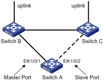
In Figure 1-1, Ethernet 1/0/1 and Ethernet 1/0/2 on Switch A are two member ports of a smart link group.
Master port
The master port can be either an Ethernet port or a manually-configured or static LACP aggregation group. For example, you can configure Ethernet 1/0/1 of switch A in Figure 1-1 as the master port through the command line.
Slave port
The slave port can be either an Ethernet port or a manually-configured or static LACP aggregation group. For example, you can configure Ethernet 1/0/2 of switch A in Figure 1-1 as the slave port through the command line.
Flush message
When a forwarding link fails, the device will switch the traffic to the blocked standby link. The former forwarding entries of each device in the network are no longer suitable for the new topology, so MAC address forwarding entries and ARP entries must be updated throughout the network. In this case, the smart link group sends flush messages to notify other devices to refresh MAC address forwarding entries and ARP entries.
Control VLAN for sending flush messages
This control VLAN sends flush messages. When link switching occurs, the device (Switch A in Figure 1-1) broadcasts flush messages in this control VLAN.
Control VLAN for receiving flush messages
This control VLAN is used for receiving and processing flush messages. When link switching occurs, the devices (Switch B and Switch C in Figure 1-1) receive and process flush messages of this control VLAN, and then refresh MAC forwarding table entries and ARP entries.
![]()
l Currently, the member ports of a smart link group cannot be dynamic link aggregation groups.
l If the master port or slave port of a smart link group is a link aggregation group, you cannot remove this link aggregation group directly or change the aggregation group into a dynamic aggregation group. Before removing this aggregation group, you must unbind the link aggregation group from the Smart Link.
Operating Mechanism of Smart Link
Figure 1-2 Network diagram of Smart Link operating mechanism
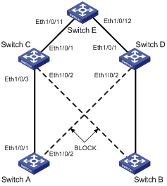
As shown in Figure 1-2, Ethernet 1/0/1 on Switch A is active and Ethernet 1/0/2 on Switch A is blocked. When the link connected to Ethernet 1/0/1 fails, Ethernet 1/0/1 is blocked automatically, and the state of Ethernet 1/0/2 turns to active state.
l When link switching occurs in the smart link group, MAC forwarding entries and ARP entries of each device in the network may be out of date. In order to guarantee correct packet transmission, you must enable the Smart Link device to send flush messages to notify the other devices in the network to refresh their own MAC forwarding entries and ARP entries. In this case, all the uplink devices must be capable of identifying flush messages from the smart link group and refreshing MAC forwarding entries and ARP entries.
l On a Smart Link–enabled device, if a port is blocked due to link failure, the port remains blocked after the link recovers from the failure, and does not preempt the traffic resource. Therefore, the traffic stays stable. The port does not come into the forwarding state until the next link switching.
Configuring Smart Link
![]()
Before configuring a member port of a smart link group, you must:
l Disable the port to avoid loops, thus preventing broadcast storm.
l Disable STP on the port.
After completing the configuration, you need to enable the Ethernet ports disabled before configuring the smart link group.
Configuration Task List
Complete the following tasks to configure Smart Link:
|
Task |
Remarks |
|
|
Create a smart link group |
Required |
|
|
Add member ports to the smart link group |
||
|
Enable the function of sending flush messages in the specified control VLAN |
||
|
Enable the function of processing flush messages received from the specified control VLAN |
Required |
|
Configuring a Smart Link Device
A Smart Link device refers to a device on which Smart Link is enabled and a smart link group is configured, and that sends flush messages from the specified control VLAN. A member port of a smart link group can be either an Ethernet port or a manually-configured or static LACP aggregation group. You can configure a port or a link aggregation group as a member of a smart link group.
Follow these steps to configure Smart Link (with ports as the members of the smart link group):
|
To do… |
Use the command… |
Remarks |
|
|
Enter system view |
system-view |
— |
|
|
Create a smart link group and enter smart link group view |
smart-link group group-id |
Required |
|
|
Enable the function of sending flush messages in the specified control VLAN |
flush enable control-vlan vlan-id |
Required By default, no control VLAN for sending flush messages is specified. |
|
|
Configure a port as a smart link group member |
smart link group view |
port interface-type interface-number { master | slave } |
Required Use either approach |
|
Ethernet port view |
quit |
||
|
interface interface-type interface-number |
|||
|
port smart-link group group-id { master | slave } |
|||
Follow these steps to configure Smart Link (with link aggregation groups are the members of the smart link group):
|
To do… |
Use the command… |
Remarks |
|
Enter system view |
system-view |
— |
|
Create a smart link group and enter smart link group view |
smart-link group group-id |
Required |
|
Configure a link aggregation group as a member of the smart link group |
link-aggregation group group-id { master | slave } |
Optional |
|
Enable the function of sending flush messages in the specified control VLAN |
flush enable control-vlan vlan-id |
Optional By default, no control VLAN for sending flush messages is specified. |
Configuring Associated Devices
An associated device mentioned in this document refers to a device that supports Smart Link and locally configured to process flush messages received from the specified control VLAN so as to work with the corresponding Smart Link device. As shown in Figure 1-2, all the devices including Switch C, Switch D, and Switch E on the active and backup links connecting the Smart Link device (Switch A) and the target uplink device (Switch E) are all associated devices.
However, you do not have to enable all the ports of an associated device to process flush messages received from the specified control VLAN. You need to enable this function only on the ports that are on the active and backup links connecting the Smart Link device and the target device. As shown in Figure 1-2, you need to enable this function on Ethernet 1/0/2 and Ethernet 1/0/3 of Switch C, Ethernet 1/0/2 and Ethernet 1/0/3 of Switch D, and Ethernet 1/0/11 and Ethernet 1/0/12 of Switch E.
Follow these steps to enable the specified port to process flush messages received from the specified control VLAN:
|
To do… |
Use the command… |
Remarks |
|
|
Enter system view |
system-view |
— |
|
|
Enable the specified port(s) to process flush messages received from the control VLAN |
System view |
smart-link flush enable control-vlan vlan-id port interface-type interface-number [ to interface-type interface-number ] |
Required, use either approach. By default, no control VLAN for receiving flush messages is specified. |
|
Ethernet port view |
interface interface-type interface-number |
||
|
smart-link flush enable control-vlan vlan-id |
|||
Precautions
When configuring Smart Link, pay attention to the following points:
1) A port or a link aggregation group cannot serve as a member port for two smart link groups. On the other hand, a port or a link aggregation group cannot serve as a member for a smart link group and a monitor link group at the same time.
2) STP cannot be enabled on the member ports of a smart link group. An STP-enabled port or a link aggregation group with an STP-enabled port cannot serve as a member port for a smart link group.
3) A smart link/monitor link group with members cannot be deleted.
4) Smart Link/Monitor Link is mutually exclusive with remote port mirroring.
5) If you configure both the Smart Link and Monitor Link functions on an Intelligent Resilient Fabric (IRF) enabled device, the Smart Link and Monitor Link functions will function abnormally. Thus, you are recommended to disable the IRF function when configuring the Smart Link or Monitor Link function.
6) When a Combo port operates as a member port of a smart link group, the optical port and the electrical port of the Combo port must not be both engaged with a cable at the same time.
7) When you copy a port, the smart link/monitor link group member information configured on the port will not be copied to other ports.
8) If a single port is specified as a member of a smart link/monitor link group, you cannot execute the lacp enable command on this port or add this port into other dynamic link aggregation groups, because these operations will make this port become a link aggregation group member.
9) If no control VLAN is configured for flush message processing, the device will forward received flush messages without processing them.
10) If the control VLAN for receiving flush messages configured on an associated device is different than the one for sending flush messages configured on the corresponding Smart Link device, the device will forward received flush messages without processing them.
11) In the static or manual link aggregation group which serves as a smart link group member, if a member port can process flush messages, this function cannot be synchronized to the other ports in the aggregation group automatically, that is, the other member ports in the aggregation group cannot process flush messages. The function of processing flush messages must be manually configured for each port in the aggregation group.
12) The VLAN configured as a control VLAN to send and receive flush messages must exist. You cannot directly remove the control VLAN. When a dynamic VLAN is configured as the control VLAN for the smart link group, this VLAN will become a static VLAN, and the prompt information is displayed.
Displaying and Maintaining Smart Link
|
To do… |
Use the command… |
Remarks |
|
Display the information of a smart link group |
display smart-link group { group-id | all } |
Available in any view. |
|
Display the statistics information of flush messages received and processed by the current device |
display smart-link flush |
|
|
Clear flush message statistics |
reset smart-link packets counter |
Available in user view. |
Smart Link Configuration Example
Implementing Link Redundancy Backup
Network requirements
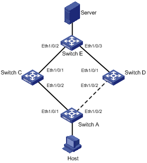
As shown in Figure 1-3, Switch A is an H3C S3600 series Ethernet switch. Switch C, Switch D and Switch E support Smart Link. Configure Smart Link feature to provide remote PCs with reliable access to the server.
Network diagram
Figure 1-3 Network diagram for Smart Link configuration
Configuration procedure
1) Configure a smart link group on Switch A and configure member ports for it. Enable the function of sending flush messages in Control VLAN 1.
# Enter system view.
<switchA> system-view
# Enter Ethernet port view. Disable STP on Ethernet 1/0/1 and Ethernet 1/0/2.
[SwitchA] interface Ethernet 1/0/1
[SwitchA-Ethernet1/0/1] stp disable
[SwitchA-Ethernet1/0/1] quit
[SwitchA] interface Ethernet 1/0/2
[SwitchA-Ethernet1/0/2] stp disable
# Return to system view.
[SwitchA-Ethernet1/0/2] quit
# Create smart link group 1 and enter the corresponding smart link group view.
[SwitchA] smart-link group 1
# Configure Ethernet 1/0/1 as the master port and Ethernet 1/0/2 as the slave port for smart link group 1.
[SwitchA-smlk-group1] port Ethernet 1/0/1 master
[SwitchA-smlk-group1] port Ethernet 1/0/2 slave
# Configure to send flush messages within VLAN 1.
[SwitchA-smlk-group1] flush enable control-vlan 1
2) Enable the function of processing flush messages received from VLAN 1 on Switch C.
# Enter system view.
<SwitchC> system-view
# Enable the function of processing flush messages received from VLAN 1 on Ethernet 1/0/2.
<SwitchC> smart-link flush enable control-vlan 1 port Ethernet 1/0/2
3) Enable the function of processing flush messages received from VLAN 1 on Switch D.
# Enter system view.
<SwitchD> system-view
# Enable the function of processing flush messages received from VLAN 1 on Ethernet 1/0/2.
[SwitchD] smart-link flush enable control-vlan 1 port Ethernet 1/0/2
4) Enable the function of processing flush messages received from VLAN 1 on Switch E.
# Enter system view.
<SwitchE> system-view
# Enable the function of processing flush messages received from VLAN 1 on Ethernet 1/0/2 and Ethernet 1/0/3.
[SwitchE] smart-link flush enable control-vlan 1 port Ethernet 1/0/2 to Ethernet 1/0/3
When configuring Monitor Link, go to these sections for information you are interested in:
l Introduction to Monitor Link
l Displaying Monitor Link Configuration
l Monitor Link Configuration Example
Introduction to Monitor Link
Monitor Link is a collaboration scheme introduced to complement for Smart Link. It is used to monitor uplink and to perfect the backup function of Smart Link.
A monitor Link consists of an uplink port and one or multiple downlink ports. When the link for the uplink port of a monitor link group fails, all the downlink ports in the monitor link group are forced down. When the link for the uplink port recovers, all the downlink ports in the group are re-enabled.
Figure 2-1 Network diagram for a monitor link group implementation
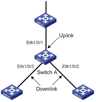
As shown in Figure 2-1, the monitor link group configured on the device Switch A consists of an uplink port (Ethernet 1/0/1) and two downlink ports (Ethernet 1/0/2 and Ethernet 1/0/3). A member port can be an Ethernet port, static LACP aggregation group, manual link aggregation group, or smart link group. A smart link group can serve as the uplink port only.
How Monitor Link Works
Figure 2-2 Network diagram for a monitor link group implementation
As shown in Figure 2-2, the devices Switch C and Switch D are connected to the uplink device Switch E. Switch C is configured with a monitor link group, where Ethernet 1/0/1 is the uplink port, while Ethernet 1/0/2 and Ethernet 1/0/3 are the downlink ports. Switch A is configured with a smart link group, where Ethernet 1/0/1 is the master port and Ethernet 1/0/2 is the slave port.
l If Switch C is not configured with monitor link group, when the link for the uplink port Ethernet 1/0/1 on Switch C fails, the links in the smart link group are not switched because the link for the master port Ethernet 1/0/1 of Switch A configured with smart link group operates normally. Actually, however, the traffic on Switch A cannot be up-linked to Switch E through the link of Ethernet 1/0/1.
![]()
l Currently, member ports of a monitor link group cannot be dynamic link aggregation groups.
l If the uplink or downlink port in the monitor link group is a link aggregation group, you cannot directly delete this aggregation group or change this aggregation group into a dynamic aggregation group. To delete this aggregation group, you must first unbind this aggregation group from the Monitor Link.
Configuring Monitor Link
![]()
Before configuring a monitor link group, you must create a monitor link group and configure member ports for it. A monitor link group consists of an uplink port and one or multiple downlink ports. The uplink port can be a manually-configured or static LACP link aggregation group, an Ethernet port, or a smart link group. The downlink ports can be manually-configured link aggregation groups or static LACP link aggregation groups, or Ethernet ports.
Configuration Task List
Complete the following tasks to configure Monitor Link:
|
Task |
Remarks |
|
Required |
|
|
Required |
|
|
Required |
Creating a Monitor Link Group
Follow these steps to create a monitor link group:
|
To do… |
Use the command… |
Remarks |
|
Enter system view |
system-view |
— |
|
Create a monitor link group |
monitor-link group group-id |
Required |
Configuring the Uplink Port
Follow these steps to configure the uplink port:
|
To do… |
Use the command… |
Remarks |
||
|
Enter system view |
system-view |
— |
||
|
Enter the specified monitor link group view |
monitor-link group group-id |
— |
||
|
Configure the uplink port for the monitor link group |
Configure the specified link aggregation group as the uplink port of the monitor link group |
link-aggregation group group-id uplink |
Required Use any of the three approaches |
|
|
Configure the specified smart link group as the uplink port of the monitor link group |
smart-link group group-id uplink |
|||
|
Configure the specified Ethernet port as the uplink port of the monitor link group |
Monitor link group view |
port interface-type interface-number uplink |
||
|
Ethernet port view |
quit |
|||
|
interface interface-type interface-number |
||||
|
port monitor-link group group-id uplink |
||||
Configuring a Downlink Port
Follow these steps to configure a downlink port:
|
To do… |
Use the command… |
Remarks |
||
|
Enter system view |
system-view |
— |
||
|
Enter the specified monitor link group view |
monitor-link group group-id |
Required |
||
|
Configure a downlink port for the monitor link group |
Configure the specified link aggregation group as a downlink port of the monitor link group |
link-aggregation group group-id downlink |
Required Use either approach |
|
|
Configure the specified Ethernet port as a downlink port of the monitor link group |
Monitor link group view |
port interface-type interface-number downlink |
||
|
Ethernet port view |
quit |
|||
|
interface interface-type interface-number |
||||
|
port monitor-link group group-id downlink |
||||
![]()
l A smart link/monitor link group with members cannot be deleted. A smart link group as a monitor link group member cannot be deleted.
l The smart link/monitor link function and the port mirroring function are incompatible with each other.
l If a single port is specified as a smart link/monitor link group member, do not use the lacp enable command on the port or add the port to another dynamic link aggregation group because doing so will cause the port to become an aggregation group member.
l Using the copy command on a port does not copy the smart link/monitor link group member information configured on the port to any other port.
Displaying Monitor Link Configuration
|
To do… |
Use the command… |
Remarks |
|
Display the information about one or all monitor link groups |
display monitor-link group { group-id | all } |
Available in any view. |
Monitor Link Configuration Example
Implementing Collaboration Between Smart Link and Monitor Link
Network requirements
As shown in Figure 2-3, the PCs access the server and Internet through the switch. Configure Smart Link and Monitor Link to prevent the PCs from failing to access the server and Internet due to uplink link or port failure.
Network diagram
Figure 2-3 Network diagram for Monitor Link configuration
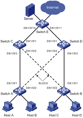
Configuration procedure
1) Enable Smart Link on Switch A and Switch B to implement link redundancy backup. Perform the following configuration on Switch A. The configuration on Switch B is the same as on Switch A.
# Enter system view.
<switchA> system-view
# Enter Ethernet port view. Disable STP on Ethernet1/0/1 and Ethernet1/0/2.
[SwitchA] interface Ethernet 1/0/1
[SwitchA-Ethernet1/0/1] stp disable
[SwitchA-Ethernet1/0/1] quit
[SwitchA] interface Ethernet 1/0/2
[SwitchA-Ethernet1/0/2] stp disable
# Return to system view.
[SwitchA-Ethernet1/0/2] quit
# Create smart link group 1 and enter smart link group view.
[SwitchA] smart-link group 1
# Configure Ethernet 1/0/1 as the master port of the smart link group and Ethernet 1/0/2 as the slave port.
[SwitchA-smlk-group1] port Ethernet 1/0/1 master
[SwitchA-smlk-group1] port Ethernet 1/0/2 slave
# Configure to send flush messages in VLAN 1.
[SwitchA-smlk-group1] flush enable control-vlan 1
2) Enable Monitor Link on Switch C and Switch D and enable the function of processing flush messages received from VLAN 1. Perform the following configuration on Switch C. The operation procedure on Switch D is the same as that performed on Switch C.
# Enter system view.
<SwitchC> system-view
# Create monitor link group 1 and enter monitor link group view
[SwitchC] monitor-link group 1
# Configure Ethernet 1/0/1 as the uplink port of the monitor link group and Ethernet 1/0/2 and Ethernet 1/0/3 as the downlink ports.
[SwitchC-mtlk-group1] port Ethernet 1/0/1 uplink
[SwitchC-mtlk-group1] port Ethernet 1/0/2 downlink
[SwitchC-mtlk-group1] port Ethernet 1/0/3 downlink
# Return to system view. Enable the function of processing flush messages received from VLAN 1 on Ethernet 1/0/2 and Ethernet 1/0/3.
[SwitchC-mtlk-group1] quit
[SwitchC] smart-link flush enable control-vlan 1 port Ethernet 1/0/2 to Ethernet 1/0/3
3) Enable the function of processing flush messages received from VLAN 1 on Ethernet 1/0/10 and Ethernet 1/0/11 of Switch E.
# Enter system view.
<SwitchE> system-view
# Enable the function of processing flush messages received from VLAN 1 on Ethernet 1/0/10 and Ethernet 1/0/11.
[SwitchE] smart-link flush enable control-vlan 1 port Ethernet 1/0/10 to Ethernet 1/0/11