- Table of Contents
-
- H3C S3600 Operation Manual-Release 1602(V1.02)
- 00-1Cover
- 00-2Product Overview
- 01-CLI Operation
- 02-Login Operation
- 03-Configuration File Management Operation
- 04-VLAN Operation
- 05-IP Address and Performance Operation
- 06-Voice VLAN Operation
- 07-GVRP Operation
- 08-Port Basic Configuration Operation
- 09-Link Aggregation Operation
- 10-Port Isolation Operation
- 11-Port Security-Port Binding Operation
- 12-DLDP Operation
- 13-MAC Address Table Management Operation
- 14-Auto Detect Operation
- 15-MSTP Operation
- 16-Routing Protocol Operation
- 17-Multicast Operation
- 18-802.1x and System Guard Operation
- 19-AAA Operation
- 20-Web Authentication Operation
- 21-MAC Address Authentication Operation
- 22-VRRP Operation
- 23-ARP Operation
- 24-DHCP Operation
- 25-ACL Operation
- 26-QoS-QoS Profile Operation
- 27-Web Cache Redirection Operation
- 28-Mirroring Operation
- 29-IRF Fabric Operation
- 30-Cluster Operation
- 31-PoE-PoE Profile Operation
- 32-UDP Helper Operation
- 33-SNMP-RMON Operation
- 34-NTP Operation
- 35-SSH Operation
- 36-File System Management Operation
- 37-FTP-SFTP-TFTP Operation
- 38-Information Center Operation
- 39-System Maintenance and Debugging Operation
- 40-VLAN-VPN Operation
- 41-HWPing Operation
- 42-IPv6 Management Operation
- 43-DNS Operation
- 44-Smart Link-Monitor Link Operation
- 45-Access Management Operation
- 46-Appendix
- Related Documents
-
| Title | Size | Download |
|---|---|---|
| 26-QoS-QoS Profile Operation | 508.56 KB |
Table of Contents
Traditional Packet Forwarding Service
New Applications and New Requirements
Major Traffic Control Techniques
QoS Supported By S3600 Series Ethernet Switches
Configuring Priority Trust Mode
Configuring the Mapping between 802.1p Priority and Local Precedence
Setting the Priority of Protocol Packets·
Configuring Traffic Redirecting
Configuring Traffic Accounting
Displaying and Maintaining QoS
Configuration Example of Traffic policing and Line Rate
Configuration Example of Priority Marking and Queue Scheduling
VLAN Mapping Configuration Example
Configuring Traffic Mirroring and Redirecting Traffic to a Port
QoS Profile Configuration Task List
Displaying and Maintaining QoS Profile Configuration
QoS Profile Configuration Example
When configuring QoS, go to these sections for information you are interested in:
l Overview
l QoS Supported By S3600 Series Ethernet Switches
l Displaying and Maintaining QoS
![]()
The following features are added:
l VLAN mapping. For details, see section Configuring VLAN Mapping.
l Configuration of burst traffic feature in port rate limit and traffic policing. For details, see section Configuring Traffic Policing and section Configuring Line Rate.
l Configuration of the priority marking feature in VLAN. For details, see section Marking Packet Priority.
l Redirecting traffic to an aggregation group and removing outer VLAN tags when redirecting traffic to the specified port/aggregation group. For details, see section Traffic Redirecting.
l The burst function. For details, see section Burst.
Overview
Introduction to QoS
Quality of Service (QoS) is a concept concerning service demand and supply. It reflects the ability to meet customer needs. Generally, QoS does not focus on grading services precisely, but on improving services under certain conditions.
In an internet, QoS refers to the ability of the network to forward packets. The evaluation on QoS of a network can be based on different aspects because the network may provide various services. Generally, QoS refers to the ability to provide improved service by solving the core issues such as delay, jitter, and packet loss ratio in the packet forwarding process.
Traditional Packet Forwarding Service
In traditional IP networks, packets are treated equally. That is, the FIFO (first in first out) policy is adopted for packet processing. Network resources required for packet forwarding is determined by the order in which packets arrive. All the packets share the resources of the network. Network resources available to the packets completely depend on the time they arrive. This service policy is known as Best-effort, which delivers the packets to their destination with the best effort, with no assurance and guarantee for delivery delay, jitter, packet loss ratio, reliability, and so on.
The traditional Best-Effort service policy is only suitable for applications insensitive to bandwidth and delay, such as WWW, E-mail and FTP.
New Applications and New Requirements
With the expansion of computer network, more and more networks become part of the Internet. The Internet gains rapid development in terms of scale, coverage and user quantities. More and more users use the Internet as a platform for their services and for data transmission.
Besides the traditional applications such as WWW, E-mail, and FTP, new services are developed on the Internet, such as tele-education, telemedicine, video telephone, videoconference and Video-on-Demand (VoD). Enterprise users expect to connect their regional branches together using VPN techniques for coping with daily business, for instance, accessing databases or manage remote equipments through Telnet.
All these new applications have one thing in common, that is, they have special requirements for bandwidth, delay, and jitter. For instance, bandwidth, delay, and jitter are critical for videoconference and VoD. As for other applications, such as transaction processing and Telnet, although bandwidth is not as critical, a too long delay may cause unexpected results. That is, they need to get serviced in time even if congestion occurs.
Newly emerging applications demand higher service performance from IP networks. In addition to simply delivering packets to their destinations, better network services are demanded, such as allocating dedicated bandwidth, reducing packet loss ratio, avoiding congestion, regulating network traffic, and setting priority of the packets. To meet those requirements, the network should be provided with better service capability.
Major Traffic Control Techniques
Figure 1-1 End-to-end QoS model
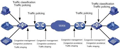
As shown in the figure above, traffic classification, traffic policing, traffic shaping, congestion management, and congestion avoidance are the foundations for a network to provide differentiated services. They are described as follow:
l Traffic classification identifies traffic based on certain matching rules. It is a prerequisite for differentiated services and is usually applied in the inbound direction of a port.
l Traffic policing confines traffic to a specific specification and is usually applied in the inbound direction of a port. You can configure restriction or penalty measures against the exceeding traffic to protect carrier benefits and network resources.
l Traffic shaping adapts output traffic rate usually to the input capability of the receiving device to avoid packet drop and port congestion. Traffic shaping is usually applied in the outbound direction of a port.
l Congestion management handles resource competition during network congestion. Generally, it adds packets to queues first, and then forwards the packets by using a scheduling algorithm. Congestion management is usually applied in the outbound direction of a port.
l Congestion avoidance monitors the use of network resources and drops packets actively when congestion reaches certain degree. It relieves network load by adjusting traffics. Congestion avoidance is usually applied in the outbound direction of a port.
Traffic classification is the basis of all the above-mentioned traffic management technologies. It identifies packets using certain rules and makes differentiated services possible. Traffic policing, traffic shaping, congestion management, and congestion avoidance are methods for implementing network traffic control and network resource management. They are occurrences of differentiated services.
QoS Supported By S3600 Series Ethernet Switches
The S3600 series Ethernet switches support the QoS features listed in Table 1-1:
Table 1-1 QoS features supported by S3600 series Ethernet switches
|
QoS Feature |
Description |
Refer to … |
|
Traffic classification |
Classify incoming traffic based on ACLs. The S3600 series support the following types of ACLs: l Basic ACLs l Advanced ACLs l Layer-2 ACLs l User-defined ACLs |
l For information about ACLs, refer to the ACL Operation and ACL Command manuals. l For information about traffic classification, refer to Traffic Classification. |
|
QoS action |
The S3600 series support performing the following QoS actions for packets matching the specified ACL: l Priority marking l Traffic policing l Traffic redirecting l VLAN Mapping l Traffic accounting l Traffic mirroring |
l For information about priority marking, refer to Priority Marking. l For information about traffic policing, refer to Traffic Policing. l For information about traffic redirecting, refer to Traffic Redirecting. l For information about VLAN Mapping, refer to VLAN Mapping. l For information about traffic accounting, refer to Flow-based Traffic Accounting. l For information about traffic mirroring, refer to Traffic mirroring. |
|
You can configure the following QoS actions as required on the S3600 series: l Priority trust mode l Protocol packer priority l Line rate l Burst |
l For information about priority trust mode, refer to Priority Trust Mode. l For information about specifying priority for protocol packets, refer to Protocol Priority. l For information about line rate, refer toLine Rate. l For information about the burst function, refer to Burst. |
|
|
Congestion avoidance |
WRED |
For information about congestion avoidance and WRED, refer to Congestion Avoidance. |
|
Congestion management |
The S3600 series support SP, WFQ, and WRR queue scheduling algorithms and support the following five queue scheduling modes: l SP l WFQ l WRR l SP+WFQ l SP+WRR |
For information about SP, WFQ, and WRR, refer to Queue Scheduling. |
Introduction to QoS Functions
Traffic Classification
Traffic here refers to service traffic; that is, all the packets passing the switch.
Traffic classification means identifying packets that conform to certain characteristics according to certain rules. It is the foundation for providing differentiated services.
In traffic classification, the priority bit in the type of service (ToS) field in IP packet header can be used to identify packets of different priorities. The network administrator can also define traffic classification policies to identify packets by the combination of source address, destination address, MAC address, IP protocol or the port number of an application. Normally, traffic classification is done by checking the information carried in packet header. Packet payload is rarely adopted for traffic classification. The identifying rule is unlimited in range. It can be a quintuplet consisting of source address, source port number, protocol number, destination address, and destination port number. It can also be simply a network segment.
Priority Trust Mode
Introduction to precedence types
1) IP precedence, ToS precedence, and DSCP precedence
Figure 1-2 DS field and ToS byte
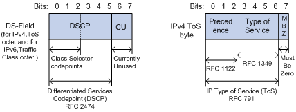
The ToS field in an IP header contains eight bits numbered 0 through 7, among which,
l The first three bits indicate IP precedence in the range 0 to 7.
l Bit 3 to bit 6 indicate ToS precedence in the range of 0 to 15.
l In RFC2474, the ToS field in IP packet header is also known as DS field. The first six bits (bit 0 through bit 5) of the DS field indicate differentiated service codepoint (DSCP) in the range of 0 to 63, and the last two bits (bit 6 and bit 7) are reserved.
Table 1-2 Description on IP Precedence
|
IP Precedence (decimal) |
IP Precedence (binary) |
Description |
|
0 |
000 |
Routine |
|
1 |
001 |
priority |
|
2 |
010 |
immediate |
|
3 |
011 |
flash |
|
4 |
100 |
flash-override |
|
5 |
101 |
critical |
|
6 |
110 |
internet |
|
7 |
111 |
network |
In a network providing differentiated services, traffics are grouped into the following four classes, and packets are processed according to their DSCP values.
l Expedited Forwarding (EF) class: In this class, packets can be forwarded regardless of link share of other traffic. The class is suitable for preferential services with low delay, low packet loss ratio, low jitter, and assured bandwidth (such as virtual leased line);
l Assured forwarding (AF) class: This class is further divided into four subclasses (AF1/2/3/4) and a subclass is further divided into three drop priorities, so the AF service level can be segmented. The QoS rank of the AF class is lower than that of the EF class;
l Class selector (CS) class: This class comes from the IP ToS field and includes eight subclasses;
Table 1-3 Description on DSCP precedence values
|
DSCP value (decimal) |
DSCP value (binary) |
Description |
|
46 |
101110 |
ef |
|
10 |
001010 |
af11 |
|
12 |
001100 |
af12 |
|
14 |
001110 |
af13 |
|
18 |
010010 |
af21 |
|
20 |
010100 |
af22 |
|
22 |
010110 |
af23 |
|
26 |
011010 |
af31 |
|
28 |
011100 |
af32 |
|
30 |
011110 |
af33 |
|
34 |
100010 |
af41 |
|
36 |
100100 |
af42 |
|
38 |
100110 |
af43 |
|
8 |
001000 |
cs1 |
|
16 |
010000 |
cs2 |
|
24 |
011000 |
cs3 |
|
32 |
100000 |
cs4 |
|
40 |
101000 |
cs5 |
|
48 |
110000 |
cs6 |
|
56 |
111000 |
cs7 |
|
0 |
000000 |
be (default) |
802.1p priority lies in Layer 2 packet headers and is applicable to occasions where the Layer 3 packet header does not need analysis but QoS must be assured at Layer 2.
Figure 1-3 An Ethernet frame with an 802.1Q tag header
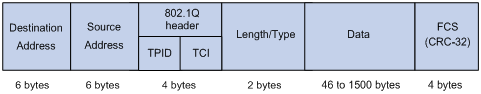
As shown in the figure above, the 4-byte 802.1Q tag header consists of the tag protocol identifier (TPID, two bytes in length), whose value is 0x8100, and the tag control information (TCI, two bytes in length). Figure 1-4 describes the detailed contents of an 802.1Q tag header.
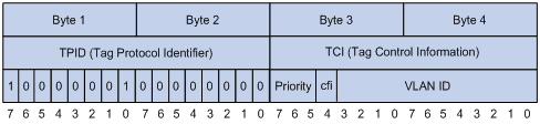
In the figure above, the priority field (three bits in length) in TCI is 802.1p priority (also known as CoS precedence), which ranges from 0 to 7.
Table 1-4 Description on 802.1p priority
|
802.1p priority (decimal) |
802.1p priority (binary) |
Description |
|
0 |
000 |
best-effort |
|
1 |
001 |
background |
|
2 |
010 |
spare |
|
3 |
011 |
excellent-effort |
|
4 |
100 |
controlled-load |
|
5 |
101 |
video |
|
6 |
110 |
voice |
|
7 |
111 |
network-management |
The precedence is called 802.1p priority because the related applications of this precedence are defined in detail in the 802.1p specifications.
3) Local precedence
Local precedence is a locally significant precedence that the device assigns to a packet. A local precedence value corresponds to one of the eight hardware output queues. Packets with the highest local precedence are processed preferentially. As local precedence is used only for internal queuing, a packet does not carry it after leaving the queue.
Priority trust mode
After a packet enters a switch, the switch sets the 802.1p priority and local precedence for the packet according to its own capability and the corresponding rules.
1) For a packet carrying no 802.1q tag
When a packet carrying no 802.1q tag reaches the port of a switch, the switch uses the port priority as the 802.1p precedence value of the received packet, searches for the local precedence corresponding to the port priority of the receiving port in the 802.1p-to-local precedence mapping table, and assigns the local precedence to the packet.
2) For an 802.1q tagged packet
When an 802.1q tagged packet reaches the port of a switch, you can use the priority trust on the receiving port to configure the port to trust packet priority or use the priority command on the receiving port to configure the port to trust port priority. By default, port priority is trusted and the priority of a port is 0.
l Trusting port priority
In this mode, the switch replaces the 802.1p priority of the received packet with the port priority, searches for the local precedence corresponding to the port priority of the receiving port in the 802.1p-to-local precedence mapping table, and assigns the local precedence to the packet.
l Trusting packet priority
In this mode, the switch searches for the local precedence corresponding to the 802.1p priority of the packet in the 802.1p-to-local precedence mapping table and assigns the local precedence to the packet.
Table 1-5 shows the default 802.1p priority-to-local precedence mapping table. You can modify the default mapping tables at the CLI. For detailed configuration procedure, refer to Configuring the Mapping between 802.1p Priority and Local Precedence.
Table 1-5 802.1p priority-to-local precedence mapping table
|
802.1p priority |
Local precedence |
|
0 |
2 |
|
1 |
0 |
|
2 |
1 |
|
3 |
3 |
|
4 |
4 |
|
5 |
5 |
|
6 |
6 |
|
7 |
7 |
Protocol Priority
Protocol packets generated by a switch carry their own priority. You can set a new IP precedence or DSCP precedence for the specific type of protocol packets to implement QoS.
Priority Marking
l If 802.1p priority marking is configured, the traffic will be mapped to the local precedence corresponding to the re-marked 802.1p priority and assigned to the output queue corresponding to the local precedence.
l If local precedence marking is configured, the traffic will be assigned to the output queue corresponding to the re-marked local precedence.
l If IP precedence or DSCP marking is configured, the traffic will be marked with new IP precedence or DSCP precedence.
Traffic Policing
The network will be made more congested by plenty of continuous burst packets if the traffic of each user is not limited. The traffic of each user must be limited in order to make better use of the limited network resources and provide better service for more users. For example, traffic can be limited to get only its committed resources during a time period to avoid network congestion caused by excessive bursts.
Traffic policing is a kind of traffic control policy used to limit the traffic and the resource occupied by supervising the traffic. The regulation policy is implemented according to the evaluation result on the premise of knowing whether the traffic exceeds the specification when traffic policing is performed. Normally, token bucket is used for traffic evaluation.
Token bucket
The token bucket can be considered as a container with a certain capacity to hold tokens. The system puts tokens into the bucket at the set rate. When the token bucket is full, the extra tokens will overflow and the number of tokens in the bucket stops increasing.
Figure 1-5 Evaluate the traffic with the token bucket
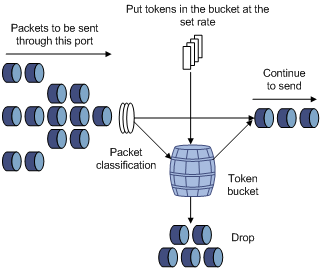
Evaluating the traffic with the token bucket
When token bucket is used for traffic evaluation, the number of the tokens in the token bucket determines the amount of the packets that can be forwarded. If the number of tokens in the bucket is enough to forward the packets, the traffic is conforming to the specification; otherwise, the traffic is nonconforming or excess.
Parameters concerning token bucket include:
l Average rate: The rate at which tokens are put into the bucket, namely, the permitted average rate of the traffic. It is generally set to committed information rate (CIR).
l Burst size: The capacity of the token bucket, namely, the maximum traffic size that is permitted in each burst. It is generally set to committed burst size (CBS). The set burst size must be greater than the maximum packet length.
One evaluation is performed on each arriving packet. In each evaluation, if the number of tokens in the bucket is enough, the traffic is conforming to the specification and you must take away some tokens whose number is corresponding to the packet forwarding authority; if the number of tokens in the bucket is not enough, it means that too many tokens have been used and the traffic is excess.
Traffic policing
The typical application of traffic policing is to supervise specific traffic into the network and limit it to a reasonable range, or to "discipline" the extra traffic. In this way, the network resources and the interests of the operators are protected. For example, you can limit HTTP packets to be within 50% of the network bandwidth. If the traffic of a certain connection is excess, traffic policing can choose to drop the packets or to reset the priority of the packets.
Traffic policing is widely used in policing the traffic into the network of internet service providers (ISPs). Traffic policing can identify the policed traffic and perform pre-defined policing actions based on different evaluation results. These actions include:
l Drop. Drop the packet whose evaluation result is “nonconforming”.
l Modify the DSCP precedence and forward. Modify the DSCP precedence of the packets whose evaluation result is “nonconforming” and then forward them.
Line Rate
Line rate refers to limiting the total rate of inbound or outbound packets on a port.
Line rate can be implemented through token buckets. That is, if you perform line rate configuration for a port, the token bucket determines the way to process the packets to be sent by this port or packets reaching the port. Packets can be sent or received if there are enough tokens in the token bucket; otherwise, they will be dropped.
Compared to traffic policing, line rate applies to all the packets passing a port. It is a simpler solution if you want to limit the rate of all the packets passing a port.
Traffic Redirecting
Traffic redirecting identifies traffic using ACLs and redirects the matched packets to CPU, the specified ports/aggregation group. By traffic redirecting, you can change the way in which a packet is forwarded to achieve specific purposes.
VLAN Mapping
VLAN mapping identifies traffics using ACLs and maps the VLAN tags carrier in matched packets to specific VLAN tags. By employing VLAN mapping on a switch connecting user networks to the carrier network, you can map the VLAN tags of specific user network packets to those of specific VLANs in the carrier network, thus meeting the requirements of the carrier network.
Queue Scheduling
When the network is congested, the problem that many packets compete for resources must be solved, usually through queue scheduling.
1) SP queuing
Figure 1-6 Diagram for SP queuing
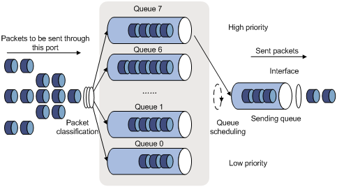
SP queue-scheduling algorithm is specially designed for critical service applications. An important feature of critical services is that they demand preferential service in congestion in order to reduce the response delay. Assume that there are eight output queues on the port and the preferential queue classifies the eight output queues on the port into eight classes, which are queue7, queue6, queue5, queue4, queue3, queue2, queue1, and queue0. Their priorities decrease in order.
In queue scheduling, SP sends packets in the queue with higher priority strictly following the priority order from high to low. When the queue with higher priority is empty, packets in the queue with lower priority are sent. You can put critical service packets into the queues with higher priority and put non-critical service (such as e-mail) packets into the queues with lower priority. In this case, critical service packets are sent preferentially and non-critical service packets are sent when critical service groups are not sent.
2) WFQ queuing
Figure 1-7 Diagram for WFQ queuing
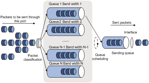
Before WFQ is introduced, you must understand fair queuing (FQ) first. FQ is designed for the purpose of sharing network resources fairly and optimizing the delays and delay jitters of all the flows. It takes the interests of all parties into account, such as:
l Different queues are scheduled fairly, so the delay of each flow is balanced globally.
l Both short and long packets are scheduled fairly. When there are multiple long packets and short packets to be sent among different queues, the short packets must be scheduled preferentially, so that the delay jitters of packets of each flow is reduced globally.
Compared with FQ, WFQ takes the priority into account when calculating the scheduling sequence of packets. Statistically speaking, WFQ assigns more scheduling chances to high priority packets than those to low priority packets. WFQ can classify the traffic automatically according to the session information of traffic including the protocol types, source and destination TCP or UDP port numbers, source and destination IP addresses, and priority values in the ToS field. WFQ also provide as many queues as possible to accommodate each flow evenly. Thus, the delay of each flow is balanced globally. When the packets dequeue, WFQ assigns the bandwidth to each flow on the egress according to the traffic precedence or DSCP precedence. The lower the traffic precedence is, the less bandwidth the traffic gets. The higher the traffic precedence is, the more bandwidth the traffic gets. Finally, each queue is polled and the corresponding number of packets is taken out to be sent according to the proportion of bandwidth.
You can use the WFQ algorithm to assign bandwidth to the output queues of a port, and then decide which queue a traffic flows into according to the mapping between the COS value of the traffic and the queue, and also deicide how much bandwidth is to be assigned to each traffic.
3) WRR queuing
Figure 1-8 Diagram for WRR queuing
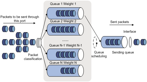
WRR queue-scheduling algorithm schedules all the queues in turn and every queue can be assured of a certain service time.
In a typical H3C switch there are eight output queues on each port. WRR configures a weight value for each queue, for example: w7, w6, w5, w4, w3, w2, w1, and w0 respectively for queue 7 through queue 0. A weight value indicates the proportion of resources available for a queue. On a 100-Mbps port, configure the weight value of WRR queue-scheduling algorithm to 5, 5, 3, 3, 1, 1, 1, and 1 (corresponding to w7, w6, w5, w4, w3, w2, w1, and w0 in order). In this way, the queue with the lowest priority can get 5 Mbps (100 Mbps × 1/(5+5+3+3+1+1+1+1)) bandwidth at least, and the disadvantage of SP queue-scheduling that the packets in queues with lower priority may not get service for a long time is avoided. Another advantage of WRR queue is that: though the queues are scheduled in order, the service time for each queue is not fixed; that is to say, if a queue is empty, the next queue will be scheduled. In this way, the bandwidth resources are made full use.
Congestion Avoidance
Congestion may cause network resource unavailable and thus need to be prevented. As a type of flow control mechanism, congestion avoidance aims to relieve network load through traffic adjusting. With congestion avoidance configuration performed, packets are dropped in advance when the utilization of certain network resources (such as output queues or buffer created in the memory) reaches certain degree.
Traditional packet dropping policy
Tail drop is adopted in traditional packet drop policies. It drops all the newly arrived packets when the current queue length reaches a specific value.
Such a policy will result in global TCP connection synchronization. If a queue drops packets of multiple TCP connections simultaneously, the TCP connections will turn to the state of congestion avoidance and slow startup for the traffics to be regulated. The traffic peak will then occur in a certain future time. Consequently, the network traffic jitters all the time.
WRED
You can use weighted random early detection (WRED) to avoid global TCP session synchronization.
In WRED algorithm, an upper limit and a lower limit are set for each queue, and the packets in a queue are processed as follows.
l When the current queue length is smaller than the lower limit, no packet is dropped;
l When the queue length exceeds the upper limit, all the newly received packets are dropped;
l When the queue length is between the lower limit and the upper limit, the newly received packets are dropped at random. The longer the queue, the more likely the newly received packets may be dropped. However, a maximum drop probability exists.
In WRED, random numbers are generated to determine the packets to be dropped. As the dropping policy is determined by IP precedence, packets with lower precedence are more likely to be dropped.
WRED prevents global TCP session synchronization. It enables other TCP sessions to be free of a TCP session slowed down because of its packets being dropped. In this way, TCP sessions can operate in different rates in any case and the link bandwidth can be fully utilized.
Flow-based Traffic Accounting
The function of flow-based traffic accounting is to use ACL rules in traffic classification and perform traffic accounting on the packets matching the ACL rules. You can get the statistics of the packets you are interested in through this function.
Burst
The Burst function can provide better packet cache function and traffic forwarding performance. It is suitable for networks where
l Large amount of broadcast/multicast packets and large burst traffic exist.
l Packets of high-rate links are forwarded to low-rate links or packets of multiple links with the equal rates are forwarded to a single link that is of the same rate as that of the incoming links.
Although the burst function helps reduce the packet loss ratio and improve packet processing capability in the networks mentioned above, it may affect QoS performance. So, use this function with caution.
Traffic mirroring
Traffic mirroring identifies traffic using ACLs and duplicates the matched packets to the destination mirroring port or CPU depending on your configuration. For information about port mirroring, refer to the Mirroring module of this manual.
QoS Configuration
Complete the following tasks to configure QoS:
|
Task |
Remarks |
|
Optional |
|
|
Configuring the Mapping between 802.1p Priority and Local Precedence |
Optional |
|
Optional |
|
|
Optional |
|
|
Optional |
|
|
Optional |
|
|
Optional |
|
|
Optional |
|
|
Optional |
|
|
Optional |
|
|
Optional |
|
|
Optional |
|
|
Optional |
Configuring Priority Trust Mode
Refer to section Priority Trust Mode for introduction to priority trust mode.
Configuration prerequisites
l The priority trust mode to be adopted has been determined.
l The port where priority trust mode is to be configured has been determined.
l The port priority value has been determined.
Configuration procedure
Follow these steps to configure to trust port priority:
|
To do… |
Use the command… |
Remarks |
|
Enter system view |
system-view |
— |
|
Enter Ethernet port view |
interface interface-type interface-number |
— |
|
Configure to trust port priority and configure the port priority |
priority priority-level |
Optional By default, the switch trusts port priority and the priority of a port is 0. |
Follow these steps to configure to trust packet priority:
|
To do… |
Use the command… |
Remarks |
|
Enter system view |
system-view |
— |
|
Enter Ethernet port view |
interface interface-type interface-number |
— |
|
Configure to trust packet priority |
priority trust |
Required By default, the switch trusts port priority. |
Configuration example
l Configure to trust port priority on Ethernet 1/0/1 and set the priority of Ethernet 1/0/1 to 7.
Configuration procedure:
<Sysname> system-view
[Sysname] interface Ethernet1/0/1
[Sysname-Ethernet1/0/1] priority 7
l Configure to trust packet priority on Ethernet 1/0/2.
Configuration procedure:
<Sysname> system-view
[Sysname] interface Ethernet1/0/2
[Sysname-Ethernet1/0/2] priority trust
Configuring the Mapping between 802.1p Priority and Local Precedence
When the default mapping between 802.1p priority and local precedence cannot satisfy your requirements, you can modify the mapping at the CLI, thus modifying the mapping between 802.1p priority and the output queues and assigning packets with different priorities to the corresponding output queues.
Note that, this is a global setting, not a per port setting. This is only recommended for advanced network environments.
Configuration prerequisites
The mapping between 802.1p priority and local precedence has been determined.
Configuration procedure
Follow these steps to configure the mapping between 802.1p priority and local precedence:
|
To do… |
Use the command… |
Remarks |
|
Enter system view |
system-view |
— |
|
Configure the mapping between 802.1p priority and local precedence |
qos cos-local-precedence-map cos0-map-local-prec cos1-map-local-prec cos2-map-local-prec cos3-map-local-prec cos4-map-local-prec cos5-map-local-prec cos6-map-local-prec cos7-map-local-prec |
Required |
Configuration example
l Configure the following mapping between 802.1p priority and local precedence: 0 to 2, 1 to 3, 2 to 4, 3 to 1, 4 to 7, 5 to 0, 6 to 5, and 7 to 6.
l Display the configuration.
Configuration procedure:
<Sysname> system-view
[Sysname] qos cos-local-precedence-map 2 3 4 1 7 0 5 6
[Sysname] display qos cos-local-precedence-map
cos-local-precedence-map:
cos(802.1p) : 0 1 2 3 4 5 6 7
--------------------------------------------------------------------------
local precedence(queue) : 2 3 4 1 7 0 5 6
Setting the Priority of Protocol Packets
Refer to section Protocol Priority for information about priority of protocol packets.
Configuration prerequisites
l The protocol type has been determined.
l The priority type (IP or DSCP) and priority value have been determined.
Configuration procedure
Follow these steps to set the priority for specific protocol packets:
|
To do… |
Use the command… |
Remarks |
|
Enter system view |
system-view |
— |
|
Set the priority for specific protocol packets |
protocol-priority protocol-type protocol-type { ip-precedence ip-precedence | dscp dscp-value } |
Required You can modify the IP precedence or DSCP precedence of the corresponding protocol packets. |
![]()
l On an S3600-EI switch, you can set the priority for protocol packets of Telnet, OSPF, SNMP, and ICMP.
l On an S3600-SI switch, you can set the priority for protocol packets of Telnet, SNMP, and ICMP.
Configuration example
l Set the IP precedence of ICMP packets to 3.
l Display the configuration.
Configuration procedure:
<Sysname> system-view
[Sysname] protocol-priority protocol-type icmp ip-precedence 3
[Sysname] display protocol-priority
Protocol: icmp
IP-Precedence: flash(3)
Marking Packet Priority
Refer to section Priority Marking for information about marking packet priority.
Marking packet priority can be implemented in the following two ways:
l Through traffic policing
When configuring traffic policing, you can define the action of marking the DSCP precedence for packets exceeding the traffic specification. Refer to section Configuring Traffic Policing.
l Through the traffic-priority command
You can use the traffic priority command to mark the IP precedence, 802.1p priority, DSCP precedence, and local precedence of the packets.
Configuration prerequisites
The following items are defined or determined before the configuration:
l The ACL rules used for traffic classification have been specified. Refer to the ACL module of this manual for related information.
l The type and value of the precedence to be marked for the packets matching the ACL rules have been determined.
l The port or VLAN on which the configuration is to be performed has been determined.
Configuration procedure
Follow these steps to configure priority marking on a port:
|
To do… |
Use the command… |
Remarks |
|
Enter system view |
system-view |
— |
|
Enter Ethernet port view |
interface interface-type interface-number |
— |
|
Mark the priorities for packets matching specific ACL rules |
traffic-priority { inbound | outbound } acl-rule { { dscp dscp-value | ip-precedence { pre-value | from-cos } } | cos { pre-value | from-ipprec } | local-precedence pre-value }* |
Required Refer to the command manual for information about the acl-rule argument. |
Follow these steps to configure priority marking on a VLAN:
|
To do… |
Use the command… |
Remarks |
|
Enter system view |
system-view |
— |
|
Mark the priorities for the packets belonging to a VLAN and matching specific ACL rules |
traffic-priority vlan vlan-id { inbound | outbound } acl-rule { { dscp dscp-value | ip-precedence { pre-value | from-cos } } | cos { pre-value | from-ipprec } | local-precedence pre-value }* |
Required Refer to the command manual for information about the acl-rule argument. |
Configuration example
l Ethernet 1/0/1 belongs to VLAN 2 and is connected to the 10.1.1.1/24 network segment.
l Mark the DSCP precedence as 56 for the packets from the 10.1.1.1/24 network segment.
1) Method I
<Sysname> system-view
[Sysname] acl number 2000
[Sysname-acl-basic-2000] rule permit source 10.1.1.0 0.0.0.255
[Sysname-acl-basic-2000] quit
[Sysname] interface Ethernet1/0/1
[Sysname-Ethernet1/0/1] traffic-priority inbound ip-group 2000 dscp 56
2) Method II
<Sysname> system-view
[Sysname] acl number 2000
[Sysname-acl-basic-2000] rule permit source 10.1.1.0 0.0.0.255
[Sysname-acl-basic-2000] quit
[Sysname] traffic-priority vlan 2 inbound ip-group 2000 dscp 56
Configuring Traffic Policing
Refer to section Traffic Policing for information about traffic policing.
Configuration prerequisites
l The ACL rules used for traffic classification have been defined. Refer to the ACL module of this manual for information about defining ACL rules.
l The rate limit for traffic policing, and the actions for the packets exceeding the rate limit have been determined.
l The ports that need this configuration have been determined.
Configuration procedure
Follow these steps to configure traffic policing:
|
To do… |
Use the command… |
Remarks |
|
Enter system view |
system-view |
— |
|
Enter Ethernet port view |
interface interface-type interface-number |
— |
|
Configure traffic policing |
traffic-limit inbound acl-rule [ union-effect ] [ egress-port interface-type interface-number ] target-rate [ burst-bucket burst-bucket-size ] [ exceed action ] |
Required Specify a committed information rate (CIR) for the target-rate argument, and specify a committed bust size (CBS) for the burst-bucket-size argument. By default, traffic policing is disabled. |
![]()
The granularity of traffic policing is 64 Kbps. If the number you input is in the range of N*64 to (N+1)*64 (N is a natural number), it will be rounded off to (N+1)*64.
Configuration example
l Ethernet 1/0/1 of the switch is connected to the 10.1.1.0/24 network segment
l Perform traffic policing on the packets from the 10.1.1.0/24 network segment, setting the rate to 128 kbps
l Mark the DSCP precedence as 56 for the inbound packets exceeding the rate limit.
Configuration procedure:
<Sysname> system-view
[Sysname] acl number 2000
[Sysname-acl-basic-2000] rule permit source 10.1.1.0 0.0.0.255
[Sysname-acl-basic-2000] quit
[Sysname] interface Ethernet1/0/1
[Sysname-Ethernet1/0/1] traffic-limit inbound ip-group 2000 128 exceed remark-dscp 56
Configuring Line Rate
Refer to section Line Rate for information about line rate.
Configuration prerequisites
l The port on which line rate configuration is to be performed has been determined.
l The target rate and the direction of rate limiting (inbound or outbound) have been determined.
Configuration procedure
Follow these steps to configure line rate:
|
To do… |
Use the command… |
Remarks |
|
Enter system view |
system-view |
— |
|
Enter Ethernet port view |
interface interface-type interface-number |
— |
|
Configure line rate |
line-rate { inbound | outbound } target-rate [ burst-bucket burst-bucket-size ] |
Required Specify a committed information rate (CIR) for the target-rate argument, and specify a committed bust size (CBS) for the burst-bucket-size argument. By default, line rate is disabled. |
Configuration example
l Configure line rate for outbound packets on Ethernet 1/0/1.
l The rate limit is 1,024 Kbps
Configuration procedure:
<Sysname> system-view
[Sysname] interface Ethernet1/0/1
[Sysname-Ethernet1/0/1] line-rate outbound 1024
Configuring Traffic Redirecting
Refer to section Traffic Redirecting for information about traffic redirecting.
Configuration prerequisites
l The ACL rules used for traffic classification have been defined. Refer to the ACL module of this manual for information about defining ACL rules.
l The traffic redirecting destination has been determined.
l The ports that need this configuration have been determined.
Configuration procedure
Follow these steps to configure traffic redirecting:
|
To do… |
Use the command… |
Remarks |
|
Enter system view |
system-view |
— |
|
Enter Ethernet port view |
interface interface-type interface-number |
— |
|
Configure traffic redirecting |
traffic-redirect { inbound | outbound } acl-rule { cpu | { interface interface-type interface-number | link-aggregation-group agg-id } [ untagged ] } |
Required By default, traffic redirecting is not configured. |
![]()
l Packets redirected to the CPU are not forwarded.
l If the traffic is redirected to a Combo port in down state, the system automatically redirects the traffic to the port corresponding to the Combo port in up state. Refer to the Port Basic Configuration module of this manual for information about Combo ports.
l If the traffic is configured to be redirected to an aggregation group, the traffic is redirected to the master port of the aggregation group. Refer to the Link Aggregation module of this manual for information about aggregation group.
l When the traffic redirecting function is used in conjunction with the selective QinQ function, you can specify the untagged keyword as required (that is, remove the outer VLAN tag of a packet after the packet is redirected to the uplink port) in a tree network with a single uplink port (or an aggregation group). Do not specify the untagged keyword in a ring network or a network with multiple uplink ports. Refer to the VLAN-VPN module of this manual for information about selective QinQ.
Configuration example
l Ethernet 1/0/1 is connected to the 10.1.1.0/24 network segment.
l Redirect all the packets from the 10.1.1.0/24 network segment to Ethernet 1/0/7.
Configuration procedure:
<Sysname> system-view
[Sysname] acl number 2000
[Sysname-acl-basic-2000] rule permit source 10.1.1.0 0.0.0.255
[Sysname-acl-basic-2000] quit
[Sysname] interface Ethernet1/0/1
[Sysname-Ethernet1/0/1] traffic-redirect inbound ip-group 2000 interface Ethernet1/0/7
Configuring VLAN Mapping
Refer to section VLAN Mapping for information about VLAN mapping.
Configuration prerequisites
l The ACL rules used for traffic classification have been defined. Refer to the ACL module of this manual for information about defining ACL rules.
l The ports on which the configuration is to be performed have been determined.
l The VLAN ID to be set for the packets has been determined.
Configuration procedure
Follow these steps to configure VLAN mapping:
|
Use the command… |
Remarks |
|
|
Enter system view |
system-view |
— |
|
Enter Ethernet port view |
interface interface-type interface-number |
— |
|
Configure VLAN mapping |
traffic-remark-vlanid inbound acl-rule remark-vlan remark-vlanid |
Required By default, VLAN mapping is not configured. |
Configuring Queue Scheduling
Refer to section Queue Scheduling for information about queue scheduling.
Configuration prerequisites
The algorithm for queue scheduling to be used and the related parameters have been determined.
Configuration procedure
Follow these steps to configure queue scheduling in system view:
|
To do… |
Use the command… |
Remarks |
|
Enter system view |
system-view |
— |
|
Configure queue scheduling |
queue-scheduler { strict-priority | wfq queue0-width queue1-width queue2-width queue3-width queue4-width queue5-width queue6-width queue7-width | wrr queue0-weight queue1-weight queue2-weight queue3-weight queue4-weight queue5-weight queue6-weight queue7-weight } |
Required By default, the queue scheduling algorithm adopted on all the ports is WRR. The default weights of the eight output queues of a port are 1, 2, 3, 4, 5, 9, 13, and 15 (in the order queue 0 through queue 7). |
Follow these steps to configure queue scheduling in Ethernet port view:
|
To do… |
Use the command… |
Remarks |
|
Enter system view |
system-view |
— |
|
Enter Ethernet port view |
interface interface-type interface-number |
— |
|
Configure queue scheduling |
queue-scheduler { wfq queue0-width queue1-width queue2-width queue3-width queue4-width queue5-width queue6-width queue7-width | wrr queue0-weight queue1-weight queue2-weight queue3-weight queue4-weight queue5-weight queue6-weight queue7-weight } |
Required By default, the queue scheduling algorithm adopted on all the ports is WRR. The default weights of the eight output queues of a port are 1, 2, 3, 4, 5, 9, 13, and 15 (in the order queue 0 through queue 7). |
A port of an S3600 Ethernet switch supports eight output queues. These queue scheduling algorithms are available: SP, WRR, and WFQ. With WRR (or WFQ) adopted, if you set the weight or the bandwidth of one or multiple queues to 0, the switch will add the queue or these queues to the SP group, where SP is adopted. For other queues, WRR (or WFQ) still applies. In this case, both SP and WRR (or WFQ) are adopted.
In cases where both SP and WRR (or WFQ) queue scheduling algorithms are adopted, the queues in the SP group take precedence over other queues. For example, if queue 0, queue 1, queue 2, and queue 3 are in the SP group, queue 4, queue 5, queue 6, and queue 7 are scheduled using WRR (or WFQ), the switch will schedule the queues in the SP group preferentially by using the SP algorithm. Then queues outside the SP group are scheduled by using WRR (or WFQ) algorithm only when all the queues in the SP group are empty.
![]()
l The queue scheduling algorithm specified by using the queue-scheduler command in system view takes effect on all the ports. The queue scheduling algorithm configured in port view must be the same as that configured in system view. Otherwise, the system prompts configuration errors.
l If the weight (or bandwidth value) specified in system view for a queue of WRR queuing or WFQ queuing cannot meet the requirement of a port, you can modify the weight (or bandwidth value) for this port in the corresponding Ethernet port view. The new weight (or bandwidth value) takes effect only on the port.
l If the weight (or bandwidth value) specified in system view for a queue of SP-WRR queuing or SP-WFQ queuing in the command cannot meet the requirement of a port, you can modify the weight (or bandwidth value) for this port in the corresponding Ethernet port view. The new weight (or bandwidth value) takes effect only on the port.
l The display queue-scheduler command cannot display the queue weight (or bandwidth value) specified in Ethernet port view.
Configuration example
l Adopts WRR for queue scheduling, setting the weights of the output queues to 2, 2, 3, 3, 4, 4, 5, and 5 (in the order queue 0 through queue 7).
l Verify the configuration.
Configuration procedure:
<Sysname> system-view
[Sysname] queue-scheduler wrr 2 2 3 3 4 4 5 5
[Sysname] display queue-scheduler
Queue scheduling mode: weighted round robin
weight of queue 0: 2
weight of queue 1: 2
weight of queue 2: 3
weight of queue 3: 3
weight of queue 4: 4
weight of queue 5: 4
weight of queue 6: 5
weight of queue 7: 5
Configuring WRED
Refer to section Congestion Avoidance for information about WRED.
Configuration prerequisites
l The indexes of queues to be dropped at random, the queue length that starts the drop action, and the drop probability have been determined.
l The ports that need this configuration have been determined.
Configuration procedure
Follow these steps to configure WRED:
|
To do… |
Use the command… |
Remarks |
|
Enter system view |
system-view |
— |
|
Enter Ethernet port view |
interface interface-type interface-number |
— |
|
Configure WRED |
wred queue-index qstart probability |
Required By default, WRED is not configured. |
Configuration example
Configure WRED for queue 2 of Ethernet 1/0/1 to drop the packets in queue 2 randomly when the number of packets in queue 2 exceeds 64, setting the dropping probability being 20%.
Configuration procedure:
<Sysname> system-view
[Sysname] interface Ethernet1/0/1
[Sysname-Ethernet1/0/1] wred 2 64 20
Configuring Traffic Accounting
Refer to section Flow-based Traffic Accounting for information about traffic accounting.
Configuration prerequisites
l The ACL rules for traffic classification have been defined. Refer to the ACL module of this manual for information about defining ACL rules.
l The port that needs this configuration has been determined.
Configuration procedure
Follow these steps to configure traffic accounting:
|
To do… |
Use the command… |
Remarks |
|
Enter system view |
system-view |
— |
|
Enter Ethernet port view |
interface interface-type interface-number |
— |
|
Configure traffic accounting |
traffic-statistic inbound acl-rule |
Required By default, traffic accounting is disabled. |
|
Clear the traffic statistics |
reset traffic-statistic inbound acl-rule |
Required |
Configuration example
l Ethernet 1/0/1 is connected to the 10.1.1.0/24 network segment.
l Perform traffic accounting on the packets sourced from the 10.1.1.0/24 network segment.
l Clear the traffic statistics.
Configuration procedure:
<Sysname> system-view
[Sysname] acl number 2000
[Sysname-acl-basic-2000] rule permit source 10.1.1.0 0.0.0.255
[Sysname-acl-basic-2000] quit
[Sysname] interface Ethernet1/0/1
[Sysname-Ethernet1/0/1] traffic-statistic inbound ip-group 2000
[Sysname-Ethernet1/0/1] reset traffic-statistic inbound ip-group 2000
Enabling the Burst Function
Refer to section Burst for information about the burst function.
Configuration prerequisites
You have determined that the burst function is required.
Configuration procedure
Follow these steps to enable the burst function:
|
To do… |
Use the command… |
Remarks |
|
Enter system view |
system-view |
— |
|
Enable the burst function |
burst-mode enable |
Required By default, the burst function is disabled. |
![]()
With the IRF function enabled, do not enable the burst function. Otherwise, packets may be forwarded improperly. Refer to the IRF Fabric part for the detailed information about IRF.
Configuring Traffic Mirroring
Refer to section Traffic mirroring for information about traffic mirroring.
Configuration prerequisites
l The ACL rules for traffic classification have been defined. Refer to the ACL module of this manual for information about defining ACL rules.
l The source mirroring ports and mirroring direction have been determined.
l The destination mirroring port has been determined.
Configuration procedure
Follow these steps to configure traffic mirroring:
|
To do… |
Use the command… |
Remarks |
|
|
Enter system view |
system-view |
— |
|
|
Enter Ethernet port view |
interface interface-type interface-number |
— |
|
|
Configure the current port as a source mirroring port |
mirrored-to { inbound | outbound } acl-rule { monitor-interface | cpu } |
Required Omit the following steps if you redirect traffic to the CPU. Proceed to the following steps if you redirect traffic to a port. |
|
|
Quit to system view |
quit |
— |
|
|
Configure the specified port as the destination mirroring port |
In system view |
mirroring-group group-id monitor-port monitor-port-id |
Required Use either approach. |
|
In Ethernet port view |
interface interface-type interface-number |
||
|
monitor-port |
|||
![]()
For information about the mirroring-group monitor-port command and the monitor-port command, refer to the part talking about mirroring.
Configuration example
Network requirements:
l Ethernet 1/0/1 is connected to the 10.1.1.0/24 network segment.
l Duplicate the packets from network segment 10.1.1.0/24 to the destination mirroring port Ethernet 1/0/4.
Configuration procedure:
<Sysname> system-view
[Sysname] acl number 2000
[Sysname-acl-basic-2000] rule permit source 10.1.1.0 0.0.0.255
[Sysname-acl-basic-2000] quit
[Sysname] interface Ethernet1/0/4
[Sysname-Ethernet1/0/4] monitor-port
[Sysname-Ethernet1/0/4] quit
[Sysname] interface Ethernet1/0/1
[Sysname-Ethernet1/0/1] mirrored-to inbound ip-group 2000 monitor-interface
Displaying and Maintaining QoS
|
To do… |
Use the command… |
Remarks |
|
Display the mapping between 802.1p priority and local precedence |
display qos cos-local-precedence-map |
Available in any view |
|
Display the priority marking configuration |
display qos-interface { interface-type interface-number | unit-id } traffic-priority |
|
|
Display the protocol packet priority configuration |
display protocol-priority |
|
|
Display line rate configuration |
display qos-interface { interface-type interface-number | unit-id } line-rate |
|
|
Display traffic policing configuration |
display qos-interface { interface-type interface-number | unit-id } traffic-limit |
|
|
Display traffic redirecting configuration |
display qos-interface { interface-type interface-number | unit-id } traffic-redirect |
|
|
Display VLAN mapping configuration |
display qos-interface { interface-type interface-number | unit-id } traffic-remark-vlanid |
|
|
Display queue scheduling configuration |
display queue-scheduler |
|
|
Display traffic accounting configuration |
display qos-interface { interface-type interface-number | unit-id } traffic-statistic |
|
|
Display traffic mirroring configuration |
display qos-interface { interface-type interface-number | unit-id } mirrored-to |
|
|
Display all the QoS configuration |
display qos-interface { interface-type interface-number | unit-id } all |
QoS Configuration Examples
Configuration Example of Traffic policing and Line Rate
Network requirement
An enterprise network connects all the departments through an Ethernet switch. PC 1, with the IP address 192.168.0.1 belongs to the R&D department and is connected to Ethernet 1/0/1 of the switch. The marketing department is connected to Ethernet 1/0/2 of the switch.
Configure traffic policing and line rate to satisfy the following requirements:
l Set the maximum rate of outbound packets sourced from the marketing department to 64 kbps. Drop the packets exceeding the rate limit.
l Set the maximum rate of outbound IP packets sent by PC 1 in the R&D department to 640 kbps. Drop the packets exceeding the rate limit.
Network diagram
Figure 1-9 Network diagram for traffic policing and rate limiting configuration

Configuration procedure
1) Define an ACL for traffic classification.
# Create ACL 2000 and enter basic ACL view.
<Sysname> system-view
[Sysname] acl number 2000
# Define a rule for the packets with 192.168.0.1 as the source IP address.
[Sysname-acl-basic-2000] rule permit source 192.168.0.1 0
[Sysname-acl-basic-2000] quit
2) Configure traffic policing and rate limiting
# Set the maximum rate of outbound packets sourced from the marketing department to 64 kbps.
[Sysname] interface Ethernet1/0/2
[Sysname-Ethernet1/0/2] line-rate inbound 64
[Sysname-Ethernet1/0/2] quit
# Set the maximum rate of outbound IP packets sent by PC 1 in the R&D department to 640 kbps.
[Sysname] interface Ethernet1/0/1
[Sysname-Ethernet1/0/1] traffic-limit inbound ip-group 2000 640 exceed drop
Configuration Example of Priority Marking and Queue Scheduling
Network requirements
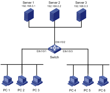
As shown in Figure 1-10, an enterprise network connects all the departments through an Ethernet switch. Clients PC 1 through PC 3 are connected to Ethernet 1/0/1 of the switch; clients PC 4 through PC 6 are connected to Ethernet 1/0/3 of the switch. Server 1 (the database server), Server 2 (the mail server), and Server 3 (the file server) are connected to Ethernet 1/0/2 of the switch.
Configure priority marking and queue scheduling on the switch to mark traffic flows accessing Server 1, Server 2, and Server 3 with different priorities respectively and assign the three traffic flows to different queues for scheduling.
Network diagram
Figure 1-10 Network diagram for priority marking and queue scheduling configuration
Configuration procedure
1) Define an ACL for traffic classification
# Create ACL 3000 and enter advanced ACL view.
<Sysname> system-view
[Sysname] acl number 3000
# Define ACL rules for identifying packets based on destination IP addresses.
[Sysname-acl-adv-3000] rule 0 permit ip destination 192.168.0.1 0
[Sysname-acl-adv-3000] rule 1 permit ip destination 192.168.0.2 0
[Sysname-acl-adv-3000] rule 2 permit ip destination 192.168.0.3 0
[Sysname-acl-adv-3000] quit
2) Configure priority marking
# Mark priority for packets received through Ethernet 1/0/2 and matching ACL 3000.
[Sysname] interface Ethernet1/0/2
[Sysname-Ethernet1/0/2] traffic-priority inbound ip-group 3000 rule 0 local-precedence 4
[Sysname-Ethernet1/0/2] traffic-priority inbound ip-group 3000 rule 1 local-precedence 3
[Sysname-Ethernet1/0/2] traffic-priority inbound ip-group 3000 rule 2 local-precedence 2
[Sysname-Ethernet1/0/2] quit
3) Configure queue scheduling
# Apply SP queue scheduling algorithm.
[Sysname] queue-scheduler strict-priority
VLAN Mapping Configuration Example
Network requirements
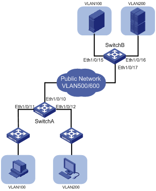
Two customer networks are connected to the public network through Switch A and Switch B. Configure the VLAN mapping function on the switches to enable the hosts on the two customer networks to communicate through public network VLANs.
l Switch A provides network access for terminal devices in VLAN 100 and VLAN 200 through Ethernet 1/0/11 and Ethernet 1/0/12. On the other side of the public network, Switch B provides network access for servers in VLAN 100 and VLAN 200 through Ethernet 1/0/15 and Ethernet 1/0/16.
l Switch A provides access to the public network through Ethernet 1/0/10 and Switch B provides access to the public network through Ethernet 1/0/17.
Configure the switches to have packets of VLAN 100 and packets of VLAN 200 transmitted in VLAN 500 and VLAN 600 across the public network.
Network diagram
Figure 1-11 Network diagram for VLAN mapping configuration
Configuration procedure
# Create customer VLANs VLAN 100 and VLAN 200 and service VLANs VLAN 500 and VLAN 600 on Switch A.
<SwitchA> system-view
[SwitchA] vlan 100
[SwitchA-vlan100] quit
[SwitchA] vlan 200
[SwitchA-vlan200] quit
[SwitchA] vlan 500
[SwitchA-vlan500] quit
[SwitchA] vlan 600
[SwitchA-vlan600] quit
# Configure Ethernet 1/0/11 of Switch A as a trunk port and configure its default VLAN as VLAN 100. Assign Ethernet 1/0/11 to VLAN 100 and VLAN 500. Configure Ethernet 1/0/12 in the same way.
[SwitchA] interface Ethernet 1/0/11
[SwitchA-Ethernet1/0/11] port link-type trunk
[SwitchA-Ethernet1/0/11] port trunk pvid vlan 100
[SwitchA-Ethernet1/0/11] port trunk permit vlan 100 500
[SwitchA-Ethernet1/0/11] quit
[SwitchA] interface Ethernet 1/0/12
[SwitchA-Ethernet1/0/12] port link-type trunk
[SwitchA-Ethernet1/0/12] port trunk pvid vlan 200
[SwitchA-Ethernet1/0/12] port trunk permit vlan 200 600
[SwitchA-Ethernet1/0/12] quit
# Configure Ethernet 1/0/10 of Switch A as a trunk port, and assign it to VLAN 100, VLAN 200, VLAN 500, and VLAN 600.
[SwitchA] interface Ethernet 1/0/10
[SwitchA-Ethernet1/0/10] port link-type trunk
[SwitchA-Ethernet1/0/10] port trunk permit vlan 100 200 500 600
[SwitchA-Ethernet1/0/10] quit
# Configure Layer-2 ACLs on Switch A. Configure ACL 4000 to permit packets from VLAN 100, ACL 4001 to permit packets from VLAN 200, ACL 4002 to permit packets from VLAN 500, and ACL 4003 to permit packets from VLAN 600.
[SwitchA] acl number 4000
[SwitchA-acl-ethernetframe-4000] rule permit source 100
[SwitchA] quit
[SwitchA] acl number 4001
[SwitchA-acl-ethernetframe-4001] rule permit source 200
[SwitchA] quit
[SwitchA] acl number 4002
[SwitchA-acl-ethernetframe-4002] rule permit source 500
[SwitchA] quit
[SwitchA] acl number 4003
[SwitchA-acl-ethernetframe-4003] rule permit source 600
[SwitchA] quit
# Configure VLAN mapping on Ethernet 1/0/11 to replace VLAN tag 100 with VLAN tag 500.
[SwitchA] interface Ethernet 1/0/11
[SwitchA-Ethernet1/0/11] traffic-remark-vlanid inbound link-group 4000 remark-vlan 500
[SwitchA-Ethernet1/0/11] quit
# Configure VLAN mapping on Ethernet 1/0/12 to replace VLAN tag 200 with VLAN tag 600.
[SwitchA] interface Ethernet 1/0/12
[SwitchA-Ethernet1/0/12] traffic-remark-vlanid inbound link-group 4001 remark-vlan 600
[SwitchA-Ethernet1/0/12] quit
# Configure VLAN mapping on Ethernet 1/0/10 to replace VLAN tag 500 with VLAN tag 100 and replace VLAN tag 600 with VLAN tag 200.
[SwitchA] interface Ethernet 1/0/10
[SwitchA-Ethernet1/0/10] traffic-remark-vlanid inbound link-group 4002 remark-vlan 100
[SwitchA-Ethernet1/0/10] traffic-remark-vlanid inbound link-group 4003 remark-vlan 200
[SwitchA-Ethernet1/0/10] quit
Define the same VLAN mapping rules on Switch B. The detailed configuration procedure is similar to that of Switch A and thus is omitted here.
Configuring Traffic Mirroring and Redirecting Traffic to a Port
Network Requirements
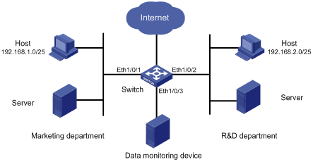
A company uses a switch to interconnect all the departments. As shown in Figure 1-12,
l The marketing department is connected to Ethernet 1/0/1 of the switch. The IP address segment for the hosts of the marketing department is 192.168.1.0/25, and the hosts access the Internet through the switch.
l The R&D department is connected to Ethernet 1/0/2 of the switch. The IP address segment for the hosts of the R&D department is 192.168.2.0/25, and the hosts access the Internet through the switch.
l The data monitoring device is connected to Ethernet 1/0/3 of the switch.
Configure traffic redirecting and traffic mirroring to satisfy the following requirements:
l From 8:00 to 18:00 in working days, mirror the HTTP traffic from the marketing department to the Internet to the data monitoring device.
l From 8:00 to 18:00 in working days, redirect the HTTP traffic from the R&D department to the Internet to the data monitoring device.
On the data monitoring device, the network administrator can analyze the HTTP traffic from each department to the Internet.
Network diagram
Figure 1-12 Network diagram for traffic redirecting and traffic mirroring configuration
Configuration procedure
1) Define a time range for working days
# Create a time range trname covering the period from 8:00 to 18:00 during working days.
<Switch> system-view
[Switch] time-range trname 8:00 to 18:00 working-day
2) Configure a policy for the traffic of the marketing department
# Create basic ACL 2000 to permit the traffic of the hosts in the marketing department during the specified time range.
[Switch] acl number 2000
[Switch-acl-basic-2000] rule permit source 192.168.1.0 0.0.0.127 time-range trname
[Switch-acl-basic-2000] quit
# Configure to mirror traffic matching ACL 2000 to Ethernet 1/0/3.
[Switch] interface ethernet 1/0/1
[Switch-Ethernet1/0/1] mirrored-to inbound ip-group 2000 monitor-interface
[Switch-Ethernet1/0/1] quit
[Switch] interface ethernet 1/0/3
[Switch-Ethernet1/0/3] monitor-port
[Switch-Ethernet1/0/3] quit
3) Configure a policy for the traffic of the R&D department
# Create basic ACL 2001 to permit the traffic of the hosts in the R&D department during the specified time range.
[Switch] acl number 2001
[Switch-acl-basic-2001] rule permit source 192.168.2.0 0.0.0.127 time-range trname
[Switch-acl-basic-2001] quit
# Configure to redirect traffic matching ACL 2001 to Ethernet 1/0/3.
[Switch] interface ethernet 1/0/2
[Switch-Ethernet1/0/2] traffic-redirect inbound ip-group 2001 interface Ethernet 1/0/3
When configuring QoS profile, go to these sections for information you are interested in:
l Overview
l QoS Profile Configuration Task List
l Displaying and Maintaining QoS Profile Configuration
Overview
Introduction to QoS Profile
QoS profile is a set of QoS configurations. It provides an easy way for performing and managing QoS configuration. A QoS profile can contain one or multiple QoS actions. In networks where hosts change their positions frequently, you can define QoS policies for the specific hosts and add the QoS policies to a QoS profile. When a host is connected to another port of a switch, you can simply apply the corresponding QoS profile to the port statically or dynamically to maintain the same QoS configuration performed for the host.
QoS Profile Application Mode
Dynamic application mode
A QoS profile can be applied dynamically to a user or a group of users passing 802.1x authentication. To apply QoS profiles dynamically, a user name-to-QoS profile mapping table is required on the AAA server. For a switch operating in this mode, after a user passes the 802.1x authentication, the switch looks up the user name-to-QoS profile mapping table for the QoS profile using the user name and then applies the QoS profile found to the port the user is connected to.
Corresponding to the 802.1x authentication modes, dynamic QoS profile application can be user-based and port-based.
l User-based QoS profile application
The switch generates a new QoS profile by adding user source MAC address information to the identifying rule defined in the existing QoS profile and then applies the new QoS profile to the port the user is connected to.
l Port-based QoS profile application
The switch directly applies the QoS profile to the port the user is connected to.
![]()
A user-based QoS profile application fails if the traffic classification rule defined in the QoS profile contains source address information (including source MAC address information, source IP address information, and VLAN information).
Manual application mode
You can use the apply command to manually apply a QoS profile to a port.
QoS Profile Configuration Task List
Complete the following tasks to configure QoS profile:
|
Operation |
Description |
|
Required |
|
|
Optional |
Configuring a QoS Profile
Configuration prerequisites
l The ACL rules used for traffic classification are defined. Refer to the ACL module of this manual for information about defining ACL rules.
l The type and number of actions in the QoS profile are specified.
Configuration procedure
Follow these steps to configure a QoS profile:
|
To do… |
Use the command… |
Remarks |
|
Enter system view |
system-view |
— |
|
Create a QoS profile and enter QoS profile view |
qos-profile profile-name |
Required If the specified QoS profile already exists, you enter the QoS profile view directly. |
|
Configure traffic policing |
traffic-limit inbound acl-rule [ union-effect ] [ egress-port interface-type interface-number ] target-rate [ burst-bucket burst-bucket-size ] [ exceed action ] |
Optional |
|
Configure packet filtering |
packet-filter { inbound | outbound } acl-rule |
Optional Refer to the ACL module of this manual for information about packet filtering. |
|
Configure priority marking |
traffic-priority { inbound | outbound } acl-rule { { dscp dscp-value | ip-precedence { pre-value | from-cos } } | cos { pre-value | from-ipprec } | local-precedence pre-value }* |
Optional |
Applying a QoS Profile
You can configure to apply a QoS profile dynamically or simply apply a QoS profile manually.
Configuration prerequisites
l To configure to apply a QoS profile dynamically, make sure 802.1x is enabled both globally and on the port, and the authentication mode is determined. For information about 802.1x, refer to the 802.1x and System Guard module of this manual.
l To apply a QoS profile manually, make sure the port to which the QoS profile is to be applied is determined.
l The QoS profile to be applied is determined.
Configuration procedure
Follow these steps to configure to apply a QoS profile dynamically:
|
To do… |
Use the command… |
Remarks |
|
|
Enter system view |
system-view |
— |
|
|
Enter Ethernet port view |
interface interface-type interface-number |
— |
|
|
Specify the mode to apply a QoS profile |
Configure the mode to apply a QoS profile as port-based |
qos-profile port-based |
Optional By default, the mode to apply a QoS profile is user-based. l If the 802.1x authentication mode is MAC address-based, the mode to apply a QoS profile must be configured user-based. l If the 802.1x authentication mode is port-based, the mode to apply a QoS profile must be configured as port-based. |
|
Configure the mode to apply a QoS profile as user-based |
undo qos-profile port-based |
||
Follow these steps to apply a QoS profile manually:
|
To do… |
Use the command… |
Remarks |
||
|
Enter system view |
system-view |
— |
||
|
Apply a QoS profile to specific ports |
In system view |
apply qos-profile profile-name interface interface-list |
Select either of the operations. By default, a port has no QoS profile applied to it. |
|
|
In Ethernet port view |
Enter Ethernet port view |
interface interface-type interface-number |
||
|
Apply a QoS profile to the current port |
apply qos-profile profile-name |
|||
Displaying and Maintaining QoS Profile Configuration
|
To do… |
Use the command… |
Remarks |
|
Display QoS profile configuration |
display qos-profile { all | name profile-name | interface interface-type interface-number | user user-name } |
Available in any view |
Configuration Example
QoS Profile Configuration Example
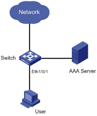
Network requirements
All departments of a company are interconnected through a switch. The 802.1x protocol is used to authenticate users and control their access to network resources. A user name is someone, and the authentication password is hello. It is connected to Ethernet 1/0/1 of the switch and belongs to the test.net domain.
It is required to configure a QoS profile to limit the rate of all the outbound IP packets of the user to 128 kbps and configuring to drop the packets exceeding the target packet rate.
Network diagram
Figure 2-1 Network diagram for QoS profile configuration
Configuration procedure
1) Configuration on the AAA server
# Configure the user authentication information and the matching relationship between the user name and the QoS profile. Refer to the user manual of the AAA server for detailed configuration.
2) Configuration on the switch
# Configure IP addresses for the RADIUS server.
<Sysname> system-view
[Sysname] radius scheme radius1
[Sysname-radius-radius1] primary authentication 10.11.1.1
[Sysname-radius-radius1] primary accounting 10.11.1.2
[Sysname-radius-radius1] secondary authentication 10.11.1.2
[Sysname-radius-radius1] secondary accounting 10.11.1.1
# Set the encryption passwords for the switch to exchange packets with the authentication RADIUS servers and accounting RADIUS servers.
[Sysname-radius-radius1] key authentication money
[Sysname-radius-radius1] key accounting money
# Configure the switch to delete the user domain name from the user name and then send the user name to the RADIUS sever.
[Sysname-radius-radius1] user-name-format without-domain
[Sysname-radius-radius1] quit
# Create the user domain test.net and specify radius1 as your RADIUS server group.
[Sysname] domain test.net
[Sysname-isp-test.net] radius-scheme radius1
[Sysname-isp-test.net] quit
# Create ACL 3000 to permit IP packets destined for any IP address.
[Sysname] acl number 3000
[Sysname-acl-adv-3000] rule 1 permit ip destination any
[Sysname-acl-adv-3000] quit
# Define a QoS profile named “example” to limit the rate of matched packets to 128 kbps and configuring to drop the packets exceeding the target packet rate.
[Sysname] qos-profile example
[Sysname-qos-profile-example] traffic-limit inbound ip-group 3000 128 exceed drop
# Enable 802.1x.
[Sysname] dot1x
[Sysname] dot1x interface Ethernet 1/0/1
After the configuration, the QoS profile named example will be applied to the user with user name someone automatically after the user passes the authentication.