- Table of Contents
-
- H3C S3600 Operation Manual-Release 1602(V1.02)
- 00-1Cover
- 00-2Product Overview
- 01-CLI Operation
- 02-Login Operation
- 03-Configuration File Management Operation
- 04-VLAN Operation
- 05-IP Address and Performance Operation
- 06-Voice VLAN Operation
- 07-GVRP Operation
- 08-Port Basic Configuration Operation
- 09-Link Aggregation Operation
- 10-Port Isolation Operation
- 11-Port Security-Port Binding Operation
- 12-DLDP Operation
- 13-MAC Address Table Management Operation
- 14-Auto Detect Operation
- 15-MSTP Operation
- 16-Routing Protocol Operation
- 17-Multicast Operation
- 18-802.1x and System Guard Operation
- 19-AAA Operation
- 20-Web Authentication Operation
- 21-MAC Address Authentication Operation
- 22-VRRP Operation
- 23-ARP Operation
- 24-DHCP Operation
- 25-ACL Operation
- 26-QoS-QoS Profile Operation
- 27-Web Cache Redirection Operation
- 28-Mirroring Operation
- 29-IRF Fabric Operation
- 30-Cluster Operation
- 31-PoE-PoE Profile Operation
- 32-UDP Helper Operation
- 33-SNMP-RMON Operation
- 34-NTP Operation
- 35-SSH Operation
- 36-File System Management Operation
- 37-FTP-SFTP-TFTP Operation
- 38-Information Center Operation
- 39-System Maintenance and Debugging Operation
- 40-VLAN-VPN Operation
- 41-HWPing Operation
- 42-IPv6 Management Operation
- 43-DNS Operation
- 44-Smart Link-Monitor Link Operation
- 45-Access Management Operation
- 46-Appendix
- Related Documents
-
| Title | Size | Download |
|---|---|---|
| 24-DHCP Operation | 709.43 KB |
Obtaining IP Addresses Dynamically
DHCP Server Configuration Task List
Configuring the Global Address Pool Based DHCP Server
Enabling the Global Address Pool Mode on Interface(s)
Creating a DHCP Global Address Pool
Configuring an Address Allocation Mode for the Global Address Pool
Configuring a Domain Name Suffix for the DHCP Client
Configuring DNS Servers for the DHCP Client
Configuring WINS Servers for the DHCP Client
Configuring Gateways for the DHCP Client
Configuring BIMS Server Information for the DHCP Client
Configuring Option 184 Parameters for the Client with Voice Service
Configuring the TFTP Server and Bootfile Name for the DHCP Client
Configuring a Self-Defined DHCP Option
Configuring the Interface Address Pool Based DHCP Server
Enabling the Interface Address Pool Mode on Interface(s)
Configuring an Address Allocation Mode for an Interface Address Pool
Configuring a Domain Name Suffix for the DHCP Client
Configuring DNS Servers for the DHCP Client
Configuring WINS Servers for the DHCP Client
Configuring BIMS Server Information for the DHCP Client
Configuring Option 184 Parameters for the Client with Voice Service
Configuring the TFTP Server and Bootfile Name for the DHCP Client
Configuring a Self-Defined DHCP Option
Configuring DHCP Server Security Functions
Enabling Unauthorized DHCP Server Detection
Configuring IP Address Detecting
Configuring DHCP Accounting Functions
Introduction to DHCP Accounting
Enabling the DHCP Server to Process Option 82
Displaying and Maintaining the DHCP Server
DHCP Server Configuration Examples
DHCP Server Configuration Example
DHCP Server with Option 184 Support Configuration Example
DHCP Accounting Configuration Example
3 DHCP Relay Agent Configuration
Introduction to DHCP Relay Agent
Option 82 Support on DHCP Relay Agent
Configuring the DHCP Relay Agent
DHCP Relay Agent Configuration Task List
Correlating a DHCP Server Group with a Relay Agent Interface
Configuring DHCP Relay Agent Security Functions
Configuring the DHCP Relay Agent to Support Option 82
Displaying and Maintaining DHCP Relay Agent Configuration
DHCP Relay Agent Configuration Example
Troubleshooting DHCP Relay Agent Configuration
Introduction to DHCP-Snooping Option 82
Configuring DHCP Snooping to Support Option 82
DHCP Snooping Configuration Examples
DHCP-Snooping Option 82 Support Configuration Example
IP Filtering Configuration Example
Displaying DHCP Snooping Configuration
5 DHCP Packet Rate Limit Configuration
Introduction to DHCP Packet Rate Limit
Configuring DHCP Packet Rate Limit
Configuring DHCP Packet Rate Limit
Configuring Port State Auto Recovery
Rate Limit Configuration Example
6 DHCP/BOOTP Client Configuration
Configuring a DHCP/BOOTP Client
DHCP Client Configuration Example
BOOTP Client Configuration Example
Displaying DHCP/BOOTP Client Configuration
1 DHCP Overview
When configuring DHCP, go to these sections for information you are interested in:
![]()
l Support for assigning a TFTP server address and bootfile name from the DHCP server to the client with auto-configuration function is added. For details, see Configuring the TFTP Server and Bootfile Name for the DHCP Client and Configuring the TFTP Server and Bootfile Name for the DHCP Client.
l Support for DHCP Snooping Option 82 is added in this manual. For details, see Introduction to DHCP-Snooping Option 82 and Configuring DHCP Snooping to Support Option 82.
l IP filtering is added in this manual. For details, see Introduction to IP Filtering and Configuring IP Filtering.
l The DHCP packet rate limit function is added in this manual. For details, refer to DHCP Packet Rate Limit Configuration.
Introduction to DHCP
With networks getting larger in size and more complicated in structure, lack of available IP addresses becomes the common situation the network administrators have to face, and network configuration becomes a tough task for the network administrators. With the emerging of wireless networks and the using of laptops, the position change of hosts and frequent change of IP addresses also require new technology. Dynamic Host Configuration Protocol (DHCP) is developed to solve these issues.
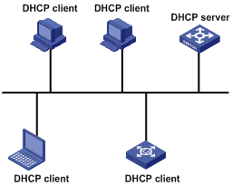
DHCP adopts a client/server model, where the DHCP clients send requests to DHCP servers for configuration parameters; and the DHCP servers return the corresponding configuration information such as IP addresses to implement dynamic allocation of network resources.
A typical DHCP application includes one DHCP server and multiple clients (such as PCs and laptops), as shown in Figure 1-1.
Figure 1-1 Typical DHCP application
DHCP IP Address Assignment
IP Address Assignment Policy
Currently, DHCP provides the following three IP address assignment policies to meet the requirements of different clients:
l Manual assignment. The administrator configures static IP-to-MAC bindings for some special clients, such as a WWW server. Then the DHCP server assigns these fixed IP addresses to the clients.
l Automatic assignment. The DHCP server assigns IP addresses to DHCP clients. The IP addresses will be occupied by the DHCP clients permanently.
l Dynamic assignment. The DHCP server assigns IP addresses to DHCP clients for predetermined period of time. In this case, a DHCP client must apply for an IP address again at the expiration of the period. This policy applies to most clients.
Obtaining IP Addresses Dynamically
A DHCP client undergoes the following four phases to dynamically obtain an IP address from a DHCP server:
1) Discover: In this phase, the DHCP client tries to find a DHCP server by broadcasting a DHCP-DISCOVER packet.
2) Offer: In this phase, the DHCP server offers an IP address. After the DHCP server receives the DHCP-DISCOVER packet from the DHCP client, it chooses an unassigned IP address from the address pool according to the priority order of IP address assignment and then sends the IP address and other configuration information together in a DHCP-OFFER packet to the DHCP client. The sending mode is decided by the flag filed in the DHCP-DISCOVER packet, refer to section DHCP Packet Format for details.
3) Select: In this phase, the DHCP client selects an IP address. If more than one DHCP server sends DHCP-OFFER packets to the DHCP client, the DHCP client only accepts the DHCP-OFFER packet that first arrives, and then broadcasts a DHCP-REQUEST packet containing the assigned IP address carried in the DHCP-OFFER packet.
![]()
l After the client receives the DHCP-ACK message, it will probe whether the IP address assigned by the server is in use by broadcasting a gratuitous ARP packet. If the client receives no response within specified time, the client can use this IP address. Otherwise, the client sends a DHCP-DECLINE message to the server and requests an IP address again.
l If there are multiple DHCP servers, IP addresses offered by other DHCP servers are assignable to other clients.
Updating IP Address Lease
After a DHCP server dynamically assigns an IP address to a DHCP client, the IP address keeps valid only within a specified lease time and will be reclaimed by the DHCP server when the lease expires. If the DHCP client wants to use the IP address for a longer time, it must update the IP lease.
By default, a DHCP client updates its IP address lease automatically by unicasting a DHCP-REQUEST packet to the DHCP server when half of the lease time elapses. The DHCP server responds with a DHCP-ACK packet to notify the DHCP client of a new IP lease if the server can assign the same IP address to the client. Otherwise, the DHCP server responds with a DHCP-NAK packet to notify the DHCP client that the IP address will be reclaimed when the lease time expires.
If the DHCP client fails to update its IP address lease when half of the lease time elapses, it will update its IP address lease by broadcasting a DHCP-REQUEST packet to the DHCP servers again when seven-eighths of the lease time elapses. The DHCP server performs the same operations as those described above.
DHCP Packet Format
DHCP has eight types of packets. They have the same format, but the values of some fields in the packets are different. The DHCP packet format is based on that of the BOOTP packets. The following figure describes the packet format (the number in the brackets indicates the field length, in bytes):
Figure 1-2 DHCP packet format
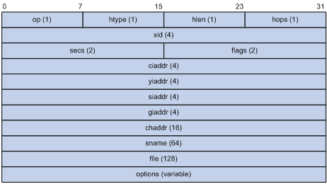
The fields are described as follows:
l op: Operation types of DHCP packets, 1 for request packets and 2 for response packets.
l htype, hlen: Hardware address type and length of the DHCP client.
l hops: Number of DHCP relay agents which a DHCP packet passes. For each DHCP relay agent that the DHCP request packet passes, the field value increases by 1.
l xid: Random number that the client selects when it initiates a request. The number is used to identify an address-requesting process.
l secs: Elapsed time after the DHCP client initiates a DHCP request.
l flags: The first bit is the broadcast response flag bit, used to identify that the DHCP response packet is a unicast (set to 0) or broadcast (set to 1). Other bits are reserved.
l ciaddr: IP address of a DHCP client.
l yiaddr: IP address that the DHCP server assigns to a client.
l siaddr: IP address of the DHCP server.
l giaddr: IP address of the first DHCP relay agent that the DHCP client passes after it sent the request packet.
l chaddr: Hardware address of the DHCP client.
l sname: Name of the DHCP server.
l file: Path and name of the boot configuration file that the DHCP server specifies for the DHCP client.
l option: Optional variable-length fields, including packet type, valid lease time, IP address of a DNS server, and IP address of the WINS server.
Protocol Specification
Protocol specifications related to DHCP include:
l RFC2131: Dynamic Host Configuration Protocol
l RFC2132: DHCP Options and BOOTP Vendor Extensions
l RFC1542: Clarifications and Extensions for the Bootstrap Protocol
l RFC3046: DHCP Relay Agent Information option
When configuring the DHCP server, go to these sections for information you are interested in:
l DHCP Server Configuration Task List
l Configuring the Global Address Pool Based DHCP Server
l Configuring the Interface Address Pool Based DHCP Server
l Configuring DHCP Server Security Functions
l Configuring DHCP Accounting Functions
l Enabling the DHCP Server to Process Option 82
l Displaying and Maintaining the DHCP Server
l DHCP Server Configuration Examples
l Troubleshooting a DHCP Server
![]()
l The contents of this chapter are only applicable to the S3600-EI series among S3600 series switches.
l Currently, the interface-related DHCP server configurations can only be made on VLAN interfaces.
Introduction to DHCP Server
Usage of DHCP Server
Generally, DHCP servers are used in the following networks to assign IP addresses:
l Large-sized networks, where manual configuration method bears heavy load and is difficult to manage the whole network in centralized way.
l Networks where the number of available IP addresses is less than that of the hosts. In this type of networks, IP addresses are not enough for all the hosts to obtain a fixed IP address, and the number of on-line users is limited (such is the case in an ISP network). In these networks, a great number of hosts must dynamically obtain IP addresses through DHCP.
l Networks where only a few hosts need fixed IP addresses and most hosts do not need fixed IP addresses.
DHCP Address Pool
A DHCP address pool holds the IP addresses to be assigned to DHCP clients. When a DHCP server receives a DHCP request from a DHCP client, it selects an address pool depending on the configuration, picks an IP address from the pool and sends the IP address and other related parameters (such as the IP address of the DNS server, and the lease time of the IP address) to the DHCP client.
Types of address pool
The address pools of a DHCP server fall into two types: global address pool and interface address pool.
l A global address pool is created by executing the dhcp server ip-pool command in system view. It is valid on the current device.
l If an interface is configured with a valid unicast IP address, you can create an interface-based address pool for the interface by executing the dhcp select interface command in interface view. The IP addresses an interface address pool holds belong to the network segment the interface resides in and are available to the interface only.
Structure of an address pool
The address pools of a DHCP server are hierarchically organized in a tree-like structure. The root holds the IP address of the natural network segment, the branches hold the subnet IP addresses, and the leaves holds the IP addresses that are manually bound to specific clients. The address pools that are of the same level are sorted by their configuration precedence order. Such a structure enables configurations to be inherited. That is, the configurations of the natural network segment can be inherited by its subnets, whose configurations in turn can be inherited by their client address. So, for the parameters that are common to the whole network segment or some subnets (such as domain name), you just need to configure them on the network segment or the corresponding subnets. The following is the details of configuration inheritance.
1) A newly created child address pool inherits the configurations of its parent address pool.
2) For an existing parent-child address pool pair, when you performs a new configuration on the parent address pool:
l The child address pool inherits the new configuration if there is no corresponding configuration on the child address pool.
l The child address pool does not inherit the new configuration if there is already a corresponding configuration on the child address pool.
![]()
The IP address lease does not enjoy the inheritance attribute.
Principles of address pool selection
The DHCP server observes the following principles to select an address pool to assign an IP address to a client:
1) If the receiving interface works in the global address pool mode, the DHCP server assigns an IP address from the global address pool to the DHCP client.
2) If the receiving interface works in the interface address pool mode, the DHCP server assigns an IP address from the interface address pool to the DHCP client directly connected to the interface. If there is no available IP address in the interface address pool, the DHCP server selects an IP address from the global address pool that contains the interface address pool’s network segment for the client.
The DHCP server assigns an IP address to the client in the following order from an interface address pool or a global address pool:
1) If there is an address pool where an IP address is statically bound to the MAC address or ID of the client, the DHCP server will select this address pool and assign the statically bound IP address to the client.
2) Otherwise, the DHCP server observes the following principles to select a dynamic address pool.
l If the client and the server reside in the same network segment, the smallest address pool that contains the IP address of the receiving interface will be selected.
l If the client and the server do not reside in the same network segment (that is, a DHCP relay agent is in-between), the smallest address pool that contains the IP address specified in the giaddr field of the client’s request will be selected.
l If no assignable IP address is available in the selected address pool, the DHCP server will not assign any IP address to the client because it cannot assign an IP address from the parent address pool to the client.
DHCP IP Address Preferences
A DHCP server assigns IP addresses in interface address pools or global address pools to DHCP clients in the following sequence:
1) IP addresses that are statically bound to the MAC addresses of DHCP clients or client IDs.
2) The IP address that was ever assigned to the client
3) The IP address designated by the Option 50 field in a DHCP-DISCOVER message
4) The first assignable IP address found in a proper DHCP address pool
5) If no IP address is available, the DHCP server queries lease-expired and conflicted IP addresses. If the DHCP server finds such IP addresses, it assigns them; otherwise the DHCP server does not assign an IP address.
IRF Support
In an IRF (intelligent resilient framework) system, DHCP servers operate in a centralized way to fit the IRF environment.
l DHCP servers run (as tasks) on all the units (including the master unit and the slave units) in a Fabric system. But only the one running on the master unit receives/sends packets and carries out all functions of a DHCP server. Those running on the slave units only operate as the backup tasks of the one running on the master unit.
l When a slave unit receives a DHCP-REQUEST packet, it redirects the packet to the DHCP server on the master unit, which returns a DHCP-ACK or DHCP-NAK packet to the DHCP client and at the same time backs up the related information to the slave units. In this way, when the current master unit fails, one of the slaves can change to the master and operates as the DHCP server immediately.
l DHCP is an UDP-based protocol operating at the application layer. When a DHCP server in a fabric system runs on a Layer 2 network device, DHCP packets are directly forwarded by hardware instead of being delivered to the DHCP server, or being redirected to the master unit by UDP HELPER. This idles the DHCP server. DHCP packets can be redirected to the DHCP server on the master unit by UDP HELPER only when the Layer 2 device is upgraded to a Layer 3 device.
![]()
l When you merge two or more IRF systems into one IRF system, a new master unit is elected, and the new IRF system adopts new configurations accordingly. This may result in the existing system configurations (including the address pools configured for the DHCP servers) being lost. As the new IRF system cannot inherit the original DHCP server configurations, you need to perform DHCP server configurations for it.
l When an IRF system is split into multiple new IRF systems, some of the new IRF systems may be degraded to Layer 2 devices. For a new IRF system degraded to Layer 2 device, although the original DHCP server still exists in the new system, it runs idle for being unable to receive any packets. When the IRF system restores to a Layer 3 device due to being merged into a new IRF system, it adopts the configurations on the new IRF system. And you need to perform DHCP server configurations if the new IRF system does not have DHCP server-related configurations.
l In an IRF system, the UDP HELPER function must be enabled on the DHCP servers that are in fabric state.
DHCP Server Configuration Task List
Complete the following tasks to configure the DHCP server:
|
Task |
Remarks |
|
|
Required |
||
|
Configure address pool based DHCP server |
One of the two options is required |
|
|
Optional |
||
|
Optional |
||
|
Optional |
||
Enabling DHCP
You need to enable DHCP to make other related configurations take effect.
Follow these steps to enable DHCP:
|
To do… |
Use the command… |
Remarks |
|
Enter system view |
system-view |
— |
|
Enable DHCP |
dhcp enable |
Optional By default, DHCP is enabled. |
![]()
To improve security and avoid malicious attacks to unused sockets, S3600 Ethernet switches provide the following functions:
l UDP port 67 and UDP port 68 ports used by DHCP are enabled only when DHCP is enabled.
l UDP port 67 and UDP port 68 ports are disabled when DHCP is disabled.
The corresponding implementation is as follows:
l After DHCP is enabled with the dhcp enable command, if the DHCP server and DHCP relay agent functions are not configured, UDP port 67 and UDP port 68 ports are kept disabled; if the DHCP server or DHCP relay agent function is configured, UDP port 67 and UDP port 68 ports are enabled.
l After DHCP is disabled with the undo dhcp enable command, even if the DHCP server or DHCP relay function is configured, UDP port 67 and UDP port 68 ports will be disabled.
Configuring the Global Address Pool Based DHCP Server
Configuration Task List
Complete the following tasks to configure the global address pool based DHCP server:
|
Task |
Remarks |
|
|
Required |
||
|
Required |
||
|
Configuring an Address Allocation Mode for the Global Address Pool |
One of the two options is required Only one mode can be selected for the same global address pool. |
|
|
Optional |
||
|
Optional |
||
|
Optional |
||
|
Optional |
||
|
Optional |
||
|
Configuring Option 184 Parameters for the Client with Voice Service |
Optional |
|
|
Configuring the TFTP Server and Bootfile Name for the DHCP Client |
Optional |
|
|
Optional |
||
Enabling the Global Address Pool Mode on Interface(s)
Follow these steps to configure the global address pool mode on interface(s):
|
To do… |
Use the command… |
Remarks |
|
|
Enter system view |
system-view |
— |
|
|
Configure the specified interface(s) or all the interfaces to operate in global address pool mode |
Configure the current interface |
interface interface-type interface-number |
Optional By default, the interface operates in global address pool mode. |
|
dhcp select global |
|||
|
quit |
|||
|
Configure multiple interfaces simultaneously in system view |
dhcp select global { interface interface-type interface-number [ to interface-type interface-number ] | all } |
||
Creating a DHCP Global Address Pool
Follow these steps to create a DHCP address pool:
|
To do… |
Use the command… |
Remarks |
|
Enter system view |
system-view |
— |
|
Create a DHCP global address pool and enter its view |
dhcp server ip-pool pool-name |
Required Not created by default. |
Configuring an Address Allocation Mode for the Global Address Pool
![]()
You can configure either the static IP address allocation mode or the dynamic IP address allocation mode for a global address pool, and only one mode can be configured for one DHCP global address pool.
For dynamic IP address allocation, you need to specify the range of the IP addresses to be dynamically assigned. But for static IP address binding, you can regard that the IP address statically bound to a DHCP client comes from a special DHCP address pool that contains only one IP address.
Configuring the static IP address allocation mode
Some DHCP clients, such as WWW servers, need fixed IP addresses. This can be achieved by binding IP addresses to the MAC addresses of these DHCP clients. When such a DHCP client requests an IP address, the DHCP server searches for the IP address corresponding to the MAC address of the DHCP client and assigns the IP address to the DHCP client.
When some DHCP clients send DHCP-DISCOVER packets to the DHCP server to apply for IP addresses, they construct client IDs and add them in the DHCP-DISCOVER packets. If the bindings of client IDs and IP addresses are configured on the DHCP server, when such a client requests an IP address, the DHCP server will find the corresponding IP address based on the client ID and assign it to the DHCP client.
Currently, only one IP address in a global DHCP address pool can be statically bound to a MAC address or a client ID.
Follow these steps to configure the static IP address allocation mode:
|
To do… |
Use the command… |
Remarks |
|
|
Enter system view |
system-view |
— |
|
|
Enter DHCP address pool view |
dhcp server ip-pool pool-name |
— |
|
|
Configure an IP address to be statically bound |
static-bind ip-address ip-address [ mask mask ] |
Required By default, no IP address is statically bound. |
|
|
Bind an IP address to the MAC address of a DHCP client or a client ID statically |
Configure the MAC address to which the IP address is to be statically bound |
static-bind mac-address mac-address |
One of these two options is required By default, no MAC address or client ID to which an IP address is to be statically bound is configured. |
|
Configure the client ID to which the IP address is to be statically bound |
static-bind client-identifier client-identifier |
||
![]()
l The static-bind ip-address command and the static-bind mac-address command or the static-bind client-identifier command must be coupled.
l In the same global DHCP address pool, if you configure the static-bind client-identifier command after configuring the static-bind mac-address command, the new configuration overwrites the previous one, and vice versa.
l In the same global DHCP address pool, if the static-bind ip-address command, the static-bind mac-address command, or the static-bind client-identifier is executed repeatedly, the new configuration overwrites the previous one.
l The IP address to be statically bound cannot be an interface IP address of the DHCP server; otherwise static binding does not take effect.
l A client can permanently use the statically-bound IP address that it has obtained. The IP address is not limited by the lease time of the IP addresses in the address pool.
![]()
To improve security and avoid malicious attack to the unused sockets, S3600 Ethernet switches provide the following functions:
l UDP 67 and UDP 68 ports used by DHCP are enabled only when DHCP is enabled.
l UDP 67 and UDP 68 ports are disabled when DHCP is disabled.
The corresponding implementation is as follows:
l After a DHCP address pool is created by executing the dhcp server ip-pool command, the UDP 67 and UDP 68 ports used by DHCP are enabled.
l After a DHCP address pool is deleted by executing the undo dhcp server ip-pool command and all other DHCP functions are disabled, UDP 67 and UDP 68 ports used by DHCP are disabled accordingly.
Configuring the dynamic IP address allocation mode
IP addresses dynamically assigned to DHCP clients (including those that are permanently leased and those that are temporarily leased) belong to addresses segments that are previously specified. Currently, an address pool can contain only one address segment, whose ranges are determined by the subnet mask.
To avoid address conflicts, the DHCP server automatically excludes IP addresses (used by the gateway, FTP server and so forth) specified with the dhcp server forbidden-ip command from dynamic allocation.
The lease time can differ with address pools. But that of the IP addresses of the same address pool are the same. Lease time is not inherited, that is to say, the lease time of a child address pool is not affected by the configuration of the parent address pool.
Follow these steps to configure the dynamic IP address allocation mode:
|
To do… |
Use the command… |
Remarks |
|
Enter system view |
system-view |
— |
|
Enter DHCP address pool view |
dhcp server ip-pool pool-name |
— |
|
Set the IP address segment whose IP address are to be assigned dynamically |
network network-address [ mask mask ] |
Required By default, no IP address segment is set. That is, no IP address is available for being assigned |
|
Configure the lease time |
expired { day day [ hour hour [ minute minute ] ] | unlimited } |
Optional The default lease time is one day |
|
Return to system view |
quit |
— |
|
Specify the IP addresses that are not dynamically assigned |
dhcp server forbidden-ip low-ip-address [ high-ip-address ] |
Optional By default, except the IP addresses of DHCP server interfaces, all IP addresses in a DHCP address pool are assignable. |
![]()
l In the same DHCP global address pool, the network command can be executed repeatedly. In this case, the new configuration overwrites the previous one.
l The dhcp server forbidden-ip command can be executed repeatedly. That is, you can configure multiple IP addresses that are not dynamically assigned to DHCP clients.
l If an IP address that is not to be automatically assigned has been configured as a statically-bound IP address, the DHCP server still assigns this IP address to the client whose MAC address or ID has been bound.
Configuring a Domain Name Suffix for the DHCP Client
You can configure a domain name suffix in each DHCP address pool on the DHCP server. The DHCP server will provide the domain name suffix together with an IP address to the DHCP client.
With this suffix assigned, the client needs only input part of the domain name, and the system will add the domain name suffix for name resolution. For details about DNS, refer to DNS Operation in this manual.
Follow these steps to configure a domain name suffix for the DHCP client:
|
To do… |
Use the command… |
Remarks |
|
Enter system view |
system-view |
— |
|
Enter DHCP address pool view |
dhcp server ip-pool pool-name |
— |
|
Configure a domain name suffix for the client |
domain-name domain-name |
Required Not configured by default. |
Configuring DNS Servers for the DHCP Client
If a client accesses a host on the Internet through domain name, DNS (domain name system) is needed to translate the domain name into the corresponding IP address. To enable DHCP clients to access hosts on the Internet through domain names, a DHCP server is required to provide DNS server addresses while assigning IP addresses to DHCP clients. Currently, you can configure up to eight DNS server addresses for a DHCP address pool.
Follow these steps to configure DNS servers for the DHCP client:
|
To do… |
Use the command… |
Remarks |
|
Enter system view |
system-view |
— |
|
Enter DHCP address pool view |
dhcp server ip-pool pool-name |
— |
|
Configure DNS server addresses for DHCP clients |
dns-list ip-address&<1-8> |
Required By default, no DNS server address is configured. |
Configuring WINS Servers for the DHCP Client
For Microsoft Windows-based DHCP clients that communicate through NetBIOS protocol, the host name-to-IP address translation is carried out by Windows internet naming service (WINS) servers. So you need to perform WINS-related configuration for most Windows-based hosts.
To implement host name-to-IP address translation for DHCP clients, you should enable the DHCP server to assign WINS server addresses when assigning IP addresses to DHCP clients. Currently, you can configure up to eight WINS addresses for a DHCP address pool.
Host name-to-IP address mappings are needed for DHCP clients communicating through NetBIOS protocol. According to the way to establish the mapping, NetBIOS nodes fall into the following four categories:
l B-node. Nodes of this type establish their mappings through broadcasting (The character b stands for the word broadcast). The source node obtains the IP address of the destination node by sending the broadcast packet containing the host name of the destination node. After receiving the broadcast packet, the destination node returns its IP address to the source node.
l P-node. Nodes of this type establish their mappings by sending unicast packets to WINS servers. (The character p stands for peer-to-peer). The source node sends the unicast packet to the WINS server. After receiving the unicast packet, the WINS server returns the IP address corresponding to the destination node name to the source node.
l M-node. Nodes of this type are p-nodes mixed with broadcasting features (The character m stands for the word mixed), that is to say, this type of nodes obtain mappings by sending broadcast packets first. If they fail to obtain mappings, they send unicast packets to the WINS server to obtain mappings.
l H-node. Nodes of this type are b-nodes mixed with peer-to-peer features. (The character h stands for the word hybrid), that is to say, this type of nodes obtain mappings by sending unicast packets to WINS servers first. If they fail to obtain mappings, they send broadcast packets to obtain mappings.
Follow these steps to configure WINS servers for the DHCP client:
|
To do… |
Use the command… |
Remarks |
|
Enter system view |
system-view |
— |
|
Enter DHCP address pool view |
dhcp server ip-pool pool-name |
— |
|
Configure WINS server addresses for DHCP clients |
nbns-list ip-address&<1-8> |
Required By default, no WINS server address is configured. |
|
Configure DHCP clients to be of a specific NetBIOS node type |
netbios-type { b-node | h-node | m-node | p-node } |
Optional By default, no NetBIOS node type of the DHCP client is specified. |
![]()
If b-node is specified for the client, you don’t need to specify any WINS server address.
Configuring Gateways for the DHCP Client
Gateways are necessary for DHCP clients to access servers/hosts outside the current network segment. After you configure gateway addresses on a DHCP server, the DHCP server provides the gateway addresses to DHCP clients as well while assigning IP addresses to them.
You can configure gateway addresses for global address pools on a DHCP server. Currently, you can configure up to eight gateway addresses for a DHCP address pool.
Follow these steps to configure gateways for the DHCP client:
|
To do… |
Use the command… |
Remarks |
|
Enter system view |
system-view |
— |
|
Enter DHCP address pool view |
dhcp server ip-pool pool-name |
— |
|
Configure gateway addresses for DHCP clients |
gateway-list ip-address&<1-8> |
Required By default, no gateway address is configured. |
Configuring BIMS Server Information for the DHCP Client
A DHCP client performs regular software update and backup using configuration files obtained from a branch intelligent management system (BIMS) server. Therefore, the DHCP server needs to offer DHCP clients the BIMS server IP address, port number, shared key from the DHCP address pool.
Follow these steps to configure BIMS server information for the DHCP client:
|
To do… |
Use the command… |
Remarks |
|
Enter system view |
system-view |
— |
|
Enter DHCP address pool view |
dhcp server ip-pool pool-name |
— |
|
Configure the BIMS server information to be assigned to the DHCP client |
bims-server ip ip-address [ port port-number ] sharekey key |
Required By default, no BIMS server information is configured. |
Configuring Option 184 Parameters for the Client with Voice Service
Option 184 is a reserved option, and the information it carries can be customized. You can define four sub-options for this option after enabling the DHCP server. Thus, besides obtaining an IP address, the DHCP client with voice services can obtain voice related parameters from the DHCP address pool.
Basic concept
The four sub-options of Option 184 mainly carry information about voice. The following lists the sub-options and the carried information:
l Sub-option 1: IP address of the network call processor (NCP-IP).
l Sub-option 2: IP address of the alternate server (AS-IP).
l Sub-option 3: Voice VLAN configuration.
l Sub-option 4: Fail-over call routing.
Meanings of the sub-options for Option 184
Table 2-1 Meanings of the sub-options for Option 184
|
Sub-option |
Feature |
Function |
Note |
|
NCP-IP (sub-option 1) |
The NCP-IP sub-option carries the IP address of the network call processor (NCP). |
The IP address of the NCP server carried by sub-option 1 of Option 184 is intended for identifying the server serving as the network call controller and the server used for application downloading. |
When used in Option 184, this sub-option must be the first sub-option, that is, sub-option 1 |
|
AS-IP (sub-option 2) |
The AS-IP sub-option carries the IP address of the alternate server (AS). |
The alternate NCP server identified by sub-option 2 of Option 184 acts as the backup of the NCP server. The NCP server specified by this option is used only when the IP address carried by the NCP-IP sub-option is unreachable or invalid. |
The AS-IP sub-option takes effect only when sub-option 1 (that is, the NCP-IP sub-option) is defined |
|
Voice VLAN Configuration (sub-option 3) |
The voice VLAN configuration sub-option carries the ID of the voice VLAN and the flag indicating whether the voice VLAN identification function is enabled. |
The sub-option 3 of Option 184 comprises two parts: l One part carries the flag indicating whether the voice VLAN identification function is enabled. l The other part carries the ID of the voice VLAN. |
l A flag value of 0 indicates that the voice VLAN identification function is not enabled, in which case the information carried by the VLAN ID part will be neglected. l A flag value of 1 indicates that the voice VLAN identification function is enabled. |
|
Fail-Over Call Routing (sub-option 4) |
The fail-over call routing sub-option carries the IP address for fail-over call routing and the associated dial number. The IP address for fail-over call routing and the dial number in sub-option 4 of Option 184 refer to the IP address and dial number of the Session Initiation Protocol (SIP) peer. |
When the NCP server is unreachable, a SIP user can use the configured IP address and dial number of the peer to establish a connection and communicate with the peer SIP user. |
— |
![]()
For the configurations specifying to add sub-option 2, sub-option 3, and sub-option 4 in the response packets to take effect, you need to configure the DHCP server to add sub-option 1.
Mechanism of using Option 184 on DHCP server
The DHCP server encapsulates the information for Option 184 to carry in the response packets sent to the DHCP clients. Supposing that the DHCP clients are on the same segment as the DHCP server, the mechanism of Option 184 on the DHCP server is as follows:
1) A DHCP client sends to the DHCP server a request packet carrying Option 55, which indicates the client requests the configuration parameters of Option 184.
2) The DHCP server checks the request list in Option 55 carried by the request packet, and then adds the sub-options of Option 184 in the Options field of the response packet to be sent to the DHCP client.
![]()
Only when the DHCP client specifies in Option 55 of the request packet that it requires Option 184, does the DHCP server add Option 184 in the response packet sent to the client.
Configuring Option 184 Parameters for the DHCP Client with Voice Service
Follow these steps to configure Option 184 parameters for the DHCP client with voice service:
|
To do… |
Use the command… |
Remarks |
|
Enter system view |
system-view |
— |
|
Enter DHCP address pool view |
dhcp server ip-pool pool-name |
— |
|
Specify the IP address of the primary network calling processor |
voice-config ncp-ip ip-address |
Required Not specified by default. |
|
Specify the IP address of the backup network calling processor |
voice-config as-ip ip-address |
Optional Not specified by default. |
|
Configure the voice VLAN |
voice-config voice-vlan vlan-id { disable | enable } |
Optional Not configured by default. |
|
Specify the failover IP address |
voice-config fail-over ip-address dialer-string |
Optional No failover IP address is specified by default. |
![]()
Specify an IP address for the network calling processor before performing other configuration.
Configuring the TFTP Server and Bootfile Name for the DHCP Client
This task is to specify the IP address and name of a TFTP server and the bootfile name in the DHCP global address pool. The DHCP clients use these parameters to contact the TFTP server, requesting the configuration file used for system initialization, which is called auto-configuration. The request process of the client is described below:
1) When a switch starts up without loading any configuration file, the system sets the specified interface (VLAN-interface 1) as the DHCP client to request from the DHCP server parameters such as the IP address and name of a TFTP server, and bootfile name.
2) After getting related parameters, the DHCP client will send a TFTP request to obtain the configuration file from the specified TFTP server for system initialization. If the client cannot get related parameters, it will perform system initialization without loading any configuration file.
To implement auto-configuration, you need to specify the IP address and name of a TFTP server and the bootfile name on the DHCP server, but you do not need to perform any configuration on the DHCP client.
When Option 55 in a client’s request contains parameters of Option 66, Option 67, or Option 150, the DHCP server will return the IP address and name of the specified TFTP server, bootfile name and an IP address to the client, which uses such information to complete auto-configuration.
Follow these steps to configure the TFTP server and bootfile name for the DHCP client:
|
Use the command… |
Remarks |
|
|
Enter system view |
system-view |
— |
|
Enter DHCP address pool view |
dhcp server ip-pool pool-name |
— |
|
Specify the TFTP server |
tftp-server ip-address ip-address |
Optional Not specified by default. |
|
Specify the name of the TFTP server |
tftp-server domain-name domain-name |
Optional Not specified by default. |
|
Specify the bootfile name |
bootfile-name bootfile-name |
Optional Not specified by default. |
Configuring a Self-Defined DHCP Option
By configuring self-defined DHCP options, you can:
l Define new DHCP options. New configuration options will come out with DHCP development. To support new options, you can add them into the attribute list of the DHCP server.
l Extend existing DHCP options. When the current DHCP options cannot meet customers’ requirements (for example, you cannot use the dns-list command to configure more than eight DNS server addresses), you can configure a self defined option for extension.
Follow these steps to configure a self-defined DHCP option:
|
To do… |
Use the command… |
Remarks |
|
Enter system view |
system-view |
— |
|
Enter DHCP address pool view |
dhcp server ip-pool pool-name |
— |
|
Configure a self-defined DHCP option |
option code { ascii ascii-string | hex hex-string&<1-10> | ip-address ip-address&<1-8> } |
Required Not configured by default. |
![]()
Be cautious when configuring self-defined DHCP options because such configuration may affect the DHCP operation process.
Configuring the Interface Address Pool Based DHCP Server
![]()
In the interface address pool mode, after the addresses in the interface address pool have been assigned, the DHCP server picks IP addresses from the global interface address pool containing the network segment of the interface address pool and assigns them to the DHCP clients. As a result, the IP addresses obtained from global address pools and those obtained from interface address pools are not on the same network segment, so the clients cannot communicate with each other.
Therefore, in the interface address pool mode, if the DHCP clients in a VLAN need to obtain IP addresses from the same network segment, the number of DHCP clients cannot exceed the number of the IP addresses assignable in the VLAN interface address pool.
Configuration Task List
An interface address pool is created when the interface is assigned a valid unicast IP address and you execute the dhcp select interface command in interface view. The IP addresses contained in it belong to the network segment where the interface resides in and are available to the interface only.
You can perform certain configurations for DHCP address pools of an interface or multiple interfaces within specified interface ranges. Configuring for multiple interfaces eases configuration work load and makes you to configure in a more convenient way.
Complete the following tasks to configure the interface address pool based DHCP server:
|
Task |
Remarks |
|
|
Required |
||
|
Configuring an Address Allocation Mode for an Interface Address Pool |
One of the two options is required. And these two options can be configured at the same time. |
|
|
Optional |
||
|
Optional |
||
|
Optional |
||
|
Optional |
||
|
Configuring Option 184 Parameters for the Client with Voice Service |
Optional |
|
|
Configuring the TFTP Server and Bootfile Name for the DHCP Client |
Optional |
|
|
Optional |
||
![]()
When an S3600-EI Ethernet switch works in the interface address pool mode as a DHCP server, the only gateway address it can assign to a client is the primary IP address of the interface.
Enabling the Interface Address Pool Mode on Interface(s)
If the DHCP server works in the interface address pool mode, it picks IP addresses from the interface address pools and assigns them to the DHCP clients. If there is no available IP address in the interface address pools, the DHCP server picks IP addresses from its global address pool that contains the interface address pool segment and assigns them to the DHCP clients.
Follow these steps to configure interface address pool mode on interface(s):
|
To do… |
Use the command… |
Remarks |
|
|
Enter system view |
system-view |
— |
|
|
Configure interface address pool mode |
On the current interface |
interface interface-type interface-number |
Required By default, a DHCP server assigns the IP addresses of the global address pool to DHCP clients. |
|
dhcp select interface |
|||
|
quit |
|||
|
On multiple interfaces in system view |
dhcp select interface { interface interface-type interface-number [ to interface-type interface-number ] | all } |
||
You need to configure an IP address for the interface before enabling the interface address pool mode on it.
![]()
To improve security and avoid malicious attack to the unused sockets, S3600 Ethernet switches provide the following functions:
l UDP port 67 and UDP port 68 ports used by DHCP are enabled only when DHCP is enabled.
l UDP port 67 and UDP port 68 ports are disabled when DHCP is disabled.
The corresponding implementation is as follows:
l After a DHCP interface address pool is created by executing the dhcp select interface command, UDP port 67 and UDP port 68 ports used by DHCP are enabled.
l After a DHCP interface address pool is deleted by executing the undo dhcp select interface command and all other DHCP functions are disabled, UDP port 67 and UDP port 68 ports used by DHCP are disabled accordingly.
Configuring an Address Allocation Mode for an Interface Address Pool
Configuring the static IP address allocation mode
Some DHCP clients, such as WWW servers, need fixed IP addresses. This is achieved by binding IP addresses to the MAC addresses of these DHCP clients. When such a DHCP client applies for an IP address, the DHCP server finds the IP address corresponding to the MAC address of the DHCP client, and then assigns the IP address to the DHCP client.
When some DHCP clients send DHCP-DISCOVER packets to the DHCP server to apply for IP addresses, they construct client IDs and add them in the DHCP-DISCOVER packets. The DHCP server finds the corresponding IP addresses based on the client IDs and assigns them to the DHCP clients.
Follow these steps to configure the static IP address allocation mode:
|
To do… |
Use the command… |
Remarks |
|
Enter system view |
system-view |
— |
|
Enter interface view |
interface interface-type interface-number |
— |
|
Configure static binding |
dhcp server static-bind ip-address ip-address { client-identifier client-identifier | mac-address mac-address } |
Required By default, static binding is not configured. |
![]()
l The IP addresses statically bound in interface address pools and the interface IP addresses must be in the same network segment.
l There is no limit to the number of IP addresses statically bound in an interface address pool, but the IP addresses statically bound in interface address pools and the interface IP addresses must be in the same segment.
l An IP address can be statically bound to only one MAC address or one client ID. A MAC address or client ID can be bound with only one IP address statically.
Configuring the dynamic IP address allocation mode
As an interface-based address pool is created after the interface is assigned a valid unicast IP address, the IP addresses contained in the address pool belong to the network segment where the interface resides in and are available to the interface only. So specifying the range of the IP addresses to be dynamically assigned is unnecessary.
To avoid address conflicts, the DHCP server automatically excludes IP addresses (used by the gateway, FTP server and so forth) specified with the dhcp server forbidden-ip command from dynamic allocation.
To avoid IP address conflicts, the IP addresses to be dynamically assigned to DHCP clients are those not occupied by specific network devices (such as gateways and FTP servers).
The lease time can differ with address pools. But that of the IP addresses of the same address pool are the same. Lease time is not inherited, that is to say, the lease time of a child address pool is not affected by the configuration of the parent address pool.
Follow these steps to configure the dynamic IP address allocation mode:
|
To do… |
Use the command… |
Remarks |
|
|
Enter system view |
system-view |
— |
|
|
Configure the lease time |
Configure for the current interface |
interface interface-type interface-number |
Optional The default lease time is one day. |
|
dhcp server expired { day day [ hour hour [ minute minute ] ] | unlimited } |
|||
|
quit |
|||
|
Configure multiple interfaces in system view |
dhcp server expired { day day [ hour hour [ minute minute ] ] | unlimited } { interface interface-type interface-number [ to interface-type interface-number ] | all } |
||
|
Specify the IP addresses that are not dynamically assigned |
dhcp server forbidden-ip low-ip-address [ high-ip-address ] |
Optional By default, all IP addresses in a DHCP address pool are available for being dynamically assigned. |
|
![]()
l The dhcp server forbidden-ip command can be executed repeatedly. That is, you can configure multiple IP addresses that are not dynamically assigned to DHCP clients.
l Use the dhcp server forbidden-ip command to configure the IP addresses that are not assigned dynamically in global address pools and interface address pools.
l If an IP address that is not to be automatically assigned has been configured as a statically-bound IP address, the DHCP server still assigns this IP address to the client whose MAC address or client ID has been bound.
Configuring a Domain Name Suffix for the DHCP Client
You can configure a suffix for the domain name in each DHCP interface address pool on the DHCP server. The DHCP server provides the domain name suffix together with an IP address for a requesting DHCP client.
Follow these steps to configure a domain name suffix for the client:
|
To do… |
Use the command… |
Remarks |
|
|
Enter system view |
system-view |
— |
|
|
Configure a domain name suffix for the clients |
In the current interface address pool |
interface interface-type interface-number |
Required Not configured by default. |
|
dhcp server domain-name domain-name |
|||
|
quit |
|||
|
In multiple interface address pools in system view |
dhcp server domain-name domain-name { all | interface interface-type interface-number [ to interface-type interface-number ] } |
||
Configuring DNS Servers for the DHCP Client
If a client accesses a host on the Internet through domain name, DNS is needed to translate the domain name into the corresponding IP address. To enable DHCP clients to access hosts on the Internet through domain names, a DHCP server is required to provide DNS server addresses while assigning IP addresses to DHCP clients. Currently, you can configure up to eight DNS server addresses for a DHCP interface address pool.
Follow these steps to configure DNS servers for the DHCP client:
|
To do… |
Use the command… |
Remarks |
|
|
Enter system view |
system-view |
— |
|
|
Configure DNS server addresses for DHCP clients |
Configure the current interface |
interface interface-type interface-number |
Required By default, no DNS server address is configured. |
|
dhcp server dns-list ip-address&<1-8> |
|||
|
quit |
|||
|
Configure multiple interfaces in system view |
dhcp server dns-list ip-address&<1-8> { interface interface-type interface-number [ to interface-type interface-number ] | all } |
||
Configuring WINS Servers for the DHCP Client
For Microsoft Windows-based DHCP clients that communicate through NetBIOS protocol, the host name-to-IP address translation is carried out by WINS servers. So you need to perform WINS-related configuration for most Windows-based hosts.
To implement host name-to-IP address translation for DHCP clients, you should enable the DHCP server to assign WINS server addresses when assigning IP addresses to DHCP clients. Currently, you can configure up to eight WINS addresses for a DHCP address pool.
Host name-to-IP address mappings are needed for DHCP clients communicating through the NetBIOS protocol. According to the way to establish the mapping, NetBIOS nodes fall into the following four categories:
l B-node. Nodes of this type establish their mappings through broadcasting (The character b stands for the word broadcast). The source node obtains the IP address of the destination node by sending the broadcast packet containing the host name of the destination node. After receiving the broadcast packet, the destination node returns its IP address to the source node.
l P-node. Nodes of this type establish their mappings by communicating with WINS servers (The character p stands for peer-to-peer). The source node sends the unicast packet to the WINS server. After receiving the unicast packet, the WINS server returns the IP address corresponding to the destination node name to the source node.
l M-node. Nodes of this type are p-nodes mixed with broadcasting features (The character m stands for the word mixed), that is to say, this type of nodes obtain mappings by sending broadcast packets first. If they fail to obtain mappings, they send unicast packets to the WINS server to obtain mappings.
l H-node. Nodes of this type are b-nodes mixed with peer-to-peer features (The character h stands for the word hybrid), that is to say, this type of nodes obtain mappings by sending unicast packets to WINS servers first. If they fail to obtain mappings, they send broadcast packets to obtain mappings.
Follow these steps to configure WINS servers for the DHCP client:
|
To do… |
Use the command… |
Remarks |
|
|
Enter system view |
system-view |
— |
|
|
Configure WINS server addresses for DHCP clients |
Configure the current interface |
interface interface-type interface-number |
Required By default, no WINS server address is configured. |
|
dhcp server nbns-list ip-address&<1-8> |
|||
|
quit |
|||
|
Configure multiple interfaces in system view |
dhcp server nbns-list ip-address&<1-8> { interface interface-type interface-number [ to interface-type interface-number ] | all } |
||
|
Configure a NetBIOS node type for DHCP clients |
Configure the current interface |
interface interface-type interface-number |
Required By default, no NetBIOS node type is specified. |
|
dhcp server netbios-type { b-node | h-node | m-node | p-node } |
|||
|
quit |
|||
|
Configure multiple interfaces in system view |
dhcp server netbios-type { b-node | h-node | m-node | p-node } { interface interface-type interface-number [ to interface-type interface-number ] | all } |
||
![]()
If b-node is specified for the client, you don’t need to specify any WINS server address.
Configuring BIMS Server Information for the DHCP Client
A DHCP client performs regular software update and backup using configuration files obtained from a BIMS server. Therefore, the DHCP server needs to offer DHCP clients the BIMS server IP address, port number, shared key from the DHCP address pool.
Follow these steps to configure BIMS server information for the DHCP client:
|
To do… |
Use the command… |
Remarks |
|
Enter system view |
system-view |
— |
|
Configure the BIMS server information to be assigned to the DHCP client |
dhcp server bims-server ip ip-address [ port port-number ] sharekey key { interface interface-type interface-number [ to interface-type interface-number ] | all } |
Required By default, no BIMS server information is configured. |
Configuring Option 184 Parameters for the Client with Voice Service
For details about Option 184, refer to Configuring Option 184 Parameters for the Client with Voice Service.
Follow these steps to configure Option 184 parameters for the client with voice service:
|
To do… |
Use the command… |
Remarks |
|
|
Enter system view |
system-view |
— |
|
|
Configure Option 184 in the current interface address pool |
Enter interface view |
interface interface-type interface-number |
— |
|
Specify the primary network calling processor |
dhcp server voice-config ncp-ip ip-address |
Required Not specified by default. |
|
|
Specify the backup network calling processor |
dhcp server voice-config as-ip ip-address |
Optional Not specified by default. |
|
|
Configure the voice VLAN |
dhcp server voice-config voice-vlan vlan-id { disable | enable } |
Optional Not configured by default. |
|
|
Specify the failover IP address |
dhcp server voice-config fail-over ip-address dialer-string |
Optional Not specified by default. |
|
|
Return to system view |
quit |
— |
|
|
Configure Option 184 in multiple interface address pools |
Specify the primary network calling processor |
dhcp server voice-config ncp-ip ip-address { all | interface interface-type interface-number [ to interface-type interface-number ] } |
Required Not specified by default. |
|
Specify the backup network calling processor |
dhcp server voice-config as-ip ip-address { all | interface interface-type interface-number [ to interface-type interface-number ] } |
Optional Not specified by default. |
|
|
Configure the voice VLAN |
dhcp server voice-config voice-vlan vlan-id { disable | enable } { all | interface interface-type interface-number [ to interface-type interface-number ] } |
Optional Not specified by default. |
|
|
Specify the failover IP address |
dhcp server voice-config fail-over ip-address dialer-string { all | interface interface-type interface-number [ to interface-type interface-number ] } |
Optional Not specified by default. |
|
![]()
Specify an IP address for the network calling processor before performing other configuration.
Configuring the TFTP Server and Bootfile Name for the DHCP Client
For related principles, refer to Configuring the TFTP Server and Bootfile Name for the DHCP Client.
Follow these steps to configure the TFTP server and bootfile name for the DHCP client:
|
To do… |
Use the command… |
Remarks |
|
|
Enter system view |
system-view |
— |
|
|
Specify the IP address and name of the TFTP server and the bootfile name in the current interface address pool |
Enter interface view |
interface interface-type interface-number |
— |
|
Specify the TFTP server |
dhcp server tftp-server ip-address ip-address |
Optional Not specified by default. |
|
|
Specify the TFTP server name |
dhcp server tftp-server domain-name domain-name |
||
|
Specify the bootfile name |
dhcp server bootfile-name bootfile-name |
||
|
Return to system view |
quit |
— |
|
|
Specify the IP address and name of the TFTP server and the bootfile name in the specified interface address pool |
Specify the TFTP server |
dhcp server tftp-server ip-address ip-address { all | interface interface-type interface-number } |
Optional Not specified by default. |
|
Specify the TFTP server name |
dhcp server tftp-server domain-name domain-name { all | interface interface-type interface-number } |
||
|
Specify the bootfile name |
dhcp server bootfile-name bootfile-name { all | interface interface-type interface-number } |
||
Configuring a Self-Defined DHCP Option
By configuring self-defined DHCP options, you can:
l Define new DHCP options. New configuration options will come out with DHCP development. To support new options, you can add them into the attribute list of the DHCP server.
l Extend existing DHCP options. When the current DHCP options cannot meet customers’ requirements (for example, you cannot use the dns-list command to configure more than eight DNS server addresses), you can configure a self defined option for extension.
Follow these steps to customize the DHCP service:
|
To do… |
Use the command… |
Remarks |
|
|
Enter system view |
system-view |
— |
|
|
Configure customized options |
Configure the current interface |
interface interface-type interface-number |
Required By default, no customized option is configured. |
|
dhcp server option code { ascii ascii-string | hex hex-string&<1-10> | ip-address ip-address&<1-8> } |
|||
|
quit |
|||
|
Configure multiple interfaces in system view |
dhcp server option code { ascii ascii-string | hex hex-string&<1-10> | ip-address ip-address&<1-8> } { interface interface-type interface-number [ to interface-type interface-number ] | all } |
||
![]()
Be cautious when configuring self-defined DHCP options because such configuration may affect the DHCP operation process.
Configuring DHCP Server Security Functions
DHCP security configuration is needed to ensure the security of DHCP service.
Prerequisites
Before configuring DHCP security, you should first complete the DHCP server configuration (either global address pool-based or interface address pool-based DHCP server configuration).
Enabling Unauthorized DHCP Server Detection
If there is an unauthorized DHCP server in the network, when a client applies for an IP address, the unauthorized DHCP server may assign an incorrect IP address to the client.
With this feature enabled, when receiving a DHCP message with the siaddr field not being 0 from a client, the DHCP server will record the value of the siaddr field and the receiving interface. The administrator can use such information to check out any DHCP unauthorized servers.
Follow these steps to enable unauthorized DHCP server detection:
|
To do… |
Use the command… |
Remarks |
|
Enter system view |
system-view |
— |
|
Enable the unauthorized DHCP server detecting function |
dhcp server detect |
Required Disabled by default. |
![]()
With the unauthorized DHCP server detection enabled, the relay agent will log all DHCP servers, including authorized ones, and each server is recorded only once. The administrator needs to find unauthorized DHCP servers from the system log information.
Configuring IP Address Detecting
To avoid IP address conflicts caused by assigning the same IP address to multiple DHCP clients simultaneously, you can configure a DHCP server to detect an IP address before it assigns the address to a DHCP client.
The DHCP server pings the IP address to be assigned using ICMP. If the server gets a response within the specified period, the server will ping another IP address; otherwise, the server will ping the IP addresses once again until the specified number of ping packets are sent. If still no response, the server will assign the IP address to the requesting client (The DHCP client probes the IP address by sending gratuitous ARP packets).
Follow these steps to configure IP address detecting:
|
To do… |
Use the command… |
Remarks |
|
Enter system view |
system-view |
— |
|
Specify the number of ping packets |
dhcp server ping packets number |
Optional Two ping packets by default. |
|
Configure a timeout waiting for ping responses |
dhcp server ping timeout milliseconds |
Optional 500 ms by default. |
Configuring DHCP Accounting Functions
Introduction to DHCP Accounting
DHCP accounting allows a DHCP server to notify the RADIUS server of the start/end of accounting when it assigns/releases a lease. The cooperation of DHCP server and RADIUS server implements the network accounting function and ensures network security at the same time.
DHCP Accounting Fundamentals
After you complete AAA and RADIUS configuration on a switch with the DHCP server function enabled, the DHCP server acts as a RADIUS client. For the authentication process of the DHCP server acting as a RADIUS client, refer to AAA Operation in this manual. The following describes only the accounting interaction between DHCP server and RADIUS server.
l After sending a DHCP-ACK packet with the IP configuration parameters to the DHCP client, the DHCP server sends an Accounting START packet to a specified RADIUS server. The RADIUS server processes the packet, makes a record, and sends a response to the DHCP server.
l Once releasing a lease, the DHCP server sends an Accounting STOP packet to the RADIUS server. The RADIUS server processes the packet, stops the recording for the DHCP client, and sends a response to the DHCP server. A lease can be released for the reasons such as lease expiration, a release request received from the DHCP client, a manual release operation, an address pool removal operation.
![]()
If the RADIUS server of the specified domain is unreachable, the DHCP server sends up to three Accounting START packets (including the first sending attempt) at regular intervals. If the three packets bring no response from the RADIUS server, the DHCP server does not send Accounting START packets any more.
DHCP Accounting Configuration
Prerequisites
Before configuring DHCP accounting, make sure that:
l The DHCP server is configured and operates properly. Address pools and lease time are configured.
l DHCP clients are configured and DHCP service is enabled.
l The network operates properly.
Configuring DHCP Accounting
Follow these steps to configure DHCP accounting:
|
To do… |
Use the command… |
Remarks |
|
Enter system view |
system-view |
— |
|
Enter address pool view |
dhcp server ip-pool pool-name |
Required |
|
Enable DHCP accounting |
accounting domain domain-name |
Required The domain identified by the domain-name argument can be created by using the domain command. |
Enabling the DHCP Server to Process Option 82
If a DHCP server is enabled to process Option 82, after the DHCP server receives packets containing Option 82, the DHCP server adds Option 82 into the responses when assigning IP addresses and other configuration information to the clients.
If a DHCP server is configured to ignore Option 82, after the DHCP server receives packets containing Option 82, the DHCP server will not add Option 82 into the responses when assigning IP addresses and other configuration information to the clients.
For details of Option 82, see section Option 82 Support on DHCP Relay Agent.
Follow these steps to configure the DHCP server to process Option 82:
|
To do… |
Use the command… |
Remarks |
|
Enter system view |
system-view |
— |
|
Enable the DHCP server to process Option 82 |
dhcp server relay information enable |
Optional By default, the DHCP server supports Option 82. |
Displaying and Maintaining the DHCP Server
|
To do… |
Use the command… |
Remarks |
|
Display the statistics on IP address conflicts |
display dhcp server conflict { all | ip ip-address } |
Available in any view |
|
Display lease expiration information |
display dhcp server expired { ip ip-address | pool [ pool-name ] | interface [ interface-type interface-number ] | all } |
|
|
Display the free IP addresses |
display dhcp server free-ip |
|
|
Display information about address binding |
display dhcp server ip-in-use { ip ip-address | pool [ pool-name ] | interface [ interface-type interface-number ] | all } |
|
|
Display the statistics on a DHCP server |
display dhcp server statistics |
|
|
Display information about DHCP address pool tree |
display dhcp server tree { pool [ pool-name ] | interface [ interface-type interface-number ] | all } |
|
|
Clear IP address conflict statistics |
reset dhcp server conflict { all | ip ip-address } |
Available in user view |
|
Clear dynamic address binding information |
reset dhcp server ip-in-use { ip ip-address | pool [ pool-name ] | interface [ interface-type interface-number ] | all } |
|
|
Clear the statistics on a DHCP server |
reset dhcp server statistics |
![]()
Executing the save command will not save the lease information on a DHCP server to the flash memory. Therefore, the configuration file contains no lease information after the DHCP server restarts or you clear the lease information by executing the reset dhcp server ip-in-use command. In this case, any lease-update requests will be denied, and the clients must apply for IP addresses again.
DHCP Server Configuration Examples
Currently, DHCP networking can be implemented in two ways. One is to deploy the DHCP server and DHCP clients in the same network segment. This enables the clients to communicate with the server directly. The other is to deploy the DHCP server and DHCP clients in different network segments. In this case, IP address assigning is carried out through DHCP relay agent. Note that DHCP server configuration is the same in both scenarios.
DHCP Server Configuration Example
Network requirements
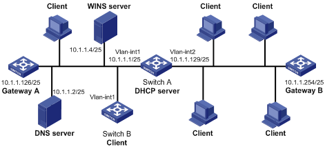
l The IP addresses of VLAN-interface 1 and VLAN-interface 2 on Switch A are 10.1.1.1/25 and 10.1.1.129/25 respectively.
l In the address pool 10.1.1.0/25, the address lease duration is ten days and twelve hours, domain name suffix aabbcc.com, DNS server address 10.1.1.2, gateway 10.1.1.126, and WINS server 10.1.1.4.
l In the address pool 10.1.1.128/25, the address lease duration is five days, domain name suffix aabbcc.com, DNS server address 10.1.1.2, and gateway address 10.1.1.254, and there is no WINS server address.
![]()
If you use the inheriting relation of parent and child address pools, make sure that the number of the assigned IP addresses does not exceed the number of the IP addresses in the child address pool; otherwise extra IP addresses will be obtained from the parent address pool, and the attributes (for example, gateway) also are based on the configuration of the parent address pool.
For example, in the network to which VLAN-interface 1 is connected, if multiple clients apply for IP addresses, the child address pool 10.1.1.0/25 assigns IP addresses first. When the IP addresses in the child address pool have been assigned, if other clients need IP addresses, the IP addresses will be assigned from the parent address pool 10.1.1.0/24 and the attributes will be based on the configuration of the parent address pool.
For this example, the number of clients applying for IP addresses from VLAN-interface 1 is recommended to be less than or equal to 122 and the number of clients applying for IP addresses from VLAN-interface 2 is recommended to be less than or equal to 124.
Network diagram
Figure 2-1 Network diagram for DHCP configuration
Configuration procedure
1) Configure a VLAN and add a port in this VLAN, and then configure the IP address of the VLAN interface (omitted).
2) Configure DHCP service.
# Enable DHCP.
<SwitchA> system-view
[SwitchA] dhcp enable
# Configure the IP addresses that are not dynamically assigned. (That is, the IP addresses of the DNS server, WINS server, and gateways.)
[SwitchA] dhcp server forbidden-ip 10.1.1.2
[SwitchA] dhcp server forbidden-ip 10.1.1.4
[SwitchA] dhcp server forbidden-ip 10.1.1.126
[SwitchA] dhcp server forbidden-ip 10.1.1.254
# Configure DHCP address pool 0, including address range, domain name suffix of the clients, and domain name server address.
[SwitchA] dhcp server ip-pool 0
[SwitchA-dhcp-pool-0] network 10.1.1.0 mask 255.255.255.0
[SwitchA-dhcp-pool-0] domain-name aabbcc.com
[SwitchA-dhcp-pool-0] dns-list 10.1.1.2
[SwitchA-dhcp-pool-0] quit
# Configure DHCP address pool 1, including address range, gateway, WINS server address and lease time.
[SwitchA] dhcp server ip-pool 1
[SwitchA-dhcp-pool-1] network 10.1.1.0 mask 255.255.255.128
[SwitchA-dhcp-pool-1] gateway-list 10.1.1.126
[SwitchA-dhcp-pool-1] expired day 10 hour 12
[SwitchA-dhcp-pool-1] nbns-list 10.1.1.4
[SwitchA-dhcp-pool-1] quit
# Configure DHCP address pool 2, including address range, gateway and lease time.
[SwitchA] dhcp server ip-pool 2
[SwitchA-dhcp-pool-2] network 10.1.1.128 mask 255.255.255.128
[SwitchA-dhcp-pool-2] expired day 5
[SwitchA-dhcp-pool-2] gateway-list 10.1.1.254
DHCP Server with Option 184 Support Configuration Example
Network requirements
A 3COM VCX device operating as a DHCP client requests the DHCP server for all sub-options of Option 184. An H3C series switch operates as the DHCP server. The Option 184 support function is configured for a global DHCP address pool. The sub-options of Option 184 are as follows:
l NCP-IP: 3.3.3.3
l AS-IP: 2.2.2.2
l Voice VLAN configuration: voice VLAN: enabled; voice VLAN ID: 3
l Fail-over routing: IP address: 1.1.1.1; dialer string: 99*
Network diagram
Figure 2-2 Network diagram for Option 184 support configuration
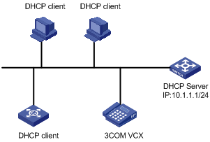
Configuration procedure
1) Configure the DHCP client.
Configure the 3COM VCX device to operate as a DHCP client and to request for all sub-options of Option 184. (Configuration process omitted)
2) Configure the DHCP server.
# Enter system view.
<Sysname> system-view
# Add Ethernet 1/0/1 to VLAN 2 and configure the IP address of VLAN 2 interface to be 10.1.1.1/24.
[Sysname] vlan 2
[Sysname-vlan2] port Ethernet 1/0/1
[Sysname-vlan2] quit
[Sysname] interface Vlan-interface 2
[Sysname-Vlan-interface2] ip address 10.1.1.1 255.255.255.0
[Sysname-Vlan-interface2] quit
# Configure VLAN-interface 2 to operate in the DHCP server mode.
[Sysname] dhcp select global interface Vlan-interface 2
# Enter DHCP address pool view.
[Sysname] dhcp server ip-pool 123
# Configure sub-options of Option 184 in global DHCP address pool view.
[Sysname-dhcp-pool-123] network 10.1.1.1 mask 255.255.255.0
[Sysname-dhcp-pool-123] voice-config ncp-ip 3.3.3.3
[Sysname-dhcp-pool-123] voice-config as-ip 2.2.2.2
[Sysname-dhcp-pool-123] voice-config voice-vlan 3 enable
[Sysname-dhcp-pool-123] voice-config fail-over 1.1.1.1 99*
DHCP Accounting Configuration Example
Network requirements
l The DHCP server connects to a DHCP client and a RADIUS server respectively through Ethernet 1/0/1 and Ethernet 1/0/2.
l Ethernet 1/0/1 belongs to VLAN 2; Ethernet 1/0/2 belongs to VLAN 3.
l The IP address of VLAN-interface 1 is 10.1.1.1/24, and that of VLAN-interface 2 is 10.1.2.1/24.
l The IP address of the RADIUS server is 10.1.2.2/24.
l DHCP accounting is enabled on the DHCP server.
l The IP addresses of the global DHCP address pool belongs to the network segment 10.1.1.0. The DHCP server operates as a RADIUS client and adopts AAA for authentication.
Network diagram
Figure 2-3 Network diagram for DHCP accounting configuration
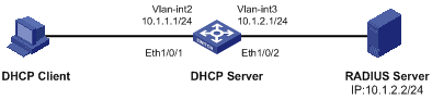
Configuration procedure
# Enter system view.
<Sysname> system-view
# Create VLAN 2.
[Sysname] vlan 2
[Sysname-vlan2] quit
# Create VLAN 3.
[Sysname] vlan 3
[Sysname-vlan3] quit
# Enter Ethernet 1/0/1 port view and add the port to VLAN 2.
[Sysname] interface Ethernet 1/0/1
[Sysname-Ethernet1/0/1] port access vlan 2
[Sysname-Ethernet1/0/1] quit
# Enter Ethernet 1/0/2 port view and add the port to VLAN 3.
[Sysname] interface Ethernet 1/0/2
[Sysname-Ethernet1/0/2] port access vlan 3
[Sysname-Ethernet1/0/2] quit
# Enter VLAN 2 interface view and assign the IP address 10.1.1.1/24 to the VLAN interface.
[Sysname] interface Vlan-interface 2
[Sysname-Vlan-interface2] ip address 10.1.1.1 24
[Sysname-Vlan-interface2] quit
# Enter VLAN 3 interface view and assign the IP address 10.1.2.1/24 to the VLAN interface.
[Sysname] interface Vlan-interface 3
[Sysname-Vlan-interface3] ip address 10.1.2.1 24
[Sysname-Vlan-interface3] quit
# Create a domain and a RADIUS scheme. Associate the domain with the RADIUS scheme.
[Sysname] radius scheme 123
[Sysname-radius-123] primary authentication 10.1.2.2
[Sysname-radius-123] primary accounting 10.1.2.2
[Sysname] domain 123
[Sysname-isp-123] scheme radius-scheme 123
[Sysname-isp-123] quit
# Create an address pool on the DHCP server.
[Sysname] dhcp server ip-pool test
[Sysname-dhcp-pool-test] network 10.1.1.0 mask 255.255.255.0
# Enable DHCP accounting.
[Sysname-dhcp-pool-test] accounting domain 123
Troubleshooting a DHCP Server
Symptom
The IP address dynamically assigned by a DHCP server to a client conflicts with the IP address of another host.
Analysis
With DHCP enabled, IP address conflicts are usually caused by IP addresses that are manually configured on hosts.
Solution
l Disconnect the DHCP client from the network and then check whether there is a host using the conflicting IP address by performing ping operation on another host on the network, with the conflicting IP address as the destination and an enough timeout time.
l The IP address is manually configured on a host if you receive a response packet of the ping operation. You can then disable the IP address from being dynamically assigned by using the dhcp server forbidden-ip command on the DHCP server.
l Attach the DHCP client to the network, release the dynamically assigned IP address and obtain an IP address again. For example, enter DOS by executing the cmd command in Windows XP, and then release the IP address by executing the ipconfig/release command. Then obtain an IP address again by executing the ipconfig/renew command.
When configuring the DHCP relay agent, go to these sections for information you are interested in:
l Introduction to DHCP Relay Agent
l Configuring the DHCP Relay Agent
l Displaying and Maintaining DHCP Relay Agent Configuration
l DHCP Relay Agent Configuration Example
l Troubleshooting DHCP Relay Agent Configuration
Currently, the interface-related DHCP relay agent configurations can only be made on VLAN interfaces.
Introduction to DHCP Relay Agent
Usage of DHCP Relay Agent
Since the packets are broadcasted in the process of obtaining IP addresses, DHCP is only applicable to the situation that DHCP clients and DHCP servers are in the same network segment, that is, you need to deploy at least one DHCP server for each network segment, which is far from economical.
DHCP relay agent is designed to address this problem. It enables DHCP clients in a subnet to communicate with the DHCP server in another subnet so that the DHCP clients can obtain IP addresses. In this case, the DHCP clients in multiple networks can use the same DHCP server, which can decrease your cost and provide a centralized administration.
DHCP Relay Agent Fundamentals
Figure 3-1 illustrates a typical DHCP relay agent application.
Figure 3-1 Typical DHCP relay agent application

In the process of dynamic IP address assignment through the DHCP relay agent, the DHCP client and DHCP server interoperate with each other in a similar way as they do without the DHCP relay agent. The following sections only describe the forwarding process of the DHCP relay agent. For the interaction process of the packets, see section Obtaining IP Addresses Dynamically.
1) After receiving the DHCP-DISCOVER or DHCP-REQUEST broadcast from the client, the network device providing the DHCP relay agent function unicasts the message to the designated DHCP server based on the configuration.
2) The DHCP server selects an IP address and other parameters and sends the configuration information to the DHCP relay agent that relays the information to the client (the sending mode is decided by the flag filed in the client’s DHCP-DISCOVER packet, refer to section DHCP Packet Format for details).
Option 82 Support on DHCP Relay Agent
Introduction to Option 82
Option 82 is the relay agent information option in the DHCP message. It records the location information of the DHCP client. With this option, the administrator can locate the DHCP client to further implement security control and accounting. The Option 82 supporting server can also use such information to define individual assignment policies of IP address and other parameters for the clients.
Option 82 involves at most 255 sub-options. If Option 82 is defined, at least one sub-option must be defined. Currently the DHCP relay agent supports two sub-options: sub-option 1 (circuit ID sub-option) and sub-option 2 (remote ID sub-option).
Padding content of Option 82
Option 82 has no unified definition in RFC 3046. Its padding information varies with vendors. Currently, S3600 Series Ethernet Switches that operate as DHCP relay agents support the extended padding format of Option 82 sub-options. By default, the sub-options of Option 82 are padded as follows, as shown in Figure 3-2 and Figure 3-3. (The content in brackets is the fixed value of each field.)
l sub-option 1: Padded with the port index (smaller than the physical port number by 1) and VLAN ID of the port that received the client’s request.
l sub-option 2: Padded with the bridge MAC address of the DHCP relay agent device that received the client’s request.
Figure 3-2 Padding contents for sub-option 1 of Option 82
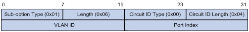
Figure 3-3 Padding contents for sub-option 2 of Option 82
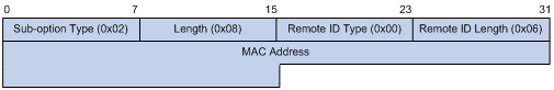
Mechanism of Option 82 supported on DHCP relay agent
The procedure for a DHCP client to obtain an IP address from a DHCP server through a DHCP relay agent is similar to that for the client to obtain an IP address from a DHCP server directly. The following are the mechanism of Option 82 support on DHCP relay agent.
1) Upon receiving a DHCP request, the DHCP relay agent checks whether the packet contains Option 82 and processes the packet accordingly.
l If the request packet contains Option 82, the DHCP relay agent processes the packet depending on the configured strategy (that is, discards the packet, replaces the original Option 82 in the packet with its own, or leaves the original Option 82 unchanged in the packet), and forwards the packet (if not discarded) to the DHCP server.
l If the request packet does not contain Option 82, the DHCP relay agent adds Option 82 to the packet and forwards the packet to the DHCP server.
2) Upon receiving the packet returned from the DHCP server, the DHCP relay agent strips Option 82 from the packet and forwards the packet with the DHCP configuration information to the DHCP client.
![]()
Request packets sent by a DHCP client fall into two categories: DHCP-DISCOVER packets and DHCP-REQUEST packets. As DHCP servers coming from different manufacturers process DHCP request packets in different ways (that is, some DHCP servers process Option 82 in DHCP-DISCOVER packets, whereas the rest process Option 82 in DHCP-REQUEST packets), a DHCP relay agent adds Option 82 to both types of packets to accommodate to DHCP servers of different manufacturers.
Configuring the DHCP Relay Agent
![]()
If a switch belongs to an IRF fabric, you need to enable the UDP Helper function on it before configuring it as a DHCP relay agent.
DHCP Relay Agent Configuration Task List
Complete the following tasks to configure the DHCP relay agent:
|
Task |
Remarks |
|
Required |
|
|
Correlating a DHCP Server Group with a Relay Agent Interface |
Required |
|
Optional |
|
|
Optional |
Enabling DHCP
Make sure to enable DHCP before you perform other DHCP relay-related configurations, since other DHCP-related configurations cannot take effect with DHCP disabled.
Follow these steps to enable DHCP:
|
To do… |
Use the command… |
Remarks |
|
Enter system view |
system-view |
— |
|
Enable DHCP |
dhcp enable |
Required Enabled by default. |
Note that: Among S3600 series switches, only S3600-EI switches support this command. DHCP is always enabled on S3600-SI series switches.
Correlating a DHCP Server Group with a Relay Agent Interface
To enhance reliability, you can set multiple DHCP servers on the same network. These DHCP servers form a DHCP server group. When an interface of the relay agent establishes a correlation with the DHCP server group, the interface will forward received DHCP packets to all servers in the server group.
Follow these steps to correlate a DHCP server group with a relay agent interface:
|
To do… |
Use the command… |
Remarks |
|
Enter system view |
system-view |
— |
|
Configure the DHCP server IP address(es) in a specified DHCP server group |
dhcp-server groupNo ip ip-address&<1-8> |
Required By default, no DHCP server IP address is configured in a DHCP server group. |
|
Map an interface to a DHCP server group |
interface interface-type interface-number |
Required By default, a VLAN interface is not mapped to any DHCP server group. |
|
dhcp-server groupNo |
![]()
To improve security and avoid malicious attack to the unused SOCKETs, S3600 Ethernet switches provide the following functions:
l UDP 67 and UDP 68 ports used by DHCP are enabled only when DHCP is enabled.
l UDP 67 and UDP 68 ports are disabled when DHCP is disabled.
The corresponding implementation is as follows:
l When a VLAN interface is mapped to a DHCP server group with the dhcp-server command, the DHCP relay agent is enabled. At the same time, UDP 67 and UDP 68 ports used by DHCP are enabled.
l When the mapping between a VLAN interface and a DHCP server group is removed with the undo dhcp-server command, DHCP services are disabled. At the same time, UDP 67 and UDP 68 ports are disabled.
![]()
l You can configure up to eight DHCP server IP addresses in a DHCP server group.
l You can map multiple VLAN interfaces to one DHCP server group. But one VLAN interface can be mapped to only one DHCP server group.
l If you execute the dhcp-server groupNo command repeatedly, the new configuration overwrites the previous one.
l You need to configure the group number specified in the dhcp-server groupNo command in VLAN interface view by using the command dhcp-server groupNo ip ip-address&<1-8> in advance.
Configuring DHCP Relay Agent Security Functions
Configuring address checking
![]()
Among S3600 series switches, only S3600-EI series switches support the DHCP relay agent address checking function.
After relaying an IP address from the DHCP server to a DHCP client, the DHCP relay agent can automatically record the client’s IP-to-MAC binding and generate a dynamic address entry. It also supports static bindings, which means you can manually configure IP-to-MAC bindings on the DHCP relay agent, so that users can access external network using fixed IP addresses.
The purpose of the address checking function on DHCP relay agent is to prevent unauthorized users from statically configuring IP addresses to access external networks. With this function enabled, a DHCP relay agent inhibits a user from accessing external networks if the IP address configured on the user end and the MAC address of the user end do not match any entries (including the entries dynamically tracked by the DHCP relay agent and the manually configured static entries) in the user address table on the DHCP relay agent.
Follow these steps to configure address checking:
|
To do… |
Use the command… |
Remarks |
|
Enter system view |
system-view |
— |
|
Create a static IP-to-MAC binding |
dhcp-security static ip-address mac-address |
Optional Not created by default. (Only S3600-EI series switches among S3600 series switches support this configuration.) |
|
Enter interface view |
interface interface-type interface-number |
— |
|
Enable the address checking function |
address-check enable |
Required Disabled by default. (Only S3600-EI series switches among S3600 series switches support this configuration.) |
![]()
l The address-check enable command is independent of other commands of the DHCP relay agent. That is, the invalid address check takes effect when this command is executed, regardless of whether other commands (such as the command to enable DHCP) are used.
l Before executing the address-check enable command on the interface connected to the DHCP server, you need to configure the static binding of the IP address to the MAC address of the DHCP server. Otherwise, the DHCP client will fail to obtain an IP address.
Configuring the dynamic client address entry updating function
![]()
Among S3600 series switches, only S3600-EI series switches support the DHCP relay agent handshake and dynamic client address entry updating functions.
After relaying an IP address from the DHCP server to the DHCP client, the DHCP relay agent can automatically record the client’s IP-to-MAC binding and generate a dynamic address entry. But as a DHCP relay agent does not process DHCP-RELEASE packets, which are sent to DHCP servers by DHCP clients through unicast when the DHCP clients release IP addresses, the user address entries maintained by the DHCP cannot be updated in time. You can solve this problem by enabling the DHCP relay agent handshake function and configuring the dynamic client address entry updating interval.
After the handshake function is enabled, the DHCP relay agent sends the handshake packet (the DHCP-REQUEST packet) periodically to the DHCP server using a client’s IP address and its own MAC address.
l If the DHCP relay agent receives the DHCP-ACK packet from the DHCP server, or receives no response from the server within a specified period, the IP address can be assigned. The DHCP relay agent ages out the corresponding entry in the client address table.
l If the DHCP relay agent receives the DHCP-NAK packet from the DHCP server, the lease of the IP address does not expire. The DHCP relay agent does not age out the corresponding entry.
Follow these steps to configure the dynamic user address entry updating function:
|
To do… |
Use the command… |
Remarks |
|
Enter system view |
system-view |
— |
|
Enable the DHCP relay agent handshake function |
dhcp relay hand enable |
Optional Enabled by default. (Only S3600-EI series switches among S3600 series switches support this configuration.) |
|
Set the interval at which the DHCP relay agent dynamically updates the client address entries |
dhcp-security tracker { interval | auto } |
Optional By default, auto is adopted, that is, the interval is automatically calculated. (Only S3600-EI series switches among S3600 series switches support this configuration.) |
![]()
Currently, the DHCP relay agent handshake function on a S3600-EI series switch can only interoperate with a Windows 2000 DHCP server.
Enabling unauthorized DHCP server detection
If there is an unauthorized DHCP server in the network, when a client applies for an IP address, the unauthorized DHCP server may assign an incorrect IP address to the DHCP client.
With this feature enabled, upon receiving a DHCP message with the siaddr field (IP addresses of the servers offering IP addresses to the client) not being 0 from a client, the DHCP relay agent will record the value of the siaddr field and the receiving interface. The administrator can use this information to check out any DHCP unauthorized servers.
Follow these steps to enable unauthorized DHCP server detection:
|
To do… |
Use the command… |
Remarks |
|
Enter system view |
system-view |
— |
|
Enable unauthorized DHCP server detection |
dhcp-server detect |
Required Disabled by default. |
![]()
With the unauthorized DHCP server detection enabled, the relay agent will log all DHCP servers, including authorized ones, and each server is recorded only once until such information is removed and is recorded again. The administrator needs to find unauthorized DHCP servers from the system log information.
Configuring the DHCP Relay Agent to Support Option 82
Prerequisites
Before configuring Option 82 support on a DHCP relay agent, you need to:
l Configure network parameters and relay function of the DHCP relay device.
l Perform assignment strategy-related configurations, such as network parameters of the DHCP server, address pool, and lease time.
l The routes between the DHCP relay agent and the DHCP server are reachable.
Enabling Option 82 support on a DHCP relay agent
Follow these steps to enable Option 82 support on a DHCP relay agent:
|
To do… |
Use the command… |
Remarks |
|
Enter system view |
system-view |
— |
|
Enable Option 82 support on the DHCP relay agent |
dhcp relay information enable |
Required Disabled by default. |
|
Configure the strategy for the DHCP relay agent to process request packets containing Option 82 |
dhcp relay information strategy { drop | keep | replace } |
Optional By default, the replace strategy is adopted |
l By default, with the Option 82 support function enabled on the DHCP relay agent, the DHCP relay agent will adopt the replace strategy to process the request packets containing Option 82. However, if other strategies are configured before, then enabling the 82 support on the DHCP relay agent will not change the configured strategies.
l To enable Option 82, you need to perform the corresponding configuration on the DHCP server and the DHCP relay agent.
Displaying and Maintaining DHCP Relay Agent Configuration
|
To do… |
Use the command… |
Remarks |
|
Display the information about a specified DHCP server group |
display dhcp-server groupNo |
Available in any view |
|
Display the information about the DHCP server group to which a specified VLAN interface is mapped |
display dhcp-server interface Vlan-interface vlan-id |
|
|
Display the specified client address entries on the DHCP relay agent |
display dhcp-security [ ip-address | dynamic | static | tracker ] |
|
|
Clear the statistics information of the specified DHCP server group |
reset dhcp-server groupNo |
Available in user view |
![]()
Among S3600 series Ethernet switches, only S3600-EI series switches support the display dhcp-security command.
DHCP Relay Agent Configuration Example
Network requirements
VLAN-interface 1 on the DHCP relay agent (Switch A) connects to the network where DHCP clients reside. The IP address of VLAN-interface 1 is 10.10.1.1/24 and IP address of VLAN-interface 2 is 10.1.1.2/24 that communicates with the DHCP server 10.1.1.1/24. As shown in the figure below, Switch A forwards messages between DHCP clients and the DHCP server to assign IP addresses in subnet 10.10.1.0/24 to the clients.
Network diagram
Figure 3-4 Network diagram for DHCP relay agent
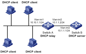
Configuration procedure
# Create DHCP server group 1 and configure an IP address of 10.1.1.1 for it.
<SwitchA> system-view
[SwitchA] dhcp-server 1 ip 10.1.1.1
# Map VLAN-interface 1 to DHCP server group 1.
[SwitchA] interface Vlan-interface 1
[SwitchA-Vlan-interface1] dhcp-server 1
![]()
l You need to perform corresponding configurations on the DHCP server to enable the DHCP clients to obtain IP addresses from the DHCP server. The DHCP server configurations vary with different DHCP server devices, so the configurations are omitted.
l The DHCP relay agent and DHCP server must be reachable to each other.
Troubleshooting DHCP Relay Agent Configuration
Symptom
A client fails to obtain configuration information through a DHCP relay agent.
Analysis
This problem may be caused by improper DHCP relay agent configuration. When a DHCP relay agent operates improperly, you can locate the problem by enabling debugging and checking the information about debugging and interface state (You can display the information by executing the corresponding display command.)
Solution
l Check if DHCP is enabled on the DHCP server and the DHCP relay agent.
l Check if an address pool that is on the same network segment with the DHCP clients is configured on the DHCP server.
l Check if a reachable route is configured between the DHCP relay agent and the DHCP server.
l Check the DHCP relay agent. Check if the correct DHCP server group is configured on the interface connecting the network segment where the DHCP client resides. Check if the IP address of the DHCP server group is correct.
l If the address-check enable command is configured on the interface connected to the DHCP server, verify the DHCP server’s IP-to-MAC address binding entry is configured on the DHCP relay agent; otherwise the DHCP client cannot obtain an IP address.
When configuring DHCP snooping, go to these sections for information you are interested in:
l DHCP Snooping Configuration Examples
l Displaying DHCP Snooping Configuration
DHCP Snooping Overview
Introduction to DHCP Snooping
For the sake of security, the IP addresses used by online DHCP clients need to be tracked for the administrator to verify the corresponding relationship between the IP addresses the DHCP clients obtained from DHCP servers and the MAC addresses of the DHCP clients.
l Switches can track DHCP clients’ IP addresses through the security function of the DHCP relay agent operating at the network layer.
l Switches can track DHCP clients’ IP addresses through the DHCP snooping function at the data link layer.
When an unauthorized DHCP server exists in the network, a DHCP client may obtains an illegal IP address. To ensure that the DHCP clients obtain IP addresses from valid DHCP servers, you can specify a port to be a trusted port or an untrusted port by the DHCP snooping function.
l Trusted: A trusted port is connected to an authorized DHCP server directly or indirectly. It forwards DHCP messages to guarantee that DHCP clients can obtain valid IP addresses.
l Untrusted: An untrusted port is connected to an unauthorized DHCP server. The DHCP-ACK or DHCP-OFFER packets received from the port are discarded, preventing DHCP clients from receiving invalid IP addresses.
Figure 4-1 illustrates a typical network diagram for DHCP snooping application, where Switch A is an S3600 series Ethernet switch.
Figure 4-1 Typical network diagram for DHCP snooping application
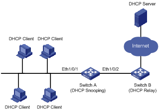
DHCP snooping listens the following two types of packets to retrieve the IP addresses the DHCP clients obtain from DHCP servers and the MAC addresses of the DHCP clients:
l DHCP-REQUEST packet
l DHCP-ACK packet
Introduction to DHCP-Snooping Option 82
Introduction to Option 82
For details about Option 82, refer to Option 82 Support on DHCP Relay Agent.
Padding content and frame format of Option 82
There is no specification for what should be padded in Option 82. Manufacturers can pad it as required. By default, the sub-options of Option 82 for S3600 Series Ethernet Switches (enabled with DHCP snooping) are padded as follows:
l sub-option 1 (circuit ID sub-option): Padded with the port index (smaller than the physical port number by 1) and VLAN ID of the port that received the client’s request.
l sub-option 2 (remote ID sub-option): Padded with the bridge MAC address of the DHCP snooping device that received the client’s request.
By default, when S3600 Series Ethernet Switches serve as DHCP snooping devices, Option 82 adopts the extended format. Refer to Figure 4-2 and Figure 4-3 for the extended format of the sub-options (with the default padding contents). That is, the circuit ID or remote ID sub-option defines the type and length of a circuit ID or remote ID.
The remote ID type field and circuit ID type field are determined by the option storage format. They are both set to 0 in the case of HEX format and to 1 in the case of ASCII format.
Figure 4-2 Extended format of the circuit ID sub-option
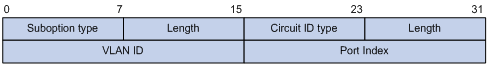
Figure 4-3 Extended format of the remote ID sub-option
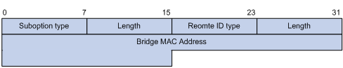
In practice, some network devices do not support the type and length identifiers of the Circuit ID and Remote ID sub-options. To interwork with these devices, S3600 Series Ethernet Switches support Option 82 in the standard format. Refer to Figure 4-4 and Figure 4-5 for the standard format of the sub-options (with the default padding contents). In the standard format, the Circuit ID or Remote ID sub-option does not contain the two-byte type and length fields of the circuit ID or remote ID.
Figure 4-4 Standard format of the circuit ID sub-option
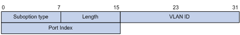
Figure 4-5 Standard format of the remote ID sub-option
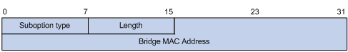
Mechanism of DHCP-snooping Option 82
With DHCP snooping and DHCP-snooping Option 82 support enabled, when the DHCP snooping device receives a DHCP client’s request containing Option 82, it will handle the packet according to the handling policy and the configured contents in sub-options. For details, see Table 4-1.
Table 4-1 Ways of handling a DHCP packet with Option 82
|
Handling policy |
Sub-option configuration |
The DHCP Snooping device will… |
|
Drop |
— |
Drop the packet. |
|
Keep |
— |
Forward the packet without changing Option 82. |
|
Replace |
Neither of the two sub-options is configured |
Forward the packet after replacing the original Option 82 with the default content. The storage format of Option 82 content is the one specified with the dhcp-snooping information format command or the default HEX format if this command is not executed. |
|
Circuit ID sub-option is configured |
Forward the packet after replacing the circuit ID sub-option of the original Option 82 with the configured circuit ID sub-option in ASCII format. |
|
|
Remote ID sub-option is configured |
Forward the packet after replacing the remote ID sub-option of the original Option 82 with the configured remote ID sub-option in ASCII format. |
When receiving a DHCP client’s request without Option 82, the DHCP snooping device will add the option field with the configured sub-option and then forward the packet. For details, see Table 4-2.
Table 4-2 Ways of handling a DHCP packet without Option 82
|
Sub-option configuration |
The DHCP-Snooping device will … |
|
Neither of the two sub-options is configured. |
Forward the packet after adding Option 82 with the default contents. The format of Option 82 is the one specified with the dhcp-snooping information format command or the default HEX format if this command is not executed. |
|
Circuit ID sub-option is configured. |
Forward the packet after adding Option 82 with the configured circuit ID sub-option in ASCII format. |
|
Remote ID sub-option is configured. |
Forward the packet after adding Option 82 with the configured remote ID sub-option in ASCII format. |
![]()
The circuit ID and remote ID sub-options in Option 82, which can be configured simultaneously or separately, are independent of each other in terms of configuration sequence.
When the DHCP snooping device receives a DHCP response packet from the DHCP server, the DHCP snooping device will delete the Option 82 field, if contained, before forwarding the packet, or will directly forward the packet if the packet does not contain the Option 82 field.
Introduction to IP Filtering
A denial-of-service (DoS) attack means an attempt of an attacker sending a large number of forged address requests with different source IP addresses to the server so that the network cannot work normally. The specific effects are as follows:
l The resources on the server are exhausted, so the server does not respond to other requests.
l After receiving such type of packets, a switch needs to send them to the CPU for processing. Too many request packets cause high CPU usage rate. As a result, the CPU cannot work normally.
l The switch can filter invalid IP packets through the DHCP-snooping table and IP static binding table.
DHCP-snooping table
After DHCP snooping is enabled on a switch, a DHCP-snooping table is generated. It is used to record IP addresses obtained from the DHCP server, MAC addresses, the number of the port through which a client is connected to the DHCP-snooping-enabled device, and the number of the VLAN to which the port belongs to. These records are saved as entries in the DHCP-snooping table.
IP static binding table
The DHCP-snooping table only records information about clients that obtains IP address dynamically through DHCP. If a fixed IP address is configured for a client, the IP address and MAC address of the client cannot be recorded in the DHCP-snooping table. Consequently, this client cannot pass the IP filtering of the DHCP-snooping table, thus it cannot access external networks.
To solve this problem, the switch supports the configuration of static binding table entries, that is, the binding relationship between IP address, MAC address, and the port connecting to the client, so that packets of the client can be correctly forwarded.
IP filtering
The switch can filter IP packets in the following two modes:
l Filtering the source IP address in a packet. If the source IP address and the number of the port that receives the packet are consistent with entries in the DHCP-snooping table or static binding table, the switch regards the packet as a valid packet and forwards it; otherwise, the switch drops it directly.
l Filtering the source IP address and the source MAC address in a packet. If the source IP address and source MAC address in the packet, and the number of the port that receives the packet are consistent with entries in the DHCP-snooping table or static binding table, the switch regards the packet as a valid packet and forwards it; otherwise, the switch drops it directly.
Configuring DHCP Snooping
Configuring DHCP Snooping
Follow these steps to configure DHCP snooping:
|
To do… |
Use the command… |
Remarks |
|
Enter system view |
system-view |
— |
|
Enable DHCP snooping |
dhcp-snooping |
Required By default, the DHCP snooping function is disabled. |
|
Enter Ethernet port view |
interface interface-type interface-number |
— |
|
Specify the current port as a trusted port |
dhcp-snooping trust |
Required By default, after DHCP snooping is enabled, all ports of a switch are untrusted ports. |
![]()
l If an S3600 Ethernet switch is enabled with DHCP snooping, the clients connected to it cannot dynamically obtain IP addresses through BOOTP.
l You need to specify the ports connected to the valid DHCP servers as trusted to ensure that DHCP clients can obtain valid IP addresses. The trusted port and the port connected to the DHCP client must be in the same VLAN.
l To enable DHCP snooping on an S3600 switch that belongs to an IRF fabric, set the fabric ports on all devices in the fabric to DHCP snooping trusted ports to ensure that the clients connected to each device can obtain IP addresses. In this case, do not configure the ports connecting to the DHCP clients and DHCP server to belong to different units of the fabric; otherwise, the switch cannot record DHCP snooping entries although the clients can obtain IP addresses.
l You are not recommended to configure both the DHCP snooping and selective Q-in-Q function on the switch, which may result in the DHCP snooping to function abnormally.
Configuring DHCP Snooping to Support Option 82
![]()
Enable DHCP snooping and specify trusted ports on the switch before configuring DHCP snooping to support Option 82.
Complete the following tasks to configure the DHCP snooping to support Option 82:
|
Task |
Remarks |
|
Required |
|
|
Configuring a handling policy for DHCP packets with Option 82 |
Optional |
|
Optional |
|
|
Optional |
|
|
Optional |
|
|
Optional |
Enabling DHCP-snooping Option 82 support
Follow these steps to enable DHCP-snooping Option 82 support:
|
To do… |
Use the command… |
Remarks |
|
Enter system view |
system-view |
— |
|
Enable DHCP-snooping Option 82 support |
dhcp-snooping information enable |
Required Disabled by default. |
Configuring a handling policy for DHCP packets with Option 82
Follow these steps to configure a handling policy for DHCP packets with Option 82:
|
To do… |
Use the command… |
Remarks |
|
Enter system view |
system-view |
— |
|
Configure a global handling policy for requests that contain Option 82 |
dhcp-snooping information strategy { drop | keep | replace } |
Optional The default handling policy is replace. |
|
Enter Ethernet port view |
interface interface-type interface-number |
— |
|
Configure a handling policy for requests that contain Option 82 received on the specified interface |
dhcp-snooping information strategy { drop | keep | replace } |
Optional The default policy is replace. |
![]()
If a handling policy is configured on a port, this configuration overrides the globally configured handling policy for requests received on this port, while the globally configured handling policy applies on those ports where a handling policy is not natively configured.
Configuring the storage format of Option 82
S3600 Series Ethernet Switches support the HEX or ASCII format for the Option 82 field.
Follow these steps to configure a storage format for the Option 82 field:
|
To do… |
Use the command… |
Remarks |
|
Enter system view |
system-view |
— |
|
Configure a storage format for the Option 82 field |
dhcp-snooping information format { hex | ascii } |
Optional By default, the format is hex. |
![]()
The dhcp-snooping information format command applies only to the default content of the Option 82 field. If you have configured the circuit ID or remote ID sub-option, the format of the sub-option is ASCII, instead of the one specified with the dhcp-snooping information format command.
Configuring the circuit ID sub-option
Follow these steps to configure the circuit ID sub-option:
|
To do… |
Use the command… |
Remarks |
|
Enter system view |
system-view |
— |
|
Enter Ethernet port view |
interface interface-type interface-number |
— |
|
Configure the circuit ID sub-option in Option 82 |
dhcp-snooping information [ vlan vlan-id ] circuit-id string string |
Optional By default, the circuit ID sub-option contains the VLAN ID and port index related to the port that receives DHCP request packets from DHCP clients |
![]()
l If you have configured a circuit ID with the vlan vlan-id argument specified, and the other one without the argument in Ethernet port view, the former circuit ID applies to the DHCP messages from the specified VLAN; while the latter one applies to DHCP messages from other VLANs.
l In a port aggregation group, you can use this command to configure the primary and member ports respectively. When Option 82 is added, however, the circuit ID sub-option is subject to the one configured on the primary port.
l The circuit ID sub-option configured on a port will neither be synchronized in the case of port aggregation nor support IRF .
Configuring the remote ID sub-option
You can configure the remote ID sub-option in system view or Ethernet port view:
l In system view, the remote ID takes effect on all interfaces. You can configure Option 82 as the system name (sysname) of the device or any customized character string in the ASCII format.
l In Ethernet port view, the remote ID takes effect only on the current interface. You can configure Option 82 as any customized character string in the ASCII format for different VLANs. That is to say, you can add different configuration rules for packets from different VLANs.
Follow these steps to configure the remote ID sub-option in Option 82:
|
To do… |
Use the command… |
Remarks |
|
Enter system view |
system-view |
— |
|
Configure the remote ID sub-option in system view |
dhcp-snooping information remote-id { sysname | string string } |
Optional By default, the remote ID sub-option is the MAC address of the DHCP snooping device that received the DHCP client’s request. |
|
Enter Ethernet port view |
interface interface-type interface-number |
— |
|
Configure the remote ID sub-option in Ethernet port view |
dhcp-snooping information [ vlan vlan-id ] remote-id string string |
Optional By default, the remote ID sub-option is the MAC address of the DHCP snooping device that received the client’s request. |
![]()
l If you configure a remote ID sub-option in both system view and on a port, the remote ID sub-option configured on the port applies when the port receives a packet, and the global remote ID applies to other interfaces that have no remote ID sub-option configured.
l If you have configured a remote ID with the vlan vlan-id argument specified, and the other one without the argument in Ethernet port view, the former remote ID applies to the DHCP messages from the specified VLAN, while the latter one applies to DHCP messages from other VLANs.
l In a port aggregation group, you can use this command to configure the primary and member ports respectively. When Option 82 is added, however, the remote ID is subject to the one configured on the primary port.
l The remote ID configured on a port will neither be synchronized in the case of port aggregation nor support IRF.
Configuring the padding format for Option 82
Follow these steps to configure the padding format for Option 82:
|
To do… |
Use the command… |
Remarks |
|
Enter system view |
system-view |
— |
|
Configure the padding format |
dhcp-snooping information packet-format { extended | standard } |
Optional By default, the padding format is in extended format. |
Configuring IP Filtering
Follow these steps to configure IP filtering:
|
To do… |
Use the command… |
Remarks |
|
Enter system view |
system-view |
— |
|
Enter Ethernet port view |
interface interface-type interface-number |
— |
|
Enable IP filtering |
ip check source ip-address [ mac-address ] |
Required By default, this function is disabled. |
|
Create a static binding |
ip source static binding ip-address ip-address [ mac-address mac-address ] |
Optional By default, no static binding entry is created. |
![]()
l Enable DHCP snooping and specify trusted ports on the switch before configuring IP filtering.
l You are not recommended to configure IP filtering on the ports of a fabric or an aggregation group.
l To create a static binding after IP filtering is enabled with the mac-address keyword specified on a port, the mac-address argument must be specified; otherwise, the packets sent from this IP address cannot pass the IP filtering.
l A static entry has a higher priority than the dynamic DHCP snooping entry that has the same IP address as the static one. That is, if the static entry is configured after the dynamic entry is recorded, the static entry overwrites the dynamic entry; if the static entry is configured before DHCP snooping is enabled, no DHCP client can obtain the IP address of the static entry, that is, the dynamic DHCP snooping entry cannot be generated.
l The VLAN ID of the IP static binding configured on a port is the VLAN ID of the port.
DHCP Snooping Configuration Examples
DHCP-Snooping Option 82 Support Configuration Example
Network requirements
As shown in Figure 4-6, Ethernet 1/0/5 of the switch is connected to the DHCP server, and Ethernet 1/0/1, Ethernet 1/0/2, and Ethernet 1/0/3 are respectively connected to Client A, Client B, and Client C.
l Enable DHCP snooping on the switch.
l Specify Ethernet 1/0/5 on the switch as a trusted port for DHCP snooping.
l Enable DHCP-snooping Option 82 support on the switch and set the remote ID field in Option 82 to the system name of the switch. Set the circuit ID sub-option to abcd in DHCP packets from VLAN 1 on Ethernet 1/0/3.
Network diagram
Figure 4-6 Network diagram for DHCP-snooping Option 82 support configuration
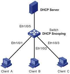
Configuration procedure
# Enable DHCP snooping on the switch.
<Switch> system-view
[Switch] dhcp-snooping
# Specify Ethernet 1/0/5 as the trusted port.
[Switch] interface Ethernet1/0/5
[Switch-Ethernet1/0/5] dhcp-snooping trust
[Switch-Ethernet1/0/5] quit
# Enable DHCP-snooping Option 82 support.
[Switch] dhcp-snooping information enable
# Set the remote ID sub-option in Option 82 to the system name (sysname) of the DHCP snooping device.
[Switch] dhcp-snooping information remote-id sysname
# Set the circuit ID sub-option in DHCP packets from VLAN 1 to abcd on Ethernet 1/0/3.
[Switch] interface Ethernet1/0/3
[Switch-Ethernet1/0/3] dhcp-snooping information vlan 1 circuit-id string abcd
IP Filtering Configuration Example
Network requirements
As shown in Figure 4-7, Ethernet 1/0/1 of the S3600 switch is connected to the DHCP server and Ethernet 1/0/2 is connected to Host A. The IP address and MAC address of Host A are 1.1.1.1 and 0001-0001-0001 respectively. Ethernet 1/0/3 and Ethernet 1/0/4 are connected to DHCP Client B and Client C.
l Enable DHCP snooping on the switch, and specify Ethernet 1/0/1 as the DHCP snooping trusted port.
l Enable IP filtering on Ethernet 1/0/2, Ethernet 1/0/3, and Ethernet 1/0/4 to prevent attacks to the server from clients using fake source IP addresses.
l Create static binding entries on the switch, so that Host A using a fixed IP address can access external networks.
Network diagram
Figure 4-7 Network diagram for IP filtering configuration
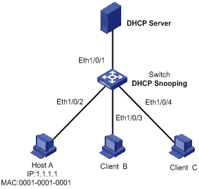
Configuration procedure
# Enable DHCP snooping on the switch.
<Switch> system-view
[Switch] dhcp-snooping
# Specify Ethernet 1/0/1 as the trusted port.
[Switch] interface Ethernet1/0/1
[Switch-Ethernet1/0/1] dhcp-snooping trust
[Switch-Ethernet1/0/1] quit
# Enable IP filtering on Ethernet 1/0/2, Ethernet 1/0/3, and Ethernet 1/0/4 to filter packets based on the source IP addresses/MAC addresses.
[Switch] interface Ethernet1/0/2
[Switch-Ethernet1/0/2] ip check source ip-address mac-address
[Switch-Ethernet1/0/2] quit
[Switch] interface Ethernet1/0/3
[Switch-Ethernet1/0/3] ip check source ip-address mac-address
[Switch-Ethernet1/0/3] quit
[Switch] interface Ethernet1/0/4
[Switch-Ethernet1/0/4] ip check source ip-address mac-address
[Switch-Ethernet1/0/4] quit
# Create static binding entries on Ethernet 1/0/2 of the switch.
[Switch] interface Ethernet1/0/2
[Switch-Ethernet1/0/2] ip source static binding ip-address 1.1.1.1 mac-address 0001-0001-0001
Displaying DHCP Snooping Configuration
|
To do… |
Use the command… |
Remarks |
|
Display the user IP-MAC address mapping entries recorded by the DHCP snooping function |
display dhcp-snooping [ unit unit-id ] |
Available in any view |
|
Display the (enabled/disabled) state of the DHCP snooping function and the trusted ports |
display dhcp-snooping trust |
|
|
Display the IP static binding table |
display ip source static binding [ vlan vlan-id | interface interface-type interface-number ] |
When configuring the DHCP packet rate limit function, go to these sections for information you are interested in:
l Introduction to DHCP Packet Rate Limit
l Configuring DHCP Packet Rate Limit
l Rate Limit Configuration Example
Introduction to DHCP Packet Rate Limit
To prevent ARP attacks and attacks from unauthorized DHCP servers, ARP packets and DHCP packets will be processed by the switch CPU for validity checking. But, if attackers generate a large number of ARP packets or DHCP packets, the switch CPU will be under extremely heavy load. As a result, the switch cannot work normally and even goes down.
S3600 series Ethernet switches support ARP and DHCP packet rate limit on a port and shut down the port under attack to prevent hazardous impact on the device CPU. For details about ARP packet rate limit, refer to ARP Operation in this manual. The following describes only the DHCP packet rate limit function.
After DHCP packet rate limit is enabled on an Ethernet port, the switch counts the number of DHCP packets received on this port per second. If the number of DHCP packets received per second exceeds the specified value, packets are passing the port at an over-high rate, which implies an attack to the port. In this case, the switch shuts down this port so that it cannot receive any packet, thus protect the switch from attacks.
In addition, the switch supports port state auto-recovery. After a port is shut down due to over-high packet rate, it resumes automatically after a configurable period of time.
![]()
When both port state auto-recovery interval for over-high ARP packet rate and port state auto-recovery interval for over-high DHCP packet rate are configured on a port, the shorter one will be the auto-recovery time.
Configuring DHCP Packet Rate Limit
Configuring DHCP Packet Rate Limit
Follow these steps to configure rate limit of DHCP packets:
|
To do… |
Use the command… |
Remarks |
|
Enter system view |
system-view |
— |
|
Enter port view |
interface interface-type interface-number |
— |
|
Enable the DHCP packet rate limit function |
dhcp rate-limit enable |
Required By default, DHCP packet rate limit is disabled. |
|
Configure the maximum DHCP packet rate allowed on the port |
dhcp rate-limit rate |
Optional By default, the maximum rate is 15 pps. |
|
Enable the port state auto-recovery function |
dhcp protective-down recover enable |
Optional By default, the port state auto-recovery function is disabled. |
|
Set the port state auto-recovery interval |
dhcp protective-down recover interval interval |
Optional The port state auto-recovery interval is 300 seconds. |
![]()
l Enable the port state auto-recovery function before setting the auto-recovery interval.
l You are not recommended to configure DHCP packet rate limit on the ports of an aggregation group.
Configuring Port State Auto Recovery
Follow these steps to configure port state auto recovery:
|
To do… |
Use the command… |
Remarks |
|
Enter system view |
system-view |
— |
|
Enable port state auto-recovery |
dhcp protective-down recover enable |
Required By default, this function is disabled. |
|
Configure the port state auto-recovery interval |
dhcp protective-down recover interval interval |
Optional By default, the auto-discovery interval is 300 seconds. |
Rate Limit Configuration Example
Network requirements
As shown in Figure 5-1, Ethernet 1/0/1 of the S3600 switch is connected to the DHCP server. Ethernet 1/0/2 is connected to client B and Ethernet 1/0/11 is connected to client A.
l Enable DHCP snooping on the switch, and specify Ethernet 1/0/1 as the DHCP snooping trusted port.
l Configure DHCP packet rate limit on Ethernet 1/0/11 and set the maximum DHCP packet rate allowed on the port to 100 pps.
l Set the port state auto-recovery interval to 30 seconds on the switch.
Networking diagram
Figure 5-1 Network diagram for DHCP packet rate limit configuration
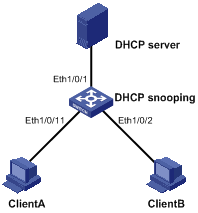
Configuration procedure
# Enable DHCP snooping on the switch.
<Switch> system-view
[Switch] dhcp-snooping
# Specify Ethernet 1/0/1 as the trusted port.
[Switch] interface Ethernet1/0/1
[Switch-Ethernet1/0/1] dhcp-snooping trust
[Switch-Ethernet1/0/1] quit
# Enable auto recovery.
[Sysname] dhcp protective-down recover enable
# Set the port state auto-recovery interval to 30 seconds.
[Sysname] dhcp protective-down recover interval 30
# Enter port view.
[Sysname] interface Ethernet 1/0/11
# Enable DHCP packet rate limit on Ethernet 1/0/11.
[Sysname-Ethernet1/0/11] dhcp rate-limit enable
# Set the maximum DHCP packet rate allowed on Ethernet 1/0/11 to 100 pps.
[Sysname-Ethernet1/0/11] dhcp rate-limit 100
When configuring the DHCP/BOOTP client, go to these sections for information you are interested in:
l Introduction to BOOTP Client
l Configuring a DHCP/BOOTP Client
l Displaying DHCP/BOOTP Client Configuration
Introduction to DHCP Client
After you specify a VLAN interface as a DHCP client, the device can use DHCP to obtain parameters such as IP address dynamically from the DHCP server, which facilitates user configuration and management.
Refer to Obtaining IP Addresses Dynamically for the process of how a DHCP client dynamically obtains an IP address through DHCP.
Introduction to BOOTP Client
After you specify an interface as a Bootstrap Protocol (BOOTP) client, the interface can use BOOTP to get information (such as IP address) from the BOOTP server, which simplifies your configuration.
Before using BOOTP, an administrator needs to configure a BOOTP parameter file for each BOOTP client on the BOOTP server. The parameter file contains information such as MAC address and IP address of a BOOTP client. When a BOOTP client sends a request to the BOOTP server, the BOOTP server will search for the BOOTP parameter file and return it to the client.
A BOOTP client dynamically obtains an IP address from a BOOTP server in the following way:
1) The BOOTP client broadcasts a BOOTP request, which contains its own MAC address.
2) The BOOTP server receives the request and searches for the corresponding IP address according to the MAC address of the BOOTP client and sends the information in a BOOTP response to the BOOTP client.
3) The BOOTP client obtains the IP address from the received response.
![]()
Because a DHCP server can interact with a BOOTP client, you can use the DHCP server to assign an IP address to the BOOTP client, without needing to configure any BOOTP server.
Configuring a DHCP/BOOTP Client
Follow these steps to configure a DHCP/BOOTP client:
|
To do… |
Use the command… |
Remarks |
|
Enter system view |
system-view |
— |
|
Enter VLAN interface view |
interface vlan-interface vlan-id |
— |
|
Configure the VLAN interface to obtain IP address through DHCP or BOOTP |
ip address { bootp-alloc | dhcp-alloc } |
Required By default, no IP address is configured for the VLAN interface. |
![]()
l Currently, an S3600 Ethernet switch functioning as the DHCP client can use an IP address for 24 days at most. That is, the DHCP client can obtain an address lease for no more than 24 days even though the DHCP server offers a longer lease period.
l If a switch belongs to an IRF fabric, you need to enable the UDP Helper function on the switch before configuring its VLAN interfaces to obtain IP addresses through DHCP.
![]()
To improve security and avoid malicious attack to the unused SOCKETs, S3600 Ethernet switches provide the following functions:
l UDP 67 and UDP 68 ports used by DHCP are enabled only when DHCP is enabled.
l UDP 67 and UDP 68 ports are disabled when DHCP is disabled.
The specific implementation is:
l Using the ip address dhcp-alloc command enables the DHCP client, and UDP port 68.
l Using the undo ip address dhcp-alloc command disables the DHCP client, and UDP port 68.
DHCP Client Configuration Example
Network requirements
Using DHCP, VLAN-interface 1 of Switch B is connected to the LAN to obtain an IP address from the DHCP server.
Network diagram
See Figure 2-1.
Configuration procedure
The following describes only the configuration on Switch B serving as a DHCP client.
# Configure VLAN-interface 1 to dynamically obtain an IP address by using DHCP.
<SwitchB> system-view
[SwitchB] interface Vlan-interface 1
[SwitchB-Vlan-interface1] ip address dhcp-alloc
BOOTP Client Configuration Example
Network requirement
Switch B’s port belonging to VLAN1 is connected to the LAN. VLAN-interface 1 obtains an IP address from the DHCP server by using BOOTP.
Network diagram
See Figure 2-1.
Configuration procedure
The following describes only the configuration on Switch B serving as a client.
# Configure VLAN-interface 1 to dynamically obtain an IP address from the DHCP server.
<SwitchB> system-view
[SwitchB] interface vlan-interface 1
[SwitchB-Vlan-interface1] ip address bootp-alloc
Displaying DHCP/BOOTP Client Configuration
|
To do… |
Use the command… |
Remarks |
|
Display related information on a DHCP client |
display dhcp client [ verbose ] |
Optional Available in any view |
|
Display related information on a BOOTP client |
display bootp client [ interface Vlan-interface vlan-id ] |