- Table of Contents
-
- H3C S3600 Operation Manual-Release 1602(V1.02)
- 00-1Cover
- 00-2Product Overview
- 01-CLI Operation
- 02-Login Operation
- 03-Configuration File Management Operation
- 04-VLAN Operation
- 05-IP Address and Performance Operation
- 06-Voice VLAN Operation
- 07-GVRP Operation
- 08-Port Basic Configuration Operation
- 09-Link Aggregation Operation
- 10-Port Isolation Operation
- 11-Port Security-Port Binding Operation
- 12-DLDP Operation
- 13-MAC Address Table Management Operation
- 14-Auto Detect Operation
- 15-MSTP Operation
- 16-Routing Protocol Operation
- 17-Multicast Operation
- 18-802.1x and System Guard Operation
- 19-AAA Operation
- 20-Web Authentication Operation
- 21-MAC Address Authentication Operation
- 22-VRRP Operation
- 23-ARP Operation
- 24-DHCP Operation
- 25-ACL Operation
- 26-QoS-QoS Profile Operation
- 27-Web Cache Redirection Operation
- 28-Mirroring Operation
- 29-IRF Fabric Operation
- 30-Cluster Operation
- 31-PoE-PoE Profile Operation
- 32-UDP Helper Operation
- 33-SNMP-RMON Operation
- 34-NTP Operation
- 35-SSH Operation
- 36-File System Management Operation
- 37-FTP-SFTP-TFTP Operation
- 38-Information Center Operation
- 39-System Maintenance and Debugging Operation
- 40-VLAN-VPN Operation
- 41-HWPing Operation
- 42-IPv6 Management Operation
- 43-DNS Operation
- 44-Smart Link-Monitor Link Operation
- 45-Access Management Operation
- 46-Appendix
- Related Documents
-
| Title | Size | Download |
|---|---|---|
| 31-PoE-PoE Profile Operation | 184.67 KB |
Table of Contents
PoE Features Supported by S3600
Enabling the PoE Feature on a Port
Setting the Maximum Output Power on a Port
Setting PoE Management Mode and PoE Priority of a Port
Setting the PoE Mode on a Port
Configuring the PD Compatibility Detection Function
Configuring PoE Over-Temperature Protection on the Switch
Upgrading the PSE Processing Software Online
Upgrading the PSE Processing Software of Fabric Switches Online
Displaying PoE Profile Configuration
PoE Profile Configuration Example
PoE Profile Application Example
When configuring PoE, go to these sections for information you are interested in:
![]()
The newly added function is upgrading the PoE module of the fabric switch remotely. See Upgrading the PSE Processing Software of Fabric Switches Online for details.
PoE Overview
Introduction to PoE
Power over Ethernet (PoE)-enabled devices use twisted pairs through electrical ports to supply power to the remote powered devices (PD) in the network and implement power supply and data transmission simultaneously.
Advantages of PoE
l Reliability: The centralized power supply provides backup convenience, unified management, and safety.
l Easy connection: Network terminals only require an Ethernet cable, but no external power supply.
l Standard: PoE conforms to the 802.3af standard and uses a globally uniform power interfaces;
l Bright application prospect: PoE can be applied to IP phones, wireless access points (APs), chargers for portable devices, card readers, network cameras, and data collection system.
PoE components
PoE consists of three components: power sourcing equipment (PSE), PD, and power interface (PI).
l PSE: PSE is comprised of the power and the PSE functional module. It can implement PD detection, PD power information collection, PoE, power supply monitoring, and power-off for devices.
l PD: PDs receive power from the PSE. PDs include standard PDs and nonstandard PDs. Standard PDs conform to the 802.3af standard, including IP phones, Wireless APs, network cameras and so on.
l PI: PIs are RJ45 interfaces which connect PSE/PDs to network cables.
PoE Features Supported by S3600
PoE-enabled S3600 series Ethernet switches include:
l S3600-28P-PWR-SI
l S3600-28P-PWR-EI
l S3600-52P-PWR-SI
l S3600-52P-PWR-EI
A PoE-enabled S3600 switch has the following features:
l As the PSE, it supports the IEEE802.3af standard. It can also supply power to the PDs that do not support the 802.3af standard.
l It can deliver data and current simultaneously through data wires (1,2,3,and 6) of category-3/5 twisted pairs.
l Through the fixed 24/48 Ethernet electrical ports, it can supply power to up to 24/48 remote Ethernet switches with a maximum distance of 100 m (328 feet).
l Each Ethernet electrical port can supply at most a power of 15,400 mW to a PD.
l When AC power input is adopted for the switch, the maximum total power that can be provided is 300 W. The switch can determine whether to supply power to the next remote PD it detects depending on its available power.
l When DC power input is adopted for the switch, it is capable of supplying full power to all of the 24/48 ports, that is, 15,400 mW for each port, and the total power is 369.6 W/739.2 W.
l The PSE processing software on the switch can be upgraded online.
l The switch provides statistics about power supplying on each port and the whole equipment, which you can query through the display command.
l The switch provides two modes (auto and manual) to manage the power feeding to ports in the case of PSE power overload.
l The switch provides over-temperature protection mechanism. Using this mechanism, the switch disables the PoE feature on all ports when its internal temperature exceeds 65°C (149°F) for self-protection, and restores the PoE feature on all its ports when the temperature drops below 60°C (140°F).
l The switch supports the PoE profile feature, that is, different PoE policies can be set for different user groups. These PoE policies are each saved in the corresponding PoE profile and applied to ports of the user groups.
![]()
l When you use the PoE-enabled S3600 switch to supply power, the PDs need no external power supply.
l If a remote PD has an external power supply, the PoE-enabled S3600 switch and the external power supply will backup each other for the PD.
l Only the 100 Mbps Ethernet electrical ports of the PoE-enabled S3600 switch support the PoE feature.
PoE Configuration
PoE Configuration Task List
Complete the following tasks to configure PoE configuration:
|
Task |
Remarks |
|
Required |
|
|
Optional |
|
|
Optional |
|
|
Optional |
|
|
Optional |
|
|
Optional |
|
|
Optional |
|
|
Upgrading the PSE Processing Software of Fabric Switches Online |
Optional |
|
Optional |
Enabling the PoE Feature on a Port
Follow these steps to enable the PoE feature on a port:
|
To do… |
Use the command… |
Remarks |
|
Enter system view |
system-view |
— |
|
Enter Ethernet port view |
interface interface-type interface-number |
— |
|
Enable the PoE feature on a port |
poe enable |
Required |
l By default, the PoE function on a port is enabled by the default configuration file (config.def) when the device is delivered.
l If you delete the default configuration file without specifying another one, the PoE function on a port will be disabled after you restart the device.
Setting the Maximum Output Power on a Port
The maximum power that can be supplied by each Ethernet electrical port of a PoE-enabled S3600 switch to its PD is 15,400 mW. In practice, you can set the maximum power on a port depending on the actual power of the PD, in the range of 1,000 to 15,400 mW and in the granularity of 100 mW.
Follow these steps to set the maximum output power on a port:
|
To do… |
Use the command… |
Remarks |
|
Enter system view |
system-view |
— |
|
Enter Ethernet port view |
interface interface-type interface-number |
— |
|
Set the maximum output power on the port |
poe max-power max-power |
Required 15,400 mW by default. |
Setting PoE Management Mode and PoE Priority of a Port
When a switch is close to its full load in supplying power, you can adjust the power supply of the switch through the cooperation of the PoE management mode and the port PoE priority settings. S3600 series switches support two PoE management modes, auto and manual. The auto mode is adopted by default.
l auto: When the switch is close to its full load in supplying power, it will first supply power to the PDs that are connected to the ports with critical priority, and then supply power to the PDs that are connected to the ports with high priority. For example: Port A has the priority of critical. When the switch PoE is close to its full load and a new PD is now added to port A, the switch will power down the PD connected to the port with the lowest priority and turn to supply power to this new PD. If more than one port has the same lowest priority, the switch will power down the PD connected to the port with larger port number.
l manual: When the switch is close to its full load in supplying power, it will not make change to its original power supply status based on its priority when a new PD is added. For example: Port A has the priority critical. When the switch PoE is close to its full load and a new PD is now added to port A, the switch just gives a prompt that a new PD is added and will not supply power to this new PD.
After the PoE feature is enabled on the port, perform the following configuration to set the PoE management mode and PoE priority of a port.
Follow these steps to set the PoE management mode and PoE priority of a port:
|
To do… |
Use the command… |
Remarks |
|
Enter system view |
system-view |
— |
|
Set the PoE management mode for the switch |
poe power-management { auto | manual } |
Required auto by default. |
|
Enter Ethernet port view |
interface interface-type interface-number |
— |
|
Se the PoE priority of a port |
poe priority { critical | high | low } |
Required low by default. |
Setting the PoE Mode on a Port
PoE mode of a port falls into two types, signal mode and spare mode.
l Signal mode: DC power is carried over the data pairs (1,2,3,and 6) of category-3/5 twisted pairs.
l Spare mode: DC power is carried over the spare pairs (4,5,7,and 8) of category-3/5 twisted pairs.
Currently, S3600 series Ethernet switches do not support the spare mode.
After the PoE feature is enabled on the port, perform the following configuration to set the PoE mode on a port.
Follow these steps to set the PoE mode on a port:
|
To do… |
Use the command… |
Remarks |
|
Enter system view |
system-view |
— |
|
Enter Ethernet port view |
interface interface-type interface-number |
— |
|
Set the PoE mode on the port to signal |
poe mode signal |
Optional signal by default. |
Configuring the PD Compatibility Detection Function
After the PD compatibility detection function is enabled, the switch can detect the PDs that do not conform to the 802.3af standard and supply power to them.
After the PoE feature is enabled, perform the following configuration to enable the PD compatibility detection function.
Follow these steps to configure the PD compatibility detection function:
|
To do… |
Use the command… |
Remarks |
|
Enter system view |
system-view |
— |
|
Enable the PD compatibility detection function |
poe legacy enable |
Required Disabled by default. |
Configuring PoE Over-Temperature Protection on the Switch
If this function is enabled, the switch disables the PoE feature on all ports when its internal temperature exceeds 65°C (149°F) for self-protection, and restores the PoE feature settings on all its ports when the temperature drops below 60°C (140°F).
Follow these steps to configure PoE over-temperature protection on the switch:
|
To do… |
Use the command… |
Remarks |
|
Enter system view |
system-view |
— |
|
Enable PoE over-temperature protection on the switch |
poe temperature-protection enable |
Optional Enabled by default. |
![]()
l When the internal temperature of the switch decreases from X (X>65°C, or X>149°F) to Y (60°C≤Y<65°C, or 140°F≤Y<149°F), the switch still keeps the PoE function disabled on all the ports.
l When the internal temperature of the switch increases from X (X<60°C, or X<140°F) to Y (60°C<Y≤65°C, or 140°F<Y≤149°F), the switch still keeps the PoE function enabled on all the ports.
Upgrading the PSE Processing Software Online
The online upgrading of PSE processing software can update the processing software or repair the software if it is damaged. Before performing the following configuration, download the PSE processing software to the Flash of the switch.
Follow these steps to upgrade PSE processing software online:
|
To do… |
Use the command… |
Remarks |
|
Enter system view |
system-view |
— |
|
Upgrade the PSE processing software online |
poe update { refresh | full } filename |
Required The specified PSE processing software is a file with the extension .s19. |
![]()
l In the case that the PSE processing software is damaged (that is, no PoE command can be executed successfully), use the full update mode to upgrade and thus restore the software.
l The refresh update mode is to upgrade the original processing software in the PSE through refreshing the software, while the full update mode is to delete the original processing software in PSE completely and then reload the software.
l Generally, the refresh update mode is used to upgrade the PSE processing software.
l When the online upgrading procedure is interrupted for some unexpected reason (for example, the device restarts due to some errors), if the upgrade in full mode fails after restart, you must upgrade in full mode after power-off and restart of the device, and then restart the device manually. In this way, the former PoE configuration is restored.
Upgrading the PSE Processing Software of Fabric Switches Online
You can update or repair the damaged PSE processing software through upgrading it.
By executing the following command on any device in the fabric, you can upgrade the PSE processing software of all devices in the fabric by using the specified PSE processing software. For details of fabric, see the IRF Fabric part of this manual.
Follow these steps to upgrade the PSE processing software online:
|
To do… |
Use the command… |
Remarks |
|
Upgrade the PSE processing software of the fabric switch online |
update fabric { file-url | device-name file-url } |
Optional |
Displaying PoE Configuration
|
To do… |
Use the command… |
Remarks |
|
Display the PoE status of a specific port or all ports of the switch |
display poe interface [ interface-type interface-number ] |
Available in any view |
|
Display the PoE power information of a specific port or all ports of the switch |
display poe interface power [ interface-type interface-number ] |
|
|
Display the PSE parameters |
display poe powersupply |
|
|
Display the status (enabled/disabled) of the PoE over-temperature protection feature on the switch |
display poe temperature-protection |
PoE Configuration Example
PoE Configuration Example
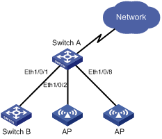
Network requirements
Switch A is an S3600 series Ethernet switch supporting PoE, Switch B can be PoE powered.
l The Ethernet 1/0/1 and Ethernet 1/0/2 ports of Switch A are connected to Switch B and an AP respectively; the Ethernet 1/0/8 port is intended to be connected with an important AP.
l The PSE processing software of Switch A is first upgraded online. The remotely accessed PDs are powered by Switch A.
l The power consumption of the accessed AP is 2,500 mW, and the maximum power consumption of Switch B is 12,000 mW.
l It is required to guarantee the power feeding to the PDs connected to the Ethernet 1/0/8 port even when Switch A is under full load.
Network diagram
Figure 1-1 Network diagram for PoE
Configuration procedure
# Upgrade the PSE processing software online.
<SwitchA> system-view
[SwitchA] poe update refresh 0290_021.s19
# Enable the PoE feature on Ethernet 1/0/1, and set the PoE maximum output power of Ethernet 1/0/1 to 12,000 mW.
[SwitchA] interface Ethernet 1/0/1
[SwitchA-Ethernet1/0/1] poe enable
[SwitchA-Ethernet1/0/1] poe max-power 12000
[SwitchA-Ethernet1/0/1] quit
# Enable the PoE feature on Ethernet 1/0/2, and set the PoE maximum output power of Ethernet 1/0/2 to 2500 mW.
[SwitchA] interface Ethernet 1/0/2
[SwitchA-Ethernet1/0/2] poe enable
[SwitchA-Ethernet1/0/2] poe max-power 2500
[SwitchA-Ethernet1/0/2] quit
# Enable the PoE feature on Ethernet 1/0/8, and set the PoE priority of Ethernet 1/0/8 to critical.
[SwitchA] interface Ethernet 1/0/8
[SwitchA-Ethernet1/0/8] poe enable
[SwitchA-Ethernet1/0/8] poe priority critical
[SwitchA-Ethernet1/0/8] quit
# Set the PoE management mode on the switch to auto (it is the default mode, so this step can be omitted).
[SwitchA] poe power-management auto
# Enable the PD compatibility detect of the switch to allow the switch to supply power to the devices noncompliant with the 802.3af standard.
[SwitchA] poe legacy enable
When configuring PoE profile, go to these sections for information you are interested in:
l Displaying PoE Profile Configuration
l PoE Profile Configuration Example
Introduction to PoE Profile
On a large-sized network or a network with mobile users, to help network administrators to monitor the PoE features of the switch, S3600 series Ethernet switches provide the PoE profile features. A PoE profile is a set of PoE configurations, including multiple PoE features.
Features of PoE profile:
l Various PoE profiles can be created. PoE policy configurations applicable to different user groups are stored in the corresponding PoE profiles. These PoE profiles can be applied to the ports used by the corresponding user groups.
l When users connect a PD to a PoE-profile-enabled port, the PoE configurations in the PoE profile will be enabled on the port.
PoE Profile Configuration
Configuring PoE Profile
Follow these steps to configure PoE profile:
|
Use the command… |
Remarks |
|||
|
Enter system view |
system-view |
— |
||
|
Create a PoE profile and enter PoE profile view |
poe-profile profilename |
Required If the PoE file is created, you will enter PoE profile view directly through the command. |
||
|
Configure the relevant features in PoE profile |
Enable the PoE feature on a port |
poe enable |
Required Disabled by default. |
|
|
Configure PoE mode for Ethernet ports |
poe mode { signal | spare } |
Optional signal by default. |
||
|
Configure the PoE priority for Ethernet ports |
poe priority { critical | high | low } |
Optional low by default. |
||
|
Configure the maximum power for Ethernet ports |
poe max-power max-power |
Optional 15,400 mW by default. |
||
|
Quit system view |
quit |
— |
||
|
Apply the existing PoE profile to the specified Ethernet port |
In system view |
apply poe-profile profile-name interface interface-type interface-number [ to interface-type interface-number ] |
Use either approach. |
|
|
In Ethernet port view |
Enter Ethernet port view |
interface interface-type interface-number |
||
|
Apply the existing PoE profile to the port |
apply poe-profile profile-name |
|||
Note the following during the configuration:
1) When the apply poe-profile command is used to apply a PoE profile to a port, some PoE features in the PoE profile can be applied successfully while some cannot. PoE profiles are applied to S3600 series Ethernet switches according to the following rules:
l When the apply poe-profile command is used to apply a PoE profile to a port, the PoE profile is applied successfully only if one PoE feature in the PoE profile is applied properly. When the display current-configuration command is used for query, it is displayed that the PoE profile is applied properly to the port.
l If one or more features in the PoE profile are not applied properly on a port, the switch will prompt explicitly which PoE features in the PoE profile are not applied properly on which ports.
l The display current-configuration command can be used to query which PoE profile is applied to a port. However, the command cannot be used to query which PoE features in a PoE profiles are applied successfully.
2) PoE profile configuration is a global configuration, and applies synchronously in the Intelligent Resilient Framework (IRF) system.
3) Combination of Unit creates a new Fabric. In the newly created Fabric, the PoE profile configuration of the Unit with the smallest Unit ID number will become the PoE profile configuration for the Fabric currently in use.
4) Split of Fabric results in many new Fabrics. In each newly created Fabric, the PoE profile configuration of each Unit remains the same as it was before the split.
Displaying PoE Profile Configuration
|
To do… |
Use the command… |
Remarks |
|
Display the detailed information about the PoE profiles created on the switch |
display poe-profile { all-profile | interface interface-type interface-number | name profile-name } |
Available in any view |
PoE Profile Configuration Example
PoE Profile Application Example
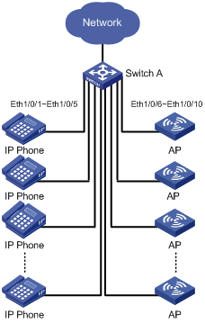
Network requirements
Switch A is an S3600 series Ethernet switch supporting PoE.
Ethernet 1/0/1 through Ethernet 1/0/10 of Switch A are used by users of group A, who have the following requirements:
l The PoE function can be enabled on all ports in use.
l Signal mode is used to supply power.
l The PoE priority for Ethernet 1/0/1 through Ethernet 1/0/5 is Critical, whereas the PoE priority for Ethernet 1/0/6 through Ethernet 1/0/10 is High.
l The maximum power for Ethernet 1/0/1 through Ethernet 1/0/5 ports is 3000 mW, whereas the maximum power for Ethernet 1/0/6 through Ethernet 1/0/10 is 15400 mW.
Based on the above requirements, two PoE profiles are made for users of group A.
l Apply PoE profile 1 for Ethernet 1/0/1 through Ethernet 1/0/5;
l Apply PoE profile 2 for Ethernet 1/0/6 through Ethernet 1/0/10.
Network diagram
Figure 2-1 PoE profile application
Configuration procedure
# Create Profile 1, and enter PoE profile view.
<SwitchA> system-view
[SwitchA] poe-profile Profile1
# In Profile 1, add the PoE policy configuration applicable to Ethernet 1/0/1 through Ethernet 1/0/5 ports for users of group A.
[SwitchA-poe-profile-Profile1] poe enable
[SwitchA-poe-profile-Profile1] poe mode signal
[SwitchA-poe-profile-Profile1] poe priority critical
[SwitchA-poe-profile-Profile1] poe max-power 3000
[SwitchA-poe-profile-Profile1] quit
# Display detailed configuration information for Profile1.
[SwitchA] display poe-profile name Profile1
Poe-profile: Profile1, 3 action
poe enable
poe max-power 3000
poe priority critical
# Create Profile 2, and enter PoE profile view.
[SwitchA] poe-profile Profile2
# In Profile 2, add the PoE policy configuration applicable to Ethernet 1/0/6 through Ethernet 1/0/10 ports for users of group A.
[SwitchA-poe-profile-Profile2] poe enable
[SwitchA-poe-profile-Profile2] poe mode signal
[SwitchA-poe-profile-Profile2] poe priority high
[SwitchA-poe-profile-Profile2] poe max-power 15400
[SwitchA-poe-profile-Profile2] quit
# Display detailed configuration information for Profile2.
[SwitchA] display poe-profile name Profile2
Poe-profile: Profile2, 2 action
poe enable
poe priority high
# Apply the configured Profile 1 to Ethernet 1/0/1 through Ethernet 1/0/5 ports.
[SwitchA] apply poe-profile Profile1 interface Ethernet1/0/1 to Ethernet1/0/5
# Apply the configured Profile 2 to Ethernet 1/0/6 through Ethernet 1/0/10 ports.
[SwitchA] apply poe-profile Profile2 interface Ethernet1/0/6 to Ethernet1/0/10