- Table of Contents
-
- H3C S3600 Operation Manual-Release 1602(V1.02)
- 00-1Cover
- 00-2Product Overview
- 01-CLI Operation
- 02-Login Operation
- 03-Configuration File Management Operation
- 04-VLAN Operation
- 05-IP Address and Performance Operation
- 06-Voice VLAN Operation
- 07-GVRP Operation
- 08-Port Basic Configuration Operation
- 09-Link Aggregation Operation
- 10-Port Isolation Operation
- 11-Port Security-Port Binding Operation
- 12-DLDP Operation
- 13-MAC Address Table Management Operation
- 14-Auto Detect Operation
- 15-MSTP Operation
- 16-Routing Protocol Operation
- 17-Multicast Operation
- 18-802.1x and System Guard Operation
- 19-AAA Operation
- 20-Web Authentication Operation
- 21-MAC Address Authentication Operation
- 22-VRRP Operation
- 23-ARP Operation
- 24-DHCP Operation
- 25-ACL Operation
- 26-QoS-QoS Profile Operation
- 27-Web Cache Redirection Operation
- 28-Mirroring Operation
- 29-IRF Fabric Operation
- 30-Cluster Operation
- 31-PoE-PoE Profile Operation
- 32-UDP Helper Operation
- 33-SNMP-RMON Operation
- 34-NTP Operation
- 35-SSH Operation
- 36-File System Management Operation
- 37-FTP-SFTP-TFTP Operation
- 38-Information Center Operation
- 39-System Maintenance and Debugging Operation
- 40-VLAN-VPN Operation
- 41-HWPing Operation
- 42-IPv6 Management Operation
- 43-DNS Operation
- 44-Smart Link-Monitor Link Operation
- 45-Access Management Operation
- 46-Appendix
- Related Documents
-
| Title | Size | Download |
|---|---|---|
| 14-Auto Detect Operation | 130.13 KB |
Introduction to the Auto Detect Function·
Auto Detect Basic Configuration
Auto Detect Implementation in Static Routing
Auto Detect Implementation in VRRP
Auto Detect Implementation in VLAN Interface Backup
Auto Detect Configuration Examples
Configuration Example for Auto Detect Implementation in Static Routing
Configuration Example for Auto Detect Implementation in VRRP
Configuration Example for Auto Detect Implementation in VLAN Interface Backup
When configuring the auto detect function, go to these sections for information you are interested in:
l Introduction to the Auto Detect Function
l Auto Detect Configuration Examples
Introduction to the Auto Detect Function
The Auto Detect function uses ICMP request/reply packets to test network connectivity regularly.
The detected object of the Auto Detect function is a detected group, which is a set of IP addresses. To check the reachability to a detected group, a switch enabled with Auto Detect sends ICMP requests to the group and waits for the ICMP replies from the group based on the user-defined policy (which includes the number of ICMP requests and the timeout waiting for a reply). Then according to the check result, the switch determines whether to make the applications using the detected group take effect.
Currently, the following features are used in conjunction with Auto Detect:
l Static route
l Virtual Router Redundancy Protocol (VRRP)
l Interface backup
![]()
l A detected group can be used by multiple applications simultaneously.
l For details about static routing, refer to the Routing Protocol part of the manual.
l For details about VRRP, refer the VRRP part of the manual.
Auto Detect Configuration
Complete the following tasks to configure auto detect:
|
Task |
Remarks |
|
Required |
|
|
Optional |
|
|
Optional |
|
|
Optional |
Auto Detect Basic Configuration
Follow these steps to configure the auto detect function:
|
Use the command… |
Remarks |
|
|
Enter system view |
system-view |
— |
|
Create a detected group and enter detected group view |
detect-group group-number |
Required |
|
Add an IP address to be detected to the detected group |
detect-list list-number ip address ip-address [ nexthop ip-address ] |
Required |
|
Specify a relationship between detected IP addresses in the group |
option [ and | or ] |
Optional By default, the and keyword is specified. |
|
Set an interval between detecting operations |
timer loop interval |
Optional By default, the detecting interval is 15 seconds. |
|
Set the number of ICMP requests during a detecting operation |
retry retry-times |
Optional By default, the number is 2. |
|
Set a timeout waiting for an ICMP reply |
timer wait seconds |
Optional By default, the timeout is 2 seconds. |
|
Display the detected group configuration |
display detect-group [ group-number ] |
Available in any view |
![]()
If the relationship between IP addresses of a detected group is and, any unreachable IP address in the group makes the detected group unreachable and the remaining IP addresses will not be detected. If the relationship is or, any reachable IP address makes the detected group reachable and the remaining IP addresses will not be detected.
Auto Detect Implementation in Static Routing
You can bind a static route with a detected group. The Auto Detect function will then detect the reachability of the static route through the path specified in the detected group.
l The static route is valid if the detected group is reachable.
l The static route is invalid if the detected group is unreachable.
![]()
You need to create the detected group before performing the following operations.
Follow these steps to configure the auto detect function for a static route:
|
To do… |
Use the command… |
Remarks |
|
Enter system view |
system-view |
— |
|
Bind a detected group to a static route |
ip route-static ip-address { mask | mask-length } { interface-type interface-number | next-hop } [ preference preference-value ] [ reject | blackhole ] detect-group group-number |
Required |
Auto Detect Implementation in VRRP
![]()
Currently, auto detect implementation in VRRP is only supported on S3600-EI series Ethernet switches.
You can enable Auto Detect on the master switch in a VRRP group, use the Auto Detect function to detect the routes from the master switch to other networks, and use the detection results (reachable/unreachable) to control the priority of the master switch, so as to realize the automatic master-backup switchover:
l The master switch keeps as Master when the detected group is reachable.
l The priority of the master switch decreases and thus becomes a Backup when the detected group is unreachable.
![]()
You need to create the detected group and perform VRRP-related configurations before the following operations.
Follow these steps to configure the auto detect function for VRRP:
|
To do… |
Use the command… |
Remarks |
|
Enter system view |
system-view |
— |
|
Enter VLAN interface view |
interface Vlan-interface vlan-id |
— |
|
Enable the auto detect function for VRRP |
vrrp vrid virtual-router-id track detect-group group-number [ reduced value-reduced ] |
Required |
Auto Detect Implementation in VLAN Interface Backup
Using Auto Detect can help realize VLAN interfaces backup. When data can be transmitted through two VLAN interfaces on the switch to the same destination, configure one of the VLAN interface as the active interface and the other as the standby interface. The standby interface is enabled automatically when the active fails, so as to ensure the data transmission. In this case, the Auto Detect function is implemented as follows:
l In normal situations (that is, when the detected group is reachable), the standby VLAN interface is down and packets are transmitted through the active VLAN interface.
l When the link between the active VLAN interface and the destination faults (that is, the detected group is unreachable), the system enables the backup VLAN interface.
l When the link between the active VLAN interface and the destination recovers (that is, the detected group becomes reachable again), the system shuts down the standby VLAN interface again.
![]()
You need to create the detected group and perform configurations concerning VLAN interfaces before the following operations.
Follow these steps to configure the auto detect function for VLAN interface backup:
|
To do… |
Use the command… |
Remarks |
|
Enter system view |
system-view |
— |
|
Enter VLAN interface view |
interface Vlan-interface vlan-id |
— |
|
Enable the auto detect function to implement VLAN interface backup |
standby detect-group group-number |
Required This operation is only needed on the secondary VLAN interface. |
Auto Detect Configuration Examples
Configuration Example for Auto Detect Implementation in Static Routing
Network requirements
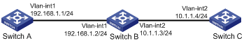
l Create detected group 8 on Switch A; detect the reachability of the IP address 10.1.1.4, with 192.168.1.2 as the next hop, and the detecting number set to 1.
l On switch A, configure a static route to Switch C.
l Enable the static route when the detected group 8 is reachable.
l To ensure normal operating of the auto detect function, configure a static route to Switch A on Switch C.
Network diagram
Figure 1-1 Network diagram for implementing the auto detect function in static route
Configuration procedure
Configure the IP addresses of all the interfaces as shown in Figure 1-1. The configuration procedure is omitted.
l Configure Switch A.
# Enter system view.
<SwitchA> system-view
# Create detected group 8.
[SwitchA] detect-group 8
# Detect the reachability of 10.1.1.4/24, with 192.168.1.2/24 as the next hop, and the detecting number set to 1.
[SwitchA-detect-group-8] detect-list 1 ip address 10.1.1.4 nexthop 192.168.1.2
[SwitchA-detect-group-8] quit
# Enable the static route when the detected group is reachable. The static route is invalid when the detected group is unreachable.
[SwitchA] ip route-static 10.1.1.4 24 192.168.1.2 detect-group 8
l Configure Switch C.
# Enter system view.
<SwitchC> system-view
# Configure a static route to Switch A.
[SwitchC] ip route-static 192.168.1.1 24 10.1.1.3
Configuration Example for Auto Detect Implementation in VRRP
Network requirements
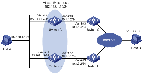
l Switch A and switch B form VRRP group 1, whose virtual IP address is 192.168.1.10.
l Packets sourced from Host A and destined for Host B is forwarded by Switch A under normal situations.
l When the connection between Switch A and Switch C fails, Switch B becomes the master in VRRP group 1 automatically and the link from Switch B to Host B, the backup link, is enabled.
Network diagram
Figure 1-2 Network diagram for implementing the auto detect function in VRRP
Configuration procedure
Configure the IP addresses of all the interfaces as shown in Figure 1-2. The configuration procedure is omitted.
l Configure Switch A.
# Create detected group 9.
<SwitchA> system-view
[SwitchA] detect-group 9
# Specify to detect the reachability of the IP address 10.1.1.4/24, setting the detect number to 1.
[SwitchA-detect-group-9] detect-list 1 ip address 10.1.1.4
[SwitchA-detect-group-9] quit
# Enable VRRP on VLAN-interface 1 and assign a virtual IP address to the VRRP group.
[SwitchA] interface vlan-interface 1
[SwitchA-Vlan-interface1] vrrp vrid 1 virtual-ip 192.168.1.10
# Set the VRRP group priority of switch A to 110, and specify to decrease the priority by 20 when the result of detected group 9 is unreachable.
[SwitchA-Vlan-interface1] vrrp vrid 1 priority 110
[SwitchA-Vlan-interface1] vrrp vrid 1 track detect-group 9 reduced 20
l Configure Switch B.
# Enable VRRP on VLAN-interface 1 and assign a virtual IP address to the VRRP group.
<SwitchB> system-view
[SwitchB] interface vlan-interface 1
[SwitchB-Vlan-interface1] vrrp vrid 1 virtual-ip 192.168.1.10
# Set the VRRP group priority of Switch B to 100.
[SwitchB-Vlan-interface1] vrrp vrid 1 priority 100
Configuration Example for Auto Detect Implementation in VLAN Interface Backup
Network requirements
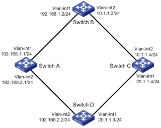
l Make sure the routes between Switch A, Switch B, and Switch C, and between Switch A, Switch D, and Switch C are reachable.
l Create detected group 10 on Switch A to detect the connectivity between Switch B and Switch C.
l Configure VLAN-interface 1 to be the active interface, which is enabled when the detected group 10 is reachable.
l Configure VLAN-interface 2 to be the standby interface, which is enabled when the detected group 10 is unreachable.
Network diagram
Figure 1-3 Network diagram for VLAN interface backup
Configuration procedure
Configure the IP addresses of all the interfaces as shown in Figure 1-3. The configuration procedure is omitted.
# Enter system view.
<SwitchA> system-view
# Create auto detected group 10.
[SwitchA] detect-group 10
# Add the IP address of 10.1.1.4 to detected group 10 to detect the reachability of the IP address, with the IP address of 192.168.1.2 as the next hop, and the detecting number set to 1.
[SwitchA-detect-group-10] detect-list 1 ip address 10.1.1.4 nexthop 192.168.1.2
[SwitchA-detect-group-10] quit
# Specify to enable VLAN-interface 2 when the result of detected group 10 is unreachable.
[SwitchA] interface vlan-interface 2
[SwitchA-Vlan-interface2] standby detect-group 10