- Table of Contents
-
- H3C S3600 Operation Manual-Release 1602(V1.02)
- 00-1Cover
- 00-2Product Overview
- 01-CLI Operation
- 02-Login Operation
- 03-Configuration File Management Operation
- 04-VLAN Operation
- 05-IP Address and Performance Operation
- 06-Voice VLAN Operation
- 07-GVRP Operation
- 08-Port Basic Configuration Operation
- 09-Link Aggregation Operation
- 10-Port Isolation Operation
- 11-Port Security-Port Binding Operation
- 12-DLDP Operation
- 13-MAC Address Table Management Operation
- 14-Auto Detect Operation
- 15-MSTP Operation
- 16-Routing Protocol Operation
- 17-Multicast Operation
- 18-802.1x and System Guard Operation
- 19-AAA Operation
- 20-Web Authentication Operation
- 21-MAC Address Authentication Operation
- 22-VRRP Operation
- 23-ARP Operation
- 24-DHCP Operation
- 25-ACL Operation
- 26-QoS-QoS Profile Operation
- 27-Web Cache Redirection Operation
- 28-Mirroring Operation
- 29-IRF Fabric Operation
- 30-Cluster Operation
- 31-PoE-PoE Profile Operation
- 32-UDP Helper Operation
- 33-SNMP-RMON Operation
- 34-NTP Operation
- 35-SSH Operation
- 36-File System Management Operation
- 37-FTP-SFTP-TFTP Operation
- 38-Information Center Operation
- 39-System Maintenance and Debugging Operation
- 40-VLAN-VPN Operation
- 41-HWPing Operation
- 42-IPv6 Management Operation
- 43-DNS Operation
- 44-Smart Link-Monitor Link Operation
- 45-Access Management Operation
- 46-Appendix
- Related Documents
-
| Title | Size | Download |
|---|---|---|
| 10-Port Isolation Operation | 64.9 KB |
Table of Contents
1 Port Isolation Configuration
Displaying and Maintaining Port Isolation Configuration
Port Isolation Configuration Example
When configuring port isolation, go to these sections for information you are interested in:
l Port Isolation Configuration
l Displaying and Maintaining Port Isolation Configuration
l Port Isolation Configuration Example
Port Isolation Overview
With the port isolation feature, you can add the ports to be controlled into an isolation group to isolate the Layer 2 and Layer 3 data between each port in the isolation group. Thus, you can construct your network in a more flexible way and improve your network security.
Currently, you can create only one isolation group on an S3600 Series Ethernet switch. The number of Ethernet ports in an isolation group is not limited.
![]()
l An isolation group only isolates the member ports in it.
l Port isolation is independent of VLAN configuration.
Port Isolation Configuration
You can perform the following operations to add an Ethernet port to an isolation group, thus isolating Layer 2 and Layer 3 data among the ports in the isolation group.
Follow these steps to configure port isolation:
|
To do … |
Use the command … |
Remarks |
|
Enter system view |
system-view |
— |
|
Enter Ethernet port view |
interface interface-type interface-number |
— |
|
Add the Ethernet port to the isolation group |
port isolate |
Required By default, an isolation group contains no port. |
![]()
l When a member port of an aggregation group joins/leaves an isolation group, the other ports in the same aggregation group will join/leave the isolation group at the same time.
l For ports that belong to an aggregation group and an isolation group simultaneously, removing a port from the aggregation group has no effect on the other ports. That is, the rest ports remain in the aggregation group and the isolation group.
l Ports that belong to an aggregation group and an isolation group simultaneously are still isolated even when you remove the aggregation group in system view.
l Adding an isolated port to an aggregation group causes all the ports in the aggregation group on the local unit to be added to the isolation group.
l S3600 series Ethernet switches support cross-device port isolation if IRF fabric is enabled.
l For S3600 series Ethernet switches belonging to the same IRF Fabric, the port isolation configuration performed on a port of a cross-device aggregation group cannot be synchronized to the other ports of the aggregation group if the ports reside on other units. That is, to add multiple ports in a cross-device aggregation group to the same isolation group, you need to perform the configuration for each of the ports individually.
Displaying and Maintaining Port Isolation Configuration
|
To do … |
Use the command … |
Remarks |
|
Display information about the Ethernet ports added to the isolation group |
display isolate port |
Available in any view |
Port Isolation Configuration Example
Network requirements
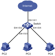
As shown in Figure 1-1, PC2, PC3 and PC4 connect to the switch ports Ethernet1/0/2, Ethernet1/0/3, and Ethernet1/0/4 respectively. The switch connects to the Internet through Ethernet1/0/1.
It is desired to isolate PC2, PC3 and PC4 to disable them from communicating directly with each other.
Network diagram
Figure 1-1 Network diagram for port isolation configuration
Configuration procedure
# Add Ethernet1/0/2, Ethernet1/0/3, and Ethernet1/0/4 to the isolation group.
<Sysname> system-view
System View: return to User View with Ctrl+Z.
[Sysname] interface ethernet1/0/2
[Sysname-Ethernet1/0/2] port isolate
[Sysname-Ethernet1/0/2] quit
[Sysname] interface ethernet1/0/3
[Sysname-Ethernet1/0/3] port isolate
[Sysname-Ethernet1/0/3] quit
[Sysname] interface ethernet1/0/4
[Sysname-Ethernet1/0/4] port isolate
[Sysname-Ethernet1/0/4] quit
[Sysname] quit
# Display information about the ports in the isolation group.
<Sysname> display isolate port
Isolated port(s) on UNIT 1:
Ethernet1/0/2, Ethernet1/0/3, Ethernet1/0/4