- Table of Contents
-
- H3C S3600 Operation Manual-Release 1602(V1.02)
- 00-1Cover
- 00-2Product Overview
- 01-CLI Operation
- 02-Login Operation
- 03-Configuration File Management Operation
- 04-VLAN Operation
- 05-IP Address and Performance Operation
- 06-Voice VLAN Operation
- 07-GVRP Operation
- 08-Port Basic Configuration Operation
- 09-Link Aggregation Operation
- 10-Port Isolation Operation
- 11-Port Security-Port Binding Operation
- 12-DLDP Operation
- 13-MAC Address Table Management Operation
- 14-Auto Detect Operation
- 15-MSTP Operation
- 16-Routing Protocol Operation
- 17-Multicast Operation
- 18-802.1x and System Guard Operation
- 19-AAA Operation
- 20-Web Authentication Operation
- 21-MAC Address Authentication Operation
- 22-VRRP Operation
- 23-ARP Operation
- 24-DHCP Operation
- 25-ACL Operation
- 26-QoS-QoS Profile Operation
- 27-Web Cache Redirection Operation
- 28-Mirroring Operation
- 29-IRF Fabric Operation
- 30-Cluster Operation
- 31-PoE-PoE Profile Operation
- 32-UDP Helper Operation
- 33-SNMP-RMON Operation
- 34-NTP Operation
- 35-SSH Operation
- 36-File System Management Operation
- 37-FTP-SFTP-TFTP Operation
- 38-Information Center Operation
- 39-System Maintenance and Debugging Operation
- 40-VLAN-VPN Operation
- 41-HWPing Operation
- 42-IPv6 Management Operation
- 43-DNS Operation
- 44-Smart Link-Monitor Link Operation
- 45-Access Management Operation
- 46-Appendix
- Related Documents
-
| Title | Size | Download |
|---|---|---|
| 15-MSTP Operation | 607.39 KB |
MSTP Implementation on Switches
Specifying the Current Switch as a Root Bridge/Secondary Root Bridge
Configuring the Bridge Priority of the Current Switch
Configuring How a Port Recognizes and Sends MSTP Packets
Configuring the MSTP Operation Mode
Configuring the Maximum Hop Count of an MST Region
Configuring the Network Diameter of the Switched Network
Configuring the MSTP Time-related Parameters
Configuring the Timeout Time Factor
Configuring the Maximum Transmitting Rate on the Current Port
Configuring the Current Port as an Edge Port
Specifying Whether the Link Connected to a Port Is Point-to-point Link
Configuring How a Port Recognizes and Sends MSTP Packets
Configuring the Timeout Time Factor
Configuring the Maximum Transmitting Rate on the Current Port
Configuring a Port as an Edge Port
Configuring the Path Cost for a Port
Specifying Whether the Link Connected to a Port Is a Point-to-point Link
Configuring TC-BPDU Attack Guard
Enabling Log/Trap Output for Ports of MSTP Instance
Enabling Trap Messages Conforming to 802.1d Standard
Displaying and Maintaining MSTP
VLAN-VPN tunnel Configuration Example
Go to these sections for information you are interested in:
l Configuring Rapid Transition
l STP Maintenance Configuration
l Enabling Trap Messages Conforming to 802.1d Standard
l Displaying and Maintaining MSTP
l VLAN-VPN tunnel Configuration Example
![]()
The following features were added:
l STP Maintainability. Refer to STP Maintenance Configuration.
l Displaying STP maintenance. Refer to Displaying and Maintaining MSTP.
l Sending trap messages conforming to 802.1d standard. Refer to Enabling Trap Messages Conforming to 802.1d Standard.
STP Overview
Functions of STP
Spanning tree protocol (STP) is a protocol conforming to IEEE 802.1d. It aims to eliminate loops on data link layer in a local area network (LAN). Devices running this protocol detect loops in the network by exchanging packets with one another and eliminate the loops detected by blocking specific ports until the network is pruned into one with tree topology. As a network with tree topology is loop-free, it prevents packets in it from being duplicated and forwarded endlessly and prevents device performance degradation.
Currently, in addition to the protocol conforming to IEEE 802.1d, STP also refers to the protocols based on IEEE 802.1d, such as RSTP, and MSTP.
Protocol packets of STP
STP uses bridge protocol data units (BPDUs), also known as configuration messages, as its protocol packets.
STP identifies the network topology by transmitting BPDUs between STP compliant network devices. BPDUs contain sufficient information for the network devices to complete the spanning tree calculation.
In STP, BPDUs come in two types:
l Configuration BPDUs, used to calculate spanning trees and maintain the spanning tree topology.
l Topology change notification (TCN) BPDUs, used to notify concerned devices of network topology changes, if any.
Basic concepts in STP
1) Root bridge
A tree network must have a root; hence the concept of root bridge has been introduced in STP.
There is one and only one root bridge in the entire network, and the root bridge can change alone with changes of the network topology. Therefore, the root bridge is not fixed.
Upon network convergence, the root bridge generates and sends out configuration BPDUs periodically. Other devices just forward the configuration BPDUs received. This mechanism ensures the topological stability.
2) Root port
3) Designated bridge and designated port
Refer to the following table for the description of designated bridge and designated port.
Table 1-1 Designated bridge and designated port
|
Classification |
Designated bridge |
Designated port |
|
For a device |
A designated bridge is a device that is directly connected to a switch and is responsible for forwarding BPDUs to this switch. |
The port through which the designated bridge forwards BPDUs to this device |
|
For a LAN |
A designated bridge is a device responsible for forwarding BPDUs to this LAN segment. |
The port through which the designated bridge forwards BPDUs to this LAN segment |
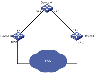
Figure 1-1 shows designated bridges and designated ports. In the figure, AP1 and AP2, BP1 and BP2, and CP1 and CP2 are ports on Device A, Device B, and Device C respectively.
l If Device A forwards BPDUs to Device B through AP1, the designated bridge for Device B is Device A, and the designated port is the port AP1 on Device A.
l Two devices are connected to the LAN: Device B and Device C. If Device B forwards BPDUs to the LAN, the designated bridge for the LAN is Device B, and the designated port is the port BP2 on Device B.
Figure 1-1 A schematic diagram of designated bridges and designated ports
![]()
All the ports on the root bridge are designated ports.
4) Path cost
Path cost is a value used for measuring link capacity. By comparing the path costs of different links, STP selects the most robust links and blocks the other links to prune the network into a tree.
How STP works
STP identifies the network topology by transmitting configuration BPDUs between network devices. Configuration BPDUs contain sufficient information for network devices to complete the spanning tree calculation. Important fields in a configuration BPDU include:
l Root bridge ID, consisting of root bridge priority and MAC address.
l Root path cost, the cost of the shortest path to the root bridge.
l Designated bridge ID, designated bridge priority plus MAC address.
l Designated port ID, designated port priority plus port name.
l Message age: lifetime for the configuration BPDUs to be propagated within the network.
l Max age, lifetime for the configuration BPDUs to be kept in a switch.
l Hello time, configuration BPDU interval.
l Forward delay, forward delay of the port.
![]()
For the convenience of description, the description and examples below involve only four parts of a configuration BPDU:
l Root bridge ID (in the form of device priority)
l Root path cost
l Designated bridge ID (in the form of device priority)
l Designated port ID (in the form of port name)
1) Detailed calculation process of the STP algorithm
l Initial state
l Selection of the optimum configuration BPDU
Each device sends out its configuration BPDU and receives configuration BPDUs from other devices.
The process of selecting the optimum configuration BPDU is as follows:
Table 1-2 Selection of the optimum configuration BPDU
|
Step |
Description |
|
1 |
Upon receiving a configuration BPDU on a port, the device performs the following processing: l If the received configuration BPDU has a lower priority than that of the configuration BPDU generated by the port, the device will discard the received configuration BPDU without doing any processing on the configuration BPDU of this port. l If the received configuration BPDU has a higher priority than that of the configuration BPDU generated by the port, the device will replace the content of the configuration BPDU generated by the port with the content of the received configuration BPDU. |
|
2 |
The device compares the configuration BPDUs of all the ports and chooses the optimum configuration BPDU. |
![]()
Principle for configuration BPDU comparison:
l The configuration BPDU that has the lowest root bridge ID has the highest priority.
l If all configuration BPDUs have the same root bridge ID, they will be compared for their root path costs. If the root path cost in a configuration BPDU plus the path cost corresponding to this port is S, the configuration BPDU with the smallest S value has the highest priority.
l If all configuration BPDUs have the same root path cost, the following configuration BPDU priority is compared sequentially: designated bridge IDs, designated port IDs, and then the IDs of the ports on which the configuration BPDUs are received. The switch with a higher priority is elected as the root bridge.
l Selection of the root bridge
At network initialization, each STP-compliant device on the network assumes itself to be the root bridge, with the root bridge ID being its own bridge ID. By exchanging configuration BPDUs, the devices compare one another’s root bridge ID. The device with the smallest root bridge ID is elected as the root bridge.
l Selection of the root port and designated ports
The process of selecting the root port and designated ports is as follows:
Table 1-3 Selection of the root port and designated ports
|
Step |
Description |
|
1 |
A non-root-bridge device takes the port on which the optimum configuration BPDU was received as the root port. |
|
2 |
Based on the configuration BPDU and the path cost of the root port, the device calculates a designated port configuration BPDU for each of the rest ports. l The root bridge ID is replaced with that of the configuration BPDU of the root port. l The root path cost is replaced with that of the configuration BPDU of the root port plus the path cost corresponding to the root port. l The designated bridge ID is replaced with the ID of this device. l The designated port ID is replaced with the ID of this port. |
|
3 |
The device compares the calculated configuration BPDU with the configuration BPDU on the port whose role is to be determined, and acts as follows based on the comparison result: l If the calculated configuration BPDU is superior, this port will serve as the designated port, and the configuration BPDU on the port will be replaced with the calculated configuration BPDU, which will be sent out periodically. l If the configuration BPDU on the port is superior, the device stops updating the configuration BPDUs of the port and blocks the port, so that the port only receives configuration BPDUs, but does not forward data or send configuration BPDUs. |
![]()
When the network topology is stable, only the root port and designated ports forward traffic, while other ports are all in the blocked state – they only receive STP packets but do not forward user traffic.
Once the root bridge, the root port on each non-root bridge and designated ports have been successfully elected, the entire tree-shaped topology has been constructed.
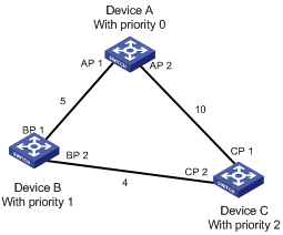
The following is an example of how the STP algorithm works. The specific network diagram is shown in Figure 1-2 The priority of Device A is 0, the priority of Device B is 1, the priority of Device C is 2, and the path costs of these links are 5, 10 and 4 respectively.
Figure 1-2 Network diagram for STP algorithm
l Initial state of each device
The following table shows the initial state of each device.
Table 1-4 Initial state of each device
|
Device |
Port name |
BPDU of port |
|
Device A |
AP1 |
{0, 0, 0, AP1} |
|
AP2 |
{0, 0, 0, AP2} |
|
|
Device B |
BP1 |
{1, 0, 1, BP1} |
|
BP2 |
{1, 0, 1, BP2} |
|
|
Device C |
CP1 |
{2, 0, 2, CP1} |
|
CP2 |
{2, 0, 2, CP2} |
l Comparison process and result on each device
The following table shows the comparison process and result on each device.
Table 1-5 Comparison process and result on each device
|
Device |
Comparison process |
BPDU of port after comparison |
|
Device A |
l Port AP1 receives the configuration BPDU of Device B {1, 0, 1, BP1}. Device A finds that the configuration BPDU of the local port {0, 0, 0, AP1} is superior to the configuration received message, and discards the received configuration BPDU. l Port AP2 receives the configuration BPDU of Device C {2, 0, 2, CP1}. Device A finds that the BPDU of the local port {0, 0, 0, AP2} is superior to the received configuration BPDU, and discards the received configuration BPDU. l Device A finds that both the root bridge and designated bridge in the configuration BPDUs of all its ports are Device A itself, so it assumes itself to be the root bridge. In this case, it does not make any change to the configuration BPDU of each port, and starts sending out configuration BPDUs periodically. |
AP1: {0, 0, 0, AP1} AP2: {0, 0, 0, AP2} |
|
Device B |
l Port BP1 receives the configuration BPDU of Device A {0, 0, 0, AP1}. Device B finds that the received configuration BPDU is superior to the configuration BPDU of the local port {1, 0,1, BP1}, and updates the configuration BPDU of BP1. l Port BP2 receives the configuration BPDU of Device C {2, 0, 2, CP2}. Device B finds that the configuration BPDU of the local port {1, 0, 1, BP2} is superior to the received configuration BPDU, and discards the received configuration BPDU. |
BP1: {0, 0, 0, AP1} BP2: {1, 0, 1, BP2} |
|
l Device B compares the configuration BPDUs of all its ports, and determines that the configuration BPDU of BP1 is the optimum configuration BPDU. Then, it uses BP1 as the root port, the configuration BPDUs of which will not be changed. l Based on the configuration BPDU of BP1 and the path cost of the root port (5), Device B calculates a designated port configuration BPDU for BP2 {0, 5, 1, BP2}. l Device B compares the calculated configuration BPDU {0, 5, 1, BP2} with the configuration BPDU of BP2. If the calculated BPDU is superior, BP2 will act as the designated port, and the configuration BPDU on this port will be replaced with the calculated configuration BPDU, which will be sent out periodically. |
Root port BP1: {0, 0, 0, AP1} Designated port BP2: {0, 5, 1, BP2} |
|
|
Device C |
l Port CP1 receives the configuration BPDU of Device A {0, 0, 0, AP2}. Device C finds that the received configuration BPDU is superior to the configuration BPDU of the local port {2, 0, 2, CP1}, and updates the configuration BPDU of CP1. l Port CP2 receives the configuration BPDU of port BP2 of Device B {1, 0, 1, BP2} before the message was updated. Device C finds that the received configuration BPDU is superior to the configuration BPDU of the local port {2, 0, 2, CP2}, and updates the configuration BPDU of CP2. |
CP1: {0, 0, 0, AP2} CP2: {1, 0, 1, BP2} |
|
By comparison: l The configuration BPDUs of CP1 is elected as the optimum configuration BPDU, so CP1 is identified as the root port, the configuration BPDUs of which will not be changed. l Device C compares the calculated designated port configuration BPDU {0, 10, 2, CP2} with the configuration BPDU of CP2, and CP2 becomes the designated port, and the configuration BPDU of this port will be replaced with the calculated configuration BPDU. |
Root port CP1: {0, 0, 0, AP2} Designated port CP2: {0, 10, 2, CP2} |
|
|
l Next, port CP2 receives the updated configuration BPDU of Device B {0, 5, 1, BP2}. Because the received configuration BPDU is superior to its old one, Device C launches a BPDU update process. l At the same time, port CP1 receives configuration BPDUs periodically from Device A. Device C does not launch an update process after comparison. |
CP1: {0, 0, 0, AP2} CP2: {0, 5, 1, BP2} |
|
|
By comparison: l Because the root path cost of CP2 (9) (root path cost of the BPDU (5) + path cost corresponding to CP2 (4)) is smaller than the root path cost of CP1 (10) (root path cost of the BPDU (0) + path cost corresponding to CP2 (10)), the BPDU of CP2 is elected as the optimum BPDU, and CP2 is elected as the root port, the messages of which will not be changed. l After comparison between the configuration BPDU of CP1 and the calculated designated port configuration BPDU, port CP1 is blocked, with the configuration BPDU of the port remaining unchanged, and the port will not receive data from Device A until a spanning tree calculation process is triggered by a new condition, for example, the link from Device B to Device C becomes down. |
Blocked port CP2: {0, 0, 0, AP2} Root port CP2: {0, 5, 1, BP2} |
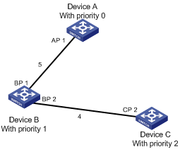
After the comparison processes described in the table above, a spanning tree with Device A as the root bridge is stabilized, as shown in Figure 1-3.
Figure 1-3 The final calculated spanning tree
![]()
To facilitate description, the spanning tree calculation process in this example is simplified, while the actual process is more complicated.
2) The BPDU forwarding mechanism in STP
l Upon network initiation, every switch regards itself as the root bridge, generates configuration BPDUs with itself as the root, and sends the configuration BPDUs at a regular interval of hello time.
l If it is the root port that received the configuration BPDU and the received configuration BPDU is superior to the configuration BPDU of the port, the device will increase message age carried in the configuration BPDU by a certain rule and start a timer to time the configuration BPDU while it sends out this configuration BPDU through the designated port.
l If the configuration BPDU received on the designated port has a lower priority than the configuration BPDU of the local port, the port will immediately sends out its better configuration BPDU in response.
l If a path becomes faulty, the root port on this path will no longer receive new configuration BPDUs and the old configuration BPDUs will be discarded due to timeout. In this case, the device generates configuration BPDUs with itself as the root bridge and sends configuration BPDUs and TCN BPDUs. This triggers a new spanning tree calculation so that a new path is established to restore the network connectivity.
However, the newly calculated configuration BPDU will not be propagated throughout the network immediately, so the old root ports and designated ports that have not detected the topology change continue forwarding data through the old path. If the new root port and designated port begin to forward data as soon as they are elected, a temporary loop may occur.
3) STP timers
The following three time parameters are important for STP calculation:
l Forward delay, the period a device waits before state transition.
A link failure triggers a new round of spanning tree calculation and results in changes of the spanning tree. However, as new configuration BPDUs cannot be propagated throughout the network immediately, if the new root port and designated port begin to forward data as soon as they are elected, loops may temporarily occur.
For this reason, the protocol uses a state transition mechanism. Namely, a newly elected root port and the designated ports must go through a period, which is twice the forward delay time, before they transit to the forwarding state. The period allows the new configuration BPDUs to be propagated throughout the entire network.
l Hello time, the interval for sending hello packets. Hello packets are used to check link state.
A switch sends hello packets to its neighboring devices at a regular interval (the hello time) to check whether the links are faulty.
l Max time, lifetime of the configuration BPDUs stored in a switch. A configuration BPDU that has “expired” is discarded by the switch.
MSTP Overview
Background of MSTP
Disadvantages of STP and RSTP
STP does not support rapid state transition of ports. A newly elected root port or designated port must wait twice the forward delay time before transiting to the forwarding state, even if it is a port on a point-to-point link or it is an edge port (an edge port refers to a port that directly connects to a user terminal rather than to another device or a shared LAN segment.)
The rapid spanning tree protocol (RSTP) is an optimized version of STP. RSTP allows a newly elected root port or designated port to enter the forwarding state much quicker under certain conditions than in STP. As a result, it takes a shorter time for the network to reach the final topology stability.
![]()
l In RSTP, the state of a root port can transit fast under the following conditions: the old root port on the device has stopped forwarding data and the upstream designated port has started forwarding data.
l In RSTP, the state of a designated port can transit fast under the following conditions: the designated port is an edge port or a port connected with a point-to-point link. If the designated port is an edge port, it can enter the forwarding state directly; if the designated port is connected with a point-to-point link, it can enter the forwarding state immediately after the device undergoes handshake with the downstream device and gets a response.
RSTP supports rapid convergence. Like STP, it is of the following disadvantages: all bridges in a LAN are on the same spanning tree; redundant links cannot be blocked by VLAN; the packets of all VLANs are forwarded along the same spanning tree.
Features of MSTP
The multiple spanning tree protocol (MSTP) overcomes the shortcomings of STP and RSTP. In addition to support for rapid network convergence, it also allows data flows of different VLANs to be forwarded along their own paths, thus providing a better load sharing mechanism for redundant links.
MSTP features the following:
l MSTP supports mapping VLANs to MST instances (MSTIs) by means of a VLAN-to-MSTI mapping table. MSTP introduces instance (integrates multiple VLANs into a set) and can bind multiple VLANs to an instance, thus saving communication overhead and improving resource utilization.
l MSTP divides a switched network into multiple regions, each containing multiple spanning trees that are independent of one another.
l MSTP prunes a ring network into a network with tree topology, preventing packets from being duplicated and forwarded in a network endlessly. Furthermore, it offers multiple redundant paths for forwarding data, and thus achieves load balancing for forwarding VLAN data.
l MSTP is compatible with STP and RSTP.
Basic MSTP Terminologies
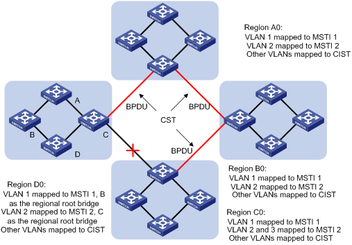
Figure 1-4 illustrates basic MSTP terms (assuming that MSTP is enabled on each switch in this figure).
Figure 1-4 Basic MSTP terminologies
MST region
A multiple spanning tree region (MST region) comprises multiple physically-interconnected MSTP-enabled switches and the corresponding network segments connected to these switches. These switches have the same region name, the same VLAN-to-MSTI mapping configuration and the same MSTP revision level.
A switched network can contain multiple MST regions. You can group multiple switches into one MST region by using the corresponding MSTP configuration commands.
As shown in Figure 1-4, all the switches in region A0 are of the same MST region-related configuration, including:
l Region name
l VLAN-to-MSTI mapping (that is, VLAN 1 is mapped to MSTI 1, VLAN 2 is mapped to MSTI 2, and the other VLANs are mapped to CIST.)
l MSTP revision level (not shown in Figure 1-4)
MSTI
A multiple spanning tree instance (MSTI) refers to a spanning tree in an MST region.
Multiple spanning trees can be established in one MST region. These spanning trees are independent of each other. For example, each region in Figure 1-4 contains multiple spanning trees known as MSTIs. Each of these spanning trees corresponds to a VLAN.
VLAN-to-MSTI mapping table
A VLAN-to-MSTI mapping table is maintained for each MST region. The table is a collection of mappings between VLANs and MSTIs. For example, in Figure 1-4, the VLAN-to-MSTI mapping table of region A0 contains these mappings: VLAN 1 to MSTI 1; VLAN 2 to MSTI 2, and other VLANs to CIST. In an MST region, load balancing is implemented according to the VLAN-to-MSTI mapping table.
IST
An internal spanning tree (IST) is a spanning tree in an MST region.
ISTs together with the common spanning tree (CST) form the common and internal spanning tree (CIST) of the entire switched network. An IST is a special MSTI; it is a branch of CIST in the MST region.
In Figure 1-4, each MST region has an IST, which is a branch of the CIST.
CST
A CST is a single spanning tree in a switched network that connects all MST regions in the network. If you regard each MST region in the network as a “switch”, then the CST is the spanning tree generated by STP or RSTP running on the "switches".
CIST
A CIST is the spanning tree in a switched network that connects all switches in the network. It comprises the ISTs and the CST.
In Figure 1-4, the ISTs in the MST regions and the CST connecting the MST regions form the CIST.
Region root
A region root is the root of the IST or an MSTI in an MST region. Different spanning trees in an MST region may have different topologies and thus have different region roots.
In region D0 shown in Figure 1-4, the region root of MSTI 1 is switch B, and the region root of MSTI 2 is switch C.
Common root bridge
The common root bridge is the root of the CIST. The common root bridge of the network shown in Figure 1-4 is a switch in region A0.
Port role
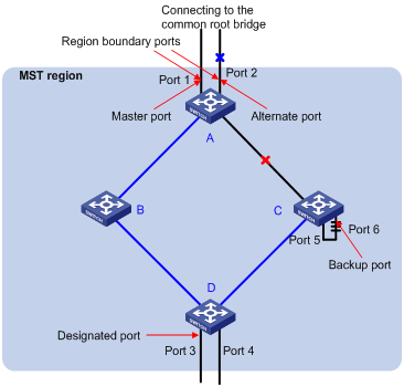
MSTP calculation involves the following port roles: root port, designated port, master port, region boundary port, alternate port, and backup port.
l A root port is used to forward packets to the root.
l A designated port is used to forward packets to a downstream network segment or switch.
l A master port connects an MST region to the common root. The path from the master port to the common root is the shortest path between the MST region and the common root. In the CST, the master port is the root port of the region, which is considered as a node. The master port is a special boundary port. It is a root port in the IST/CIST while a master port in the other MSTIs.
l A region boundary port is located on the boundary of an MST region and is used to connect one MST region to another MST region, an STP-enabled region or an RSTP-enabled region.
l An alternate port is a secondary port of a root port or master port and is used for rapid transition. With the root port or master port being blocked, the alternate port becomes the new root port or master port.
l A backup port is the secondary port of a designated port and is used for rapid transition. With the designated port being blocked, the backup port becomes the new designated port fast and begins to forward data seamlessly. When two ports of an MSTP-enabled switch are interconnected, the switch blocks one of the two ports to eliminate the loop that occurs. The blocked port is the backup port.
In Figure 1-5, switch A, switch B, switch C, and switch D form an MST region. Port 1 and port 2 on switch A connect upstream to the common root. Port 5 and port 6 on switch C form a loop. Port 3 and port 4 on switch D connect downstream to other MST regions. This figure shows the roles these ports play.
![]()
l A port can play different roles in different MSTIs.
l The role a region boundary port plays in an MSTI is consistent with the role it plays in the CIST. The master port, which is a root port in the CIST while a master port in the other MSTIs, is an exception.
l For example, in Figure 1-5, port 1 on switch A is a region boundary port. It is a root port in the CIST while a master port in all the other MSTIs in the region.
Port state
In MSTP, a port can be in one of the following three states:
l Forwarding state. Ports in this state can forward user packets and receive/send BPDU packets.
l Learning state. Ports in this state can receive/send BPDU packets but do not forward user packets.
l Discarding state. Ports in this state can only receive BPDU packets.
Port roles and port states are not mutually dependent. Table 1-6 lists possible combinations of port states and port roles.
Table 1-6 Combinations of port states and port roles
|
Port role |
Root/master port |
Designated port |
Region Boundary port |
Alternate port |
Backup port |
|
Port state |
|||||
|
Forwarding |
√ |
√ |
√ |
— |
— |
|
Learning |
√ |
√ |
√ |
— |
— |
|
Discarding |
√ |
√ |
√ |
√ |
√ |
Principle of MSTP
MSTP divides a Layer 2 network into multiple MST regions. The CSTs are generated between these MST regions, and multiple spanning trees (also called MSTIs) can be generated in each MST region. As well as RSTP, MSTP uses configuration BPDUs for spanning tree calculation. The only difference is that the configuration BPDUs for MSTP carry the MSTP configuration information on the switches.
Calculate the CIST
Through comparing configuration BPDUs, the switch of the highest priority in the network is selected as the root of the CIST. In each MST region, an IST is calculated by MSTP. At the same time, MSTP regards each MST region as a switch to calculate the CSTs of the network. The CSTs, together with the ISTs, form the CIST of the network.
Calculate an MSTI
In an MST region, different MSTIs are generated for different VLANs based on the VLAN-to-MSTI mappings. Each spanning tree is calculated independently, in the same way as how STP/RSTP is calculated.
Implement STP algorithm
In the beginning, each switch regards itself as the root, and generates a configuration BPDU for each port on it as a root, with the root path cost being 0, the ID of the designated bridge being that of the switch, and the designated port being itself.
1) Each switch sends out its configuration BPDUs and operates in the following way when receiving a configuration BPDU on one of its ports from another switch:
l If the priority of the configuration BPDU is lower than that of the configuration BPDU of the port itself, the switch discards the BPDU and does not change the configuration BPDU of the port.
l If the priority of the configuration BPDU is higher than that of the configuration BPDU of the port itself, the switch replaces the configuration BPDU of the port with the received one and compares it with those of other ports on the switch to obtain the one with the highest priority.
2) Configuration BPDUs are compared as follows:
l The smaller the root ID of the configuration BPDU is, the higher the priority of the configuration BPDU is.
l For configuration BPDUs with the same root IDs, the path costs are compared. Suppose S is the sum of the root path costs and the corresponding path cost of the port. The less the S value is, the higher the priority of the configuration BPDU is.
l For configuration BPDUs with both the same root ID and the same root path cost, the designated bridge ID, designated port ID, the ID of the receiving port are compared in turn.
3) A spanning tree is calculated as follows:
l Determining the root bridge
Root bridges are selected by configuration BPDU comparing. The switch with the smallest root ID is chosen as the root bridge.
l Determining the root port
For each switch in a network, the port on which the configuration BPDU with the highest priority is received is chosen as the root port of the switch.
l Determining the designated port
First, the switch calculates a designated port configuration BPDU for each of its ports using the root port configuration BPDU and the root port path cost, with the root ID being replaced with that of the root port configuration BPDU, root path cost being replaced with the sum of the root path cost of the root port configuration BPDU and the path cost of the root port, the ID of the designated bridge being replaced with that of the switch, and the ID of the designated port being replaced with that of the port.
The switch then compares the calculated configuration BPDU with the original configuration BPDU received from the corresponding port on another switch. If the latter takes precedence over the former, the switch blocks the local port and keeps the port's configuration BPDU unchanged, so that the port can only receive configuration messages and cannot forward packets. Otherwise, the switch sets the local port to the designated port, replaces the original configuration BPDU of the port with the calculated one and advertises it regularly.
MSTP Implementation on Switches
MSTP is compatible with both STP and RSTP. That is, MSTP-enabled switches can recognize the protocol packets of STP and RSTP and use them for spanning tree calculation. In addition to the basic MSTP functions, H3C series switches also provide the following functions for users to manage their switches.
l Root bridge hold
l Root bridge backup
l Root guard
l BPDU guard
l Loop guard
l TC-BPDU attack guard
l BPDU packet drop
STP-related Standards
STP-related standards include the following.
l IEEE 802.1D: spanning tree protocol
l IEEE 802.1w: rapid spanning tree protocol
l IEEE 802.1s: multiple spanning tree protocol
Configuring Root Bridge
Complete the following tasks to configure the root bridge:
|
Task |
Remarks |
|
Required To prevent network topology jitter caused by other related configurations, you are recommended to enable MSTP after other related configurations are performed. |
|
|
Required |
|
|
Specifying the Current Switch as a Root Bridge/Secondary Root Bridge |
Required |
|
Optional The priority of a switch cannot be changed after the switch is specified as the root bridge or a secondary root bridge. |
|
|
Optional |
|
|
Optional |
|
|
Optional |
|
|
Optional The default value is recommended. |
|
|
Optional The default values are recommended. |
|
|
Optional |
|
|
Configuring the Maximum Transmitting Rate on the Current Port |
Optional The default value is recommended. |
|
Optional |
|
|
Specifying Whether the Link Connected to a Port Is Point-to-point Link |
Optional |
![]()
In a network containing switches with both GVRP and MSTP enabled, GVRP messages travel along the CIST. If you want to advertise a VLAN through GVRP, be sure to map the VLAN to the CIST (MSTI 0) when configuring the VLAN-to-MSTI mapping table.
Configuration Prerequisites
The role (root, branch, or leaf) of each switch in each MSTI is determined.
Configuring an MST Region
Configuration procedure
Follow these steps to configure an MST region:
|
To do... |
Use the command... |
Remarks |
|
Enter system view |
system-view |
— |
|
Enter MST region view |
stp region-configuration |
— |
|
Configure the name of the MST region |
region-name name |
Required The default MST region name of a switch is its MAC address. |
|
Configure the VLAN-to-MSTI mapping table for the MST region |
instance instance-id vlan vlan-list |
Required Both commands can be used to configure VLAN-to-MSTI mapping tables. By default, all VLANs in an MST region are mapped to MSTI 0. |
|
vlan-mapping modulo modulo |
||
|
Configure the MSTP revision level for the MST region |
revision-level level |
Required The default revision level of an MST region is level 0. |
|
Activate the configuration of the MST region manually |
active region-configuration |
Required |
|
Display the configuration of the current MST region |
check region-configuration |
Optional |
|
Display the currently valid configuration of the MST region |
display stp region-configuration |
Available in any view |
![]()
NTDP packets sent by devices in a cluster can only be transmitted within the MSTI where the management VLAN of the cluster resides.
Configuring MST region-related parameters (especially the VLAN-to-MSTI mapping table) results in spanning tree recalculation and network topology jitter. To reduce network topology jitter caused by the configuration, MSTP does not recalculate spanning trees immediately after the configuration; it does this only after you perform one of the following operations, and then the configuration can really takes effect:
l Activate the new MST region-related settings by using the active region-configuration command
l Enable MSTP by using the stp enable command
![]()
l MSTP-enabled switches are in the same region only when they have the same format selector (a 802.1s-defined protocol selector, which is 0 by default and cannot be configured), MST region name, VLAN-to-MSTI mapping table, and revision level.
l The H3C series support only the MST region name, VLAN-to-MSTI mapping table, and revision level. Switches with the settings of these parameters being the same are assigned to the same MST region.
Configuration example
# Configure an MST region named info, the MSTP revision level being level 1, VLAN 2 through VLAN 10 being mapped to MSTI 1, and VLAN 20 through VLAN 30 being mapped to MSTI 2.
<Sysname> system-view
[Sysname] stp region-configuration
[Sysname-mst-region] region-name info
[Sysname-mst-region] instance 1 vlan 2 to 10
[Sysname-mst-region] instance 2 vlan 20 to 30
[Sysname-mst-region] revision-level 1
[Sysname-mst-region] active region-configuration
# Verify the above configuration.
[Sysname-mst-region] check region-configuration
Admin configuration
Format selector :0
Region name :info
Revision level :1
Instance Vlans Mapped
0 1, 11 to 19, 31 to 4094
1 2 to 10
2 20 to 30
Specifying the Current Switch as a Root Bridge/Secondary Root Bridge
Specify the current switch as the root bridge of a spanning tree
Follow these steps to specify the current switch as the root bridge of a spanning tree:
|
To do... |
Use the command... |
Remarks |
|
Enter system view |
system-view |
— |
|
Specify the current switch as the root bridge of a spanning tree |
stp [ instance instance-id ] root primary [ bridge-diameter bridgenumber [ hello-time centi-seconds ] ] |
Required |
Specify the current switch as the secondary root bridge of a spanning tree
Follow these steps to specify the current switch as the secondary root bridge of a spanning tree:
|
To do... |
Use the command... |
Remarks |
|
Enter system view |
system-view |
— |
|
Specify the current switch as the secondary root bridge of a specified spanning tree |
stp [ instance instance-id ] root secondary [ bridge-diameter bridgenumber [ hello-time centi-seconds ] ] |
Required |
Using the stp root primary/stp root secondary command, you can specify the current switch as the root bridge or the secondary root bridge of the MSTI identified by the instance-id argument. If the value of the instance-id argument is set to 0, the stp root primary/stp root secondary command specify the current switch as the root bridge or the secondary root bridge of the CIST.
A switch can play different roles in different MSTIs. That is, it can be the root bridges in an MSTI and be a secondary root bridge in another MSTI at the same time. But in the same MSTI, a switch cannot be the root bridge and the secondary root bridge simultaneously.
When the root bridge fails or is turned off, the secondary root bridge becomes the root bridge if no new root bridge is configured. If you configure multiple secondary root bridges for an MSTI, the one with the smallest MAC address replaces the root bridge when the latter fails.
You can specify the network diameter and the hello time parameters while configuring a root bridge/secondary root bridge. Refer to Configuring the Network Diameter of the Switched Network and Configuring the MSTP Time-related Parameters for information about the network diameter parameter and the hello time parameter.
![]()
l You can configure a switch as the root bridges of multiple MSTIs. But you cannot configure two or more root bridges for one MSTI. So, do not configure root bridges for the same MSTI on two or more switches using the stp root primary command.
l You can configure multiple secondary root bridges for one MSTI. That is, you can configure secondary root bridges for the same MSTI on two or more switches using the stp root secondary command.
l You can also configure the current switch as the root bridge by setting the priority of the switch to 0. Note that once a switch is configured as the root bridge or a secondary root bridge, its priority cannot be modified.
Configuration example
# Configure the current switch as the root bridge of MSTI 1 and a secondary root bridge of MSTI 2.
<Sysname> system-view
[Sysname] stp instance 1 root primary
[Sysname] stp instance 2 root secondary
Configuring the Bridge Priority of the Current Switch
Root bridges are selected according to the bridge priorities of switches. You can make a specific switch be selected as a root bridge by setting a lower bridge priority for the switch. An MSTP-enabled switch can have different bridge priorities in different MSTIs.
Configuration procedure
Follow these steps to configure the bridge priority of the current switch:
|
To do... |
Use the command... |
Remarks |
|
Enter system view |
system-view |
— |
|
Set the bridge priority for the current switch |
stp [ instance instance-id ] priority priority |
Required The default bridge priority of a switch is 32,768. |
![]()
l Once you specify a switch as the root bridge or a secondary root bridge by using the stp root primary or stp root secondary command, the bridge priority of the switch cannot be configured any more.
l During the selection of the root bridge, if multiple switches have the same bridge priority, the one with the smallest MAC address becomes the root bridge.
Configuration example
# Set the bridge priority of the current switch to 4,096 in MSTI 1.
<Sysname> system-view
[Sysname] stp instance 1 priority 4096
Configuring How a Port Recognizes and Sends MSTP Packets
A port can be configured to recognize and send MSTP packets in the following modes.
l Automatic mode. Ports in this mode determine the format of the MSTP packets to be sent according to the format of the received packets.
l Legacy mode. Ports in this mode recognize/send packets in legacy format.
l 802.1s mode. Ports in this mode recognize/send packets in dot1s format.
A port acts as follows according to the format of MSTP packets forwarded by a peer switch or router.
When a port operates in the automatic mode:
l The port automatically determines the format (legacy or dot1s) of received MSTP packets and then determines the format of the packets to be sent accordingly, thus communicating with the peer devices.
l If the format of the received packets changes repeatedly, MSTP will shut down the corresponding port to prevent network storm. A port shut down in this way can only be brought up by the network administrator.
When a port operates in the legacy mode:
l The port recognizes and sends MSTP packets in legacy format. In this case, the port can only communicate with the peer through packets in legacy format.
l If packets in dot1s format are received, the port turns to discarding state to prevent network storm.
When a port operates in the 802.1s mode:
l The port recognizes and sends MSTP packets in dot1s format. In this case, the port can only communicate with the peer through packets in dot1s format.
l If packets in legacy format are received, the port turns to discarding state to prevent network storm.
Configuration procedure
Follow these steps to configure how a port recognizes and sends MSTP packets (in system view):
|
To do... |
Use the command... |
Remarks |
|
Enter system view |
system-view |
— |
|
Configure how a port recognizes and sends MSTP packets |
stp interface interface-type interface-number compliance { auto | dot1s | legacy } |
Required By default, a port recognizes and sends MSTP packets in the automatic mode. That is, it determines the format of packets to be sent according to the format of the packets received. |
Follow these steps to configure how a port recognizes and sends MSTP packets (in Ethernet port view):
|
To do... |
Use the command... |
Remarks |
|
Enter system view |
system-view |
— |
|
Enter Ethernet port view |
interface interface-type interface-number |
— |
|
Configure how a port recognizes and sends MSTP packets |
stp compliance { auto | dot1s | legacy } |
Required By default, a port recognizes and sends MSTP packets in the automatic mode. That is, it determines the format of packets to be sent according to the format of the packets received. |
Configuration example
# Configure Ethernet 1/0/1 to recognize and send packets in dot1s format.
<Sysname> system-view
[Sysname] interface Ethernet 1/0/1
[Sysname-Ethernet1/0/1] stp compliance dot1s
# Restore the default mode for Ethernet 1/0/1 to recognize/send MSTP packets.
[Sysname-Ethernet1/0/1] undo stp compliance
Configuring the MSTP Operation Mode
l STP-compatible mode, where the ports of a switch send STP BPDUs to neighboring devices. If STP-enabled switches exist in a switched network, you can use the stp mode stp command to configure an MSTP-enabled switch to operate in STP-compatible mode.
l RSTP-compatible mode, where the ports of a switch send RSTP BPDUs to neighboring devices. If RSTP-enabled switches exist in a switched network, you can use the stp mode rstp command to configure an MSTP-enabled switch to operate in RSTP-compatible mode.
l MSTP mode, where the ports of a switch send MSTP BPDUs or STP BPDUs (if the switch is connected to STP-enabled switches) to neighboring devices. In this case, the switch is MSTP-capable.
Configuration procedure
Follow these steps to configure the MSTP operation mode:
|
To do... |
Use the command... |
Remarks |
|
Enter system view |
system-view |
— |
|
Configure the MSTP operation mode |
stp mode { stp | rstp | mstp } |
Required An MSTP-enabled switch operates in the MSTP mode by default. |
Configuration example
# Specify the MSTP operation mode as STP-compatible.
[Sysname] stp mode stp
Configuring the Maximum Hop Count of an MST Region
The maximum hop count configured on the region root is also the maximum hops of the MST region. The value of the maximum hop count limits the size of the MST region.
A configuration BPDU contains a field that maintains the remaining hops of the configuration BPDU. And a switch discards the configuration BPDUs whose remaining hops are 0. After a configuration BPDU reaches a root bridge of a spanning tree in an MST region, the value of the remaining hops field in the configuration BPDU is decreased by 1 every time the configuration BPDU passes one switch. Such a mechanism disables the switches that are beyond the maximum hop count from participating in spanning tree calculation, and thus limits the size of an MST region.
With such a mechanism, the maximum hop count configured on the switch operating as the root bridge of the CIST or an MSTI in an MST region becomes the network diameter of the spanning tree, which limits the size of the spanning tree in the current MST region. The switches that are not root bridges in the MST region adopt the maximum hop settings of their root bridges.
Configuration procedure
Follow these steps to configure the maximum hop count for an MST region:
|
To do... |
Use the command... |
Remarks |
|
Enter system view |
system-view |
— |
|
Configure the maximum hop count of the MST region |
stp max-hops hops |
Required By default, the maximum hop count of an MST region is 20. |
The bigger the maximum hop count, the larger the MST region is. Note that only the maximum hop settings on the switch operating as a region root can limit the size of the MST region.
Configuration example
# Configure the maximum hop count of the MST region to be 30.
<Sysname> system-view
[Sysname] stp max-hops 30
Configuring the Network Diameter of the Switched Network
In a switched network, any two switches can communicate with each other through a specific path made up of multiple switches. The network diameter of a network is measured by the number of switches; it equals the number of the switches on the longest path (that is, the path containing the maximum number of switches).
Configuration procedure
Follow these steps to configure the network diameter of the switched network:
|
To do... |
Use the command... |
Remarks |
|
Enter system view |
system-view |
— |
|
Configure the network diameter of the switched network |
stp bridge-diameter bridgenumber |
Required The default network diameter of a network is 7. |
The network diameter parameter indicates the size of a network. The bigger the network diameter is, the larger the network size is.
After you configure the network diameter of a switched network, an MSTP-enabled switch adjusts its hello time, forward delay, and max age settings accordingly to better values.
The network diameter setting only applies to CIST; it is invalid for MSTIs.
Configuration example
# Configure the network diameter of the switched network to 6.
<Sysname> system-view
[Sysname] stp bridge-diameter 6
Configuring the MSTP Time-related Parameters
Three MSTP time-related parameters exist: forward delay, hello time, and max age. You can configure the three parameters to control the process of spanning tree calculation.
Configuration procedure
Follow these steps to configure MSTP time-related parameters:
|
To do... |
Use the command... |
Remarks |
|
Enter system view |
system-view |
— |
|
Configure the forward delay parameter |
stp timer forward-delay centiseconds |
Required The forward delay parameter defaults to 1,500 centiseconds (namely, 15 seconds). |
|
Configure the hello time parameter |
stp timer hello centiseconds |
Required The hello time parameter defaults to 200 centiseconds (namely, 2 seconds). |
|
Configure the max age parameter |
stp timer max-age centiseconds |
Required The max age parameter defaults to 2,000 centiseconds (namely, 20 seconds). |
All switches in a switched network adopt the three time-related parameters configured on the CIST root bridge.
![]()
l The forward delay parameter and the network diameter are correlated. Normally, a large network diameter corresponds to a large forward delay. A too small forward delay parameter may result in temporary redundant paths. And a too large forward delay parameter may cause a network unable to resume the normal state in time after changes occurred to the network. The default value is recommended.
l An adequate hello time parameter enables a switch to detect link failures in time without occupying too many network resources. And a too small hello time parameter may result in duplicated configuration BPDUs being sent frequently, which increases the work load of the switches and wastes network resources. The default value is recommended.
l As for the max age parameter, if it is too small, network congestion may be falsely regarded as link failures, which results in frequent spanning tree recalculation. If it is too large, link problems may be unable to be detected in time, which prevents spanning trees being recalculated in time and makes the network less adaptive. The default value is recommended.
As for the configuration of the three time-related parameters (that is, the hello time, forward delay, and max age parameters), the following formulas must be met to prevent frequent network jitter.
2 x (forward delay – 1 second) >= max age
Max age >= 2 x (hello time + 1 second)
You are recommended to specify the network diameter of the switched network and the hello time by using the stp root primary or stp root secondary command. After that, the three proper time-related parameters are determined automatically.
Configuration example
# Configure the forward delay parameter to be 1,600 centiseconds, the hello time parameter to be 300 centiseconds, and the max age parameter to be 2,100 centiseconds (assuming that the current switch operates as the CIST root bridge).
[Sysname] stp timer forward-delay 1600
[Sysname] stp timer hello 300
[Sysname] stp timer max-age 2100
Configuring the Timeout Time Factor
When the network topology is stable, a non-root-bridge switch regularly forwards BPDUs received from the root bridge to its neighboring devices at the interval specified by the hello time parameter to check for link failures. Normally, a switch regards its upstream switch faulty if the former does not receive any BPDU from the latter in a period three times of the hello time and then initiates the spanning tree recalculation process.
Spanning trees may be recalculated even in a steady network if an upstream switch continues to be busy. You can configure the timeout time factor to a larger number to avoid such cases. Normally, the timeout time can be four or more times of the hello time. For a steady network, the timeout time can be five to seven times of the hello time.
Configuration procedure
Follow these steps to configure the timeout time factor:
|
To do... |
Use the command... |
Remarks |
|
Enter system view |
system-view |
— |
|
Configure the timeout time factor for the switch |
stp timer-factor number |
Required The timeout time factor defaults to 3. |
For a steady network, the timeout time can be five to seven times of the hello time.
Configuration example
# Configure the timeout time factor to be 6.
<Sysname> system-view
[Sysname] stp timer-factor 6
Configuring the Maximum Transmitting Rate on the Current Port
The maximum transmitting rate of a port specifies the maximum number of configuration BPDUs a port can transmit in a period specified by the hello time parameter. It depends on the physical state of the port and network structure. You can configure this parameter according to the network.
Configure the maximum transmitting rate for specified ports in system view
Follow these steps to configure the maximum transmitting rate for specified ports in system view:
|
To do... |
Use the command... |
Remarks |
|
Enter system view |
system-view |
— |
|
Configure the maximum transmitting rate for specified ports |
stp interface interface-list transmit-limit packetnum |
Required The maximum transmitting rate of all Ethernet ports on a switch defaults to 10. |
Configure the maximum transmitting rate in Ethernet port view
Follow these steps to configure the maximum transmitting rate in Ethernet port view:
|
To do... |
Use the command... |
Remarks |
|
Enter system view |
system-view |
— |
|
Enter Ethernet port view |
interface interface-type interface-number |
— |
|
Configure the maximum transmitting rate |
stp transmit-limit packetnum |
Required The maximum transmitting rate of all Ethernet ports on a switch defaults to 10. |
As the maximum transmitting rate parameter determines the number of the configuration BPDUs transmitted in each hello time, set it to a proper value to prevent MSTP from occupying too many network resources. The default value is recommended.
Configuration example
# Set the maximum transmitting rate of Ethernet 1/0/1 to 15.
1) Configure the maximum transmitting rate in system view
<Sysname> system-view
[Sysname] stp interface Ethernet 1/0/1 transmit-limit 15
2) Configure the maximum transmitting rate in Ethernet port view
<Sysname> system-view
[Sysname] interface Ethernet 1/0/1
[Sysname-Ethernet1/0/1] stp transmit-limit 15
Configuring the Current Port as an Edge Port
Edge ports are ports that neither directly connects to other switches nor indirectly connects to other switches through network segments. After a port is configured as an edge port, the rapid transition mechanism is applicable to the port. That is, when the port changes from the blocking state to the forwarding state, it does not have to wait for a delay.
You can configure a port as an edge port in one of the following two ways.
Configure a port as an edge port in system view
Follow these steps to configure a port as an edge port in system view:
|
To do... |
Use the command... |
Remarks |
|
Enter system view |
system-view |
— |
|
Configure the specified ports as edge ports |
stp interface interface-list edged-port enable |
Required By default, all the Ethernet ports of a switch are non-edge ports. |
Configure a port as an edge port in Ethernet port view
Follow these steps to configure a port as an edge port in Ethernet port view:
|
To do... |
Use the command... |
Remarks |
|
Enter system view |
system-view |
— |
|
Enter Ethernet port view |
interface interface-type interface-number |
— |
|
Configure the port as an edge port |
stp edged-port enable |
Required By default, all the Ethernet ports of a switch are non-edge ports. |
On a switch with BPDU guard disabled, an edge port becomes a non-edge port again once it receives a BPDU from another port.
![]()
You are recommended to configure the Ethernet ports connected directly to terminals as edge ports and enable the BPDU guard function at the same time. This not only enables these ports to turn to the forwarding state rapidly but also secures your network.
Configuration example
# Configure Ethernet 1/0/1 as an edge port.
1) Configure Ethernet 1/0/1 as an edge port in system view
<Sysname> system-view
[Sysname] stp interface Ethernet 1/0/1 edged-port enable
2) Configure Ethernet 1/0/1 as an edge port in Ethernet port view
[Sysname] interface Ethernet 1/0/1
[Sysname-Ethernet1/0/1] stp edged-port enable
Specifying Whether the Link Connected to a Port Is Point-to-point Link
You can determine whether or not the link connected to a port is a point-to-point link in one of the following two ways.
Specify whether the link connected to a port is point-to-point link in system view
|
To do... |
Use the command... |
Remarks |
|
Enter system view |
system-view |
— |
|
Specify whether the link connected to a port is point-to-point link |
stp interface interface-list point-to-point { force-true | force-false | auto } |
Required The auto keyword is adopted by default. |
Specify whether the link connected to a port is point-to-point link in Ethernet port view
|
To do... |
Use the command... |
Remarks |
|
Enter system view |
system-view |
— |
|
Enter Ethernet port view |
interface interface-type interface-number |
— |
|
Specify whether the link connected to a port is a point-to-point link |
stp point-to-point { force-true | force-false | auto } |
Required The auto keyword is adopted by default. |
![]()
l If you configure the link connected to a port in an aggregation group as a point-to-point link, the configuration will be synchronized to the rest ports in the same aggregation group.
l If an auto-negotiating port operates in full duplex mode after negotiation, you can configure the link of the port as a point-to-point link.
After you configure the link of a port as a point-to-point link, the configuration applies to all the MSTIs the port belongs to. If the actual physical link of a port is not a point-to-point link and you forcibly configure the link as a point-to-point link, loops may occur temporarily.
Configuration example
# Configure the link connected to Ethernet 1/0/1 as a point-to-point link.
1) Perform this configuration in system view
<Sysname> system-view
[Sysname] stp interface Ethernet 1/0/1 point-to-point force-true
2) Perform this configuration in Ethernet port view
[Sysname] interface Ethernet 1/0/1
[Sysname-Ethernet1/0/1] stp point-to-point force-true
Enabling MSTP
Configuration procedure
Follow these steps to enable MSTP in system view:
|
To do... |
Use the command... |
Remarks |
|
Enter system view |
system-view |
— |
|
Enable MSTP |
stp enable |
Required MSTP is disabled by default. |
|
Disable MSTP on specified ports |
stp interface interface-list disable |
Optional By default, MSTP is enabled on all ports after you enable MSTP in system view. To enable a switch to operate more flexibly, you can disable MSTP on specific ports. As MSTP-disabled ports do not participate in spanning tree calculation, this operation saves CPU resources of the switch. |
Follow these steps to enable MSTP in Ethernet port view:
|
To do... |
Use the command... |
Remarks |
|
Enter system view |
system-view |
— |
|
Enable MSTP |
stp enable |
Required MSTP is disabled by default. |
|
Enter Ethernet port view |
interface interface-type interface-number |
— |
|
Disable MSTP on the port |
stp disable |
Optional By default, MSTP is enabled on all ports after you enable MSTP in system view. To enable a switch to operate more flexibly, you can disable MSTP on specific ports. As MSTP-disabled ports do not participate in spanning tree calculation, this operation saves CPU resources of the switch. |
Other MSTP-related settings can take effect only after MSTP is enabled on the switch.
Configuration example
# Enable MSTP on the switch and disable MSTP on Ethernet 1/0/1.
1) Perform this configuration in system view
<Sysname> system-view
[Sysname] stp enable
[Sysname] stp interface Ethernet 1/0/1 disable
2) Perform this configuration in Ethernet port view
[Sysname] stp enable
[Sysname] interface Ethernet 1/0/1
[Sysname-Ethernet1/0/1] stp disable
Configuring Leaf Nodes
Complete the following tasks to configure leaf nodes:
|
Task |
Remarks |
|
Required To prevent network topology jitter caused by other related configurations, you are recommended to enable MSTP after performing other configurations. |
|
|
Required |
|
|
Optional |
|
|
Optional |
|
|
Configuring the Maximum Transmitting Rate on the Current Port |
Optional The default value is recommended. |
|
Optional |
|
|
Optional |
|
|
Optional |
|
|
Specifying Whether the Link Connected to a Port Is Point-to-point Link |
Optional |
![]()
In a network containing switches with both GVRP and MSTP enabled, GVRP messages travel along the CIST. If you want to advertise a VLAN through GVRP, be sure to map the VLAN to the CIST (MSTI 0) when configuring the VLAN-to-MSTI mapping table.
Configuration Prerequisites
The role (root, branch, or leaf) of each switch in each MSTI is determined.
Configuring the MST Region
Refer to Configuring an MST Region.
Configuring How a Port Recognizes and Sends MSTP Packets
Refer to Configuring How a Port Recognizes and Sends MSTP Packets.
Configuring the Timeout Time Factor
Refer to Configuring the Timeout Time Factor.
Configuring the Maximum Transmitting Rate on the Current Port
Refer to Configuring the Maximum Transmitting Rate on the Current Port.
Configuring a Port as an Edge Port
Refer to Configuring the Current Port as an Edge Port.
Configuring the Path Cost for a Port
The path cost parameter reflects the rate of the link connected to the port. For a port on an MSTP-enabled switch, the path cost may be different in different MSTIs. You can enable flows of different VLANs to travel along different physical links by configuring appropriate path costs on ports, so that VLAN-based load balancing can be implemented.
Path cost of a port can be determined by the switch or through manual configuration.
Standards for calculating path costs of ports
Currently, a switch can calculate the path costs of ports based on one of the following standards:
l dot1d-1998: Adopts the IEEE 802.1D-1998 standard to calculate the default path costs of ports.
l dot1t: Adopts the IEEE 802.1t standard to calculate the default path costs of ports.
l legacy: Adopts the proprietary standard to calculate the default path costs of ports.
Follow these steps to specify the standard for calculating path costs:
|
To do... |
Use the command... |
Remarks |
|
Enter system view |
system-view |
— |
|
Specify the standard for calculating the default path costs of the links connected to the ports of the switch |
stp pathcost-standard { dot1d-1998 | dot1t | legacy } |
Optional By default, the legacy standard is used to calculate the default path costs of ports. |
Table 1-7 Transmission rates vs. path costs
|
Rate |
Operation mode (half-/full-duplex) |
802.1D-1998 |
IEEE 802.1t |
Latency standard |
|
0 |
— |
65,535 |
200,000,000 |
200,000 |
|
10 Mbps |
Half-duplex/Full-duplex Aggregated link 2 ports Aggregated link 3 ports Aggregated link 4 ports |
100 95 95 95 |
2,000,000 1,000,000 666,666 500,000 |
2,000 1,800 1,600 1,400 |
|
100 Mbps |
Half-duplex/Full-duplex Aggregated link 2 ports Aggregated link 3 ports Aggregated link 4 ports |
19 15 15 15 |
200,000 100,000 66,666 50,000 |
200 180 160 140 |
|
1,000 Mbps |
Full-duplex Aggregated link 2 ports Aggregated link 3 ports Aggregated link 4 ports |
4 3 3 3 |
20,000 10,000 6,666 5,000 |
20 18 16 14 |
|
10 Gbps |
Full-duplex Aggregated link 2 ports Aggregated link 3 ports Aggregated link 4 ports |
2 1 1 1 |
2,000 1,000 666 500 |
2 1 1 1 |
Normally, the path cost of a port operating in full-duplex mode is slightly less than that of the port operating in half-duplex mode.
When calculating the path cost of an aggregated link, the 802.1D-1998 standard does not take the number of the ports on the aggregated link into account, whereas the 802.1T standard does. The following formula is used to calculate the path cost of an aggregated link:
Path cost = 200,000,000 / link transmission rate
Where, “link transmission rate” is the sum of the rates of all the unblocked ports on the aggregated link measured in 100 Kbps.
Configure the path cost for specific ports
Follow these steps to configure the path cost for specified ports in system view:
|
To do... |
Use the command... |
Remarks |
|
Enter system view |
System-view |
— |
|
Configure the path cost for specified ports |
stp interface interface-list [ instance instance-id ] cost cost |
Required An MSTP-enabled switch can calculate path costs for all its ports automatically. |
Follow these steps to configure the path cost for a port in Ethernet port view:
|
To do... |
Use the command... |
Remarks |
|
Enter system view |
System-view |
— |
|
Enter Ethernet port view |
interface interface-type interface-number |
— |
|
Configure the path cost for the port |
stp [ instance instance-id ] cost cost |
Required An MSTP-enabled switch can calculate path costs for all its ports automatically. |
Changing the path cost of a port may change the role of the port and put it in state transition. Executing the stp cost command with the instance-id argument being 0 sets the path cost on the CIST for the port.
Configuration example (A)
# Configure the path cost of Ethernet 1/0/1 in MSTI 1 to be 2,000.
1) Perform this configuration in system view
<Sysname> system-view
[Sysname] stp interface Ethernet 1/0/1 instance 1 cost 2000
2) Perform this configuration in Ethernet port view
<Sysname> system-view
[Sysname] interface Ethernet 1/0/1
[Sysname-Ethernet1/0/1] stp instance 1 cost 2000
Configuration example (B)
# Configure the path cost of Ethernet 1/0/1 in MSTI 1 to be calculated by the MSTP-enabled switch according to the IEEE 802.1D-1998 standard.
1) Perform this configuration in system view
<Sysname> system-view
[Sysname] undo stp interface Ethernet 1/0/1 instance 1 cost
[Sysname] stp pathcost-standard dot1d-1998
2) Perform this configuration in Ethernet port view
[Sysname] interface Ethernet 1/0/1
[Sysname-Ethernet1/0/1] undo stp instance 1 cost
[Sysname-Ethernet1/0/1] quit
[Sysname] stp pathcost-standard dot1d-1998
Configuring Port Priority
Port priority is an important criterion on determining the root port. In the same condition, the port with the smallest port priority value becomes the root port.
A port on an MSTP-enabled switch can have different port priorities and play different roles in different MSTIs. This enables packets of different VLANs to be forwarded along different physical paths, so that VLAN-based load balancing can be implemented.
You can configure port priority in one of the following two ways.
Configure port priority in system view
Follow these steps to configure port priority in system view:
|
To do... |
Use the command... |
Remarks |
|
Enter system view |
system-view |
— |
|
Configure port priority for specified ports |
stp interface interface-list instance instance-id port priority priority |
Required The default port priority is 128. |
Configure port priority in Ethernet port view
Follow these steps to configure port priority in Ethernet port view:
|
To do... |
Use the command... |
Remarks |
|
Enter system view |
system-view |
— |
|
Enter Ethernet port view |
interface interface-type interface-number |
— |
|
Configure port priority for the port |
stp [ instance instance-id ] port priority priority |
Required. The default port priority is 128. |
Changing port priority of a port may change the role of the port and put the port into state transition.
A smaller port priority value indicates a higher possibility for the port to become the root port. If all the ports of a switch have the same port priority value, the port priorities are determined by the port indexes. Changing the priority of a port will cause spanning tree recalculation.
You can configure port priorities according to actual networking requirements.
Configuration example
# Configure the port priority of Ethernet 1/0/1 in MSTI 1 to be 16.
1) Perform this configuration in system view
<Sysname> system-view
[Sysname] stp interface Ethernet 1/0/1 instance 1 port priority 16
2) Perform this configuration in Ethernet port view
[Sysname] interface Ethernet 1/0/1
[Sysname-Ethernet1/0/1] stp instance 1 port priority 16
Specifying Whether the Link Connected to a Port Is a Point-to-point Link
Refer to Specifying Whether the Link Connected to a Port Is Point-to-point Link.
Enabling MSTP
Refer to Enabling MSTP.
Performing mCheck Operation
Ports on an MSTP-enabled switch can operate in three modes: STP-compatible, RSTP-compatible, and MSTP.
A port on an MSTP-enabled switch operating as an upstream switch transits to the STP-compatible mode when it has an STP-enabled switch connected to it. When the STP-enabled downstream switch is then replaced by an MSTP-enabled switch, the port cannot automatically transit to the MSTP mode. It remains in the STP-compatible mode. In this case, you can force the port to transit to the MSTP mode by performing the mCheck operation on the port.
Configuration Prerequisites
MSTP runs normally on the switch.
Configuration Procedure
You can perform the mCheck operation in the following two ways.
Perform the mCheck operation in system view
Follow these steps to perform the mCheck operation in system view:
|
To do... |
Use the command... |
Remarks |
|
Enter system view |
system-view |
— |
|
Perform the mCheck operation |
stp [ interface interface-list ] mcheck |
Required |
Perform the mCheck operation in Ethernet port view
Follow these steps to perform the mCheck operation in Ethernet port view:
|
To do... |
Use the command... |
Remarks |
|
Enter system view |
system-view |
— |
|
Enter Ethernet port view |
interface interface-type interface-number |
— |
|
Perform the mCheck operation |
stp mcheck |
Required |
Configuration Example
# Perform the mCheck operation on Ethernet 1/0/1.
1) Perform this configuration in system view
<Sysname> system-view
[Sysname] stp interface Ethernet 1/0/1 mcheck
2) Perform this configuration in Ethernet port view
[Sysname] interface Ethernet 1/0/1
[Sysname-Ethernet1/0/1] stp mcheck
Configuring Guard Functions
Introduction
The following guard functions are available on an MSTP-enabled switch: BPDU guard, root guard, loop guard, TC-BPDU attack guard, and BPDU drop.
BPDU guard
Normally, the access ports of the devices operating on the access layer are directly connected to terminals (such as PCs) or file servers. These ports are usually configured as edge ports to achieve rapid transition. But they resume non-edge ports automatically upon receiving configuration BPDUs, which causes spanning tree recalculation and network topology jitter.
Normally, no configuration BPDU will reach edge ports. But malicious users can attack a network by sending configuration BPDUs deliberately to edge ports to cause network jitter. You can prevent this type of attacks by utilizing the BPDU guard function. With this function enabled on a switch, the switch shuts down the edge ports that receive configuration BPDUs and then reports these cases to the administrator. Ports shut down in this way can only be restored by the administrator.
Root guard
A root bridge and its secondary root bridges must reside in the same region. The root bridge of the CIST and its secondary root bridges are usually located in the high-bandwidth core region. Configuration errors or attacks may result in configuration BPDUs with their priorities higher than that of a root bridge, which causes a new root bridge to be elected and network topology jitter to occur. In this case, flows that should travel along high-speed links may be led to low-speed links, and network congestion may occur.
You can avoid this problem by utilizing the root guard function. Ports with this function enabled can only be kept as designated ports in all MSTIs. When a port of this type receives configuration BPDUs with higher priorities, it turns to the discarding state (rather than become a non-designated port) and stops forwarding packets (as if it is disconnected from the link). It resumes the normal state if it does not receive any configuration BPDUs with higher priorities for a specified period.
Loop guard
A switch maintains the states of the root port and other blocked ports by receiving and processing BPDUs from the upstream switch. These BPDUs may get lost because of network congestions or unidirectional link failures. If a switch does not receive BPDUs from the upstream switch for certain period, the switch selects a new root port; the original root port becomes a designated port; and the blocked ports turns to the forwarding state. This may cause loops in the network.
The loop guard function suppresses loops. With this function enabled, if link congestions or unidirectional link failures occur, both the root port and the blocked ports become designated ports and turn to the discarding state. In this case, they stop forwarding packets, and thereby loops can be prevented.
![]()
With the loop guard function enabled, the root guard function and the edge port configuration are mutually exclusive.
TC-BPDU attack guard
Normally, a switch removes its MAC address table and ARP entries upon receiving TC-BPDUs. If a malicious user sends a large amount of TC-BPDUs to a switch in a short period, the switch may be busy in removing the MAC address table and ARP entries, which may affect spanning tree calculation, occupy large amount of bandwidth and increase switch CPU utilization.
With the TC-BPDU attack guard function enabled, a switch performs a removing operation upon receiving a TC-BPDU and triggers a timer (set to 10 seconds by default) at the same time. Before the timer expires, the switch only performs the removing operation for limited times (up to six times by default) regardless of the number of the TC-BPDUs it receives. Such a mechanism prevents a switch from being busy in removing the MAC address table and ARP entries.
You can use the stp tc-protection threshold command to set the maximum times for a switch to remove the MAC address table and ARP entries in a specific period. When the number of the TC-BPDUs received within a period is less than the maximum times, the switch performs a removing operation upon receiving a TC-BPDU. After the number of the TC-BPDUs received reaches the maximum times, the switch stops performing the removing operation. For example, if you set the maximum times for a switch to remove the MAC address table and ARP entries to 100 and the switch receives 200 TC-BPDUs in the period, the switch removes the MAC address table and ARP entries for only 100 times within the period.
BPDU dropping
In a STP-enabled network, some users may send BPDU packets to the switch continuously in order to destroy the network. When a switch receives the BPDU packets, it will forward them to other switches. As a result, STP calculation is performed repeatedly, which may occupy too much CPU of the switches or cause errors in the protocol state of the BPDU packets.
In order to avoid this problem, you can enable BPDU dropping on Ethernet ports. Once the function is enabled on a port, the port will not receive or forward any BPDU packets. In this way, the switch is protected against the BPDU packet attacks so that the STP calculation is assured to be right.
Configuration Prerequisites
MSTP runs normally on the switch.
Configuring BPDU Guard
Configuration procedure
Follow these steps to configure BPDU guard:
|
To do... |
Use the command... |
Remarks |
|
Enter system view |
system-view |
— |
|
Enable the BPDU guard function |
stp bpdu-protection |
Required The BPDU guard function is disabled by default. |
Configuration example
# Enable the BPDU guard function.
<Sysname> system-view
[Sysname] stp bpdu-protection
![]()
As Gigabit ports of an S3600 Ethernet switch cannot be shut down, the BPDU guard function is not applicable to these ports even if you enable the BPDU guard function and specify these ports to be MSTP edge ports.
Configuring Root Guard
Configuration procedure
Follow these steps to configure the root guard function in system view:
|
To do... |
Use the command... |
Remarks |
|
Enter system view |
system-view |
— |
|
Enable the root guard function on specified ports |
stp interface interface-list root-protection |
Required The root guard function is disabled by default. |
Follow these steps to enable the root guard function in Ethernet port view:
|
To do... |
Use the command... |
Remarks |
|
Enter system view |
system-view |
— |
|
Enter Ethernet port view |
Interface interface-type interface-number |
— |
|
Enable the root guard function on the current port |
stp root-protection |
Required The root guard function is disabled by default. |
Configuration example
# Enable the root guard function on Ethernet 1/0/1.
1) Perform this configuration in system view
<Sysname> system-view
[Sysname] stp interface Ethernet 1/0/1 root-protection
2) Perform this configuration in Ethernet port view
[Sysname] interface Ethernet 1/0/1
[Sysname-Ethernet1/0/1] stp root-protection
Configuring Loop Guard
Configuration procedure
Follow these steps to configure loop guard:
|
To do... |
Use the command... |
Remarks |
|
Enter system view |
system-view |
— |
|
Enter Ethernet port view |
interface interface-type interface-number |
— |
|
Enable the loop guard function on the current port |
stp loop-protection |
Required The loop guard function is disabled by default. |
Configuration example
# Enable the loop guard function on Ethernet 1/0/1.
[Sysname] interface Ethernet 1/0/1
[Sysname-Ethernet1/0/1] stp loop-protection
Configuring TC-BPDU Attack Guard
Configuration prerequisites
MSTP runs normally on the switch.
Configuration procedure
Follow these steps to configure the TC-BPDU attack guard function:
|
To do... |
Use the command... |
Remarks |
|
Enter system view |
system-view |
— |
|
Enable the TC-BPDU attack guard function |
stp tc-protection enable |
Required The TC-BPDU attack guard function is disabled by default. |
|
Set the maximum times that a switch can remove the MAC address table and ARP entries within each 10 seconds |
stp tc-protection threshold number |
Optional |
Configuration example
# Enable the TC-BPDU attack guard function
[Sysname] stp tc-protection enable
# Set the maximum times for the switch to remove the MAC address table and ARP entries within 10 seconds to 5.
<Sysname> system-view
[Sysname] stp tc-protection threshold 5
Configuring BPDU Dropping
Follow these steps to configure BPDU dropping:
|
To do... |
Use the command... |
Remarks |
|
Enter system view |
system-view |
— |
|
Enter Ethernet port view |
interface interface-name |
— |
|
Enable BPDU dropping |
bpdu-drop any |
Required BPDU dropping is disabled by default. |
# Enable BPDU dropping on Ethernet 1/0/1.
<Sysname>system-view
[Sysname] interface Ethernet 1/0/1
[Sysname-Ethernet1/0/1] bpdu-drop any
Configuring Digest Snooping
Introduction
According to IEEE 802.1s, two interconnected switches can communicate with each other through MSTIs in an MST region only when the two switches have the same MST region-related configuration. Interconnected MSTP-enabled switches determine whether or not they are in the same MST region by checking the configuration IDs of the BPDUs between them (A configuration ID contains information such as region ID and configuration digest).
As some other manufacturers' switches adopt proprietary spanning tree protocols, they cannot communicate with the other switches in an MST region even if they are configured with the same MST region-related settings as the other switches in the MST region.
This problem can be overcome by implementing the digest snooping feature. If a port on an S3600 Ethernet switch is connected to another manufacturer's switch that has the same MST region-related configuration as its own but adopts a proprietary spanning tree protocol, you can enable digest snooping on the port. Then the S3600 Ethernet switch regards another manufacturer's switch as in the same region; it records the configuration digests carried in the BPDUs received from another manufacturer's switch, and put them in the BPDUs to be sent to the another manufacturer's switch. In this way, the S3600 Ethernet switch can communicate with another manufacturer’s switches in the same MST region.
![]()
The digest snooping function is not applicable to edge ports.
Configuring Digest Snooping
Configure the digest snooping feature on a switch to enable it to communicate with other switches adopting proprietary protocols to calculate configuration digests in the same MST region through MSTIs.
Configuration prerequisites
The switch to be configured is connected to another manufacturer's switch adopting a proprietary spanning tree protocol. MSTP and the network operate normally.
Configuration procedure
Follow these steps to configure digest snooping:
|
Use the command... |
Remarks |
|
|
Enter system view |
system-view |
— |
|
Enter Ethernet port view |
interface interface-type interface-number |
— |
|
Enable the digest snooping feature |
stp config-digest-snooping |
Required The digest snooping feature is disabled on a port by default. |
|
Return to system view |
quit |
— |
|
Enable the digest snooping feature globally |
stp config-digest-snooping |
Required The digest snooping feature is disabled globally by default. |
|
Display the current configuration |
display current-configuration |
Available in any view |
![]()
l When the digest snooping feature is enabled on a port, the port state turns to the discarding state. That is, the port will not send BPDU packets. The port is not involved in the STP calculation until it receives BPDU packets from the peer port.
l The digest snooping feature is needed only when your switch is connected to another manufacturer’s switches adopting proprietary spanning tree protocols.
l To enable the digest snooping feature successfully, you must first enable it on all the ports of your switch that are connected to another manufacturer’s switches adopting proprietary spanning tree protocols and then enable it globally.
l To enable the digest snooping feature, the interconnected switches and another manufacturer’s switch adopting proprietary spanning tree protocols must be configured with exactly the same MST region-related configurations (including region name, revision level, and VLAN-to-MSTI mapping).
l The digest snooping feature must be enabled on all the switch ports that connect to another manufacturer’s switches adopting proprietary spanning tree protocols in the same MST region.
l When the digest snooping feature is enabled globally, the VLAN-to-MSTI mapping table cannot be modified.
l The digest snooping feature is not applicable to boundary ports in an MST region.
l The digest snooping feature is not applicable to edge ports in an MST region.
Configuring Rapid Transition
Introduction
Designated ports of RSTP-enabled or MSTP-enabled switches use the following two types of packets to implement rapid transition:
l Proposal packets: Packets sent by designated ports to request rapid transition
l Agreement packets: Packets used to acknowledge rapid transition requests
Both RSTP and MSTP specify that the upstream switch can perform rapid transition operation on the designated port only when the port receives an agreement packet from the downstream switch. The difference between RSTP and MSTP are:
l For MSTP, the upstream switch sends agreement packets to the downstream switch; and the downstream switch sends agreement packets to the upstream switch only after it receives agreement packets from the upstream switch.
l For RSTP, the upstream switch does not send agreement packets to the downstream switch.
Figure 1-6 and Figure 1-7 illustrate the rapid transition mechanisms on designated ports in RSTP and MSTP.
Figure 1-6 The RSTP rapid transition mechanism
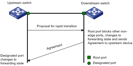
Figure 1-7 The MSTP rapid transition mechanism
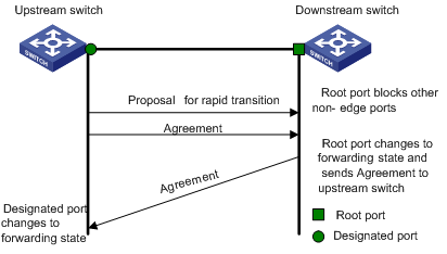
The cooperation between MSTP and RSTP is limited in the process of rapid transition. For example, when the upstream switch adopts RSTP, the downstream switch adopts MSTP and the downstream switch does not support RSTP-compatible mode, the root port on the downstream switch receives no agreement packet from the upstream switch and thus sends no agreement packets to the upstream switch. As a result, the designated port of the upstream switch fails to transit rapidly and can only turn to the forwarding state after a period twice the forward delay.
Some other manufacturers' switches adopt proprietary spanning tree protocols that are similar to RSTP in the way to implement rapid transition on designated ports. When a switch of this kind operating as the upstream switch connects with a H3C series switch running MSTP, the upstream designated port fails to change its state rapidly.
The rapid transition feature is developed to resolve this problem. When a H3C series switch running MSTP is connected in the upstream direction to another manufacturer's switch running proprietary spanning tree protocols, you can enable the rapid transition feature on the ports of the H3C series switch operating as the downstream switch. Among these ports, those operating as the root ports will then send agreement packets to their upstream ports after they receive proposal packets from the upstream designated ports, instead of waiting for agreement packets from the upstream switch. This enables designated ports of the upstream switch to change their states rapidly.
Configuring Rapid Transition
Configuration prerequisites
As shown in Figure 1-8, a H3C series switch is connected to another manufacturer's switch. The former operates as the downstream switch, and the latter operates as the upstream switch. The network operates normally.
The upstream switch is running a proprietary spanning tree protocol that is similar to RSTP in the way to implement rapid transition on designated ports. Port 1 is the designated port.
The downstream H3C switch is running MSTP. Port 2 is the root port.
Figure 1-8 Network diagram for rapid transition configuration
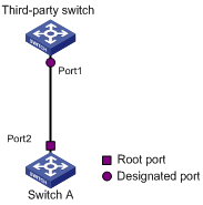
Configuration procedure
1) Configure the rapid transition feature in system view
Follow these steps to configure the rapid transition feature in system view:
|
To do... |
Use the command... |
Remarks |
|
Enter system view |
system-view |
— |
|
Enable the rapid transition feature |
stp interface interface-type interface-number no-agreement-check |
Required By default, the rapid transition feature is disabled on a port. |
2) Configure the rapid transition feature in Ethernet port view
Follow these steps to configure the rapid transition feature in Ethernet port view:
|
To do... |
Use the command... |
Remarks |
|
Enter system view |
system-view |
— |
|
Enter Ethernet port view |
interface interface-type interface-number |
— |
|
Enable the rapid transition feature |
stp no-agreement-check |
Required By default, the rapid transition feature is disabled on a port. |
![]()
l The rapid transition feature can be enabled on only root ports or alternate ports.
l If you configure the rapid transition feature on a designated port, the feature does not take effect on the port.
Configuring VLAN-VPN Tunnel
Introduction
The VLAN-VPN Tunnel function enables STP packets to be transparently transmitted between geographically dispersed customer networks through specified VLAN VPNs in service provider networks, through which spanning trees can be generated across these customer networks and are independent of those of the service provider network.
As shown in Figure 1-9, the upper part is the service provider network, and the lower part comprises the customer networks. The service provider network comprises packet input/output devices, and the customer network has networks A and B. On the service provider network, configure the arriving STP packets at the input device to have MAC addresses in a special format, and reconvert them back to their original formats at the output device. This is how transparent transmission is implemented over the service provider network.
Figure 1-9 VLAN-VPN tunnel network hierarchy
Configuring VLAN-VPN tunnel
Follow these steps to configure VLAN-VPN tunnel:
|
To do... |
Use the command... |
Remarks |
|
Enter system view |
system-view |
— |
|
Enable MSTP globally |
stp enable |
— |
|
Enable the VLAN-VPN tunnel function globally |
vlan-vpn tunnel |
Required The VLAN-VPN tunnel function is disabled by default. |
|
Enter Ethernet port view |
interface interface-type interface-number |
Make sure that you enter the Ethernet port view of the port for which you want to enable the VLAN-VPN tunnel function. |
|
Enable the VLAN VPN function for the Ethernet port |
vlan-vpn enable |
Required By default, the VLAN VPN function is disabled on all ports. |
![]()
l The VLAN-VPN tunnel function can be enabled on STP-enabled devices only.
l To enable the VLAN-VPN tunnel function, make sure the links between service provider networks are trunk links.
l If a fabric port exists on a switch, you cannot enable the VLAN VPN function on any port of the switch.
STP Maintenance Configuration
Introduction
In a large-scale network with MSTP enabled, there may be many MSTP instances, and so the status of a port may change frequently. In this case, maintenance personnel may expect that log/trap information is output to the log host when particular ports fail, so that they can check the status changes of those ports through alarm information.
Enabling Log/Trap Output for Ports of MSTP Instance
Follow these steps to enable log/trap output for ports of MSTP instance:
|
To do... |
Use the command... |
Remarks |
|
Enter system view |
system-view |
— |
|
Enable log/trap output for the ports of a specified instance |
stp [ instance instance-id ] portlog |
Required By default, log/trap output is disabled for the ports of all instances. |
|
Enable log/trap output for the ports of all instances |
stp portlog all |
Required By default, log/trap output is disabled for the ports of all instances. |
Configuration Example
# Enable log/trap output for the ports of instance 1.
<Sysname> system-view
[Sysname] stp instance 1 portlog
# Enable log/trap output for the ports of all instances.
<Sysname> system-view
[Sysname] stp portlog all
Enabling Trap Messages Conforming to 802.1d Standard
A switch sends trap messages conforming to 802.1d standard to the network management device in the following two cases:
l The switch becomes the root bridge of an instance.
l Network topology changes are detected.
Configuration procedure
Follow these steps to enable trap messages conforming to 802.1d standard:
|
To do... |
Use the command... |
Remarks |
|
Enter system view |
system-view |
— |
|
Enable trap messages conforming to 802.1d standard in an instance |
stp [ instance instance-id ] dot1d-trap [ newroot | topologychange ] enable |
Required |
Configuration example
# Enable a switch to send trap messages conforming to 802.1d standard to the network management device when the switch becomes the root bridge of instance 1.
<Sysname> system-view
[Sysname] stp instance 1 dot1d-trap newroot enable
Displaying and Maintaining MSTP
|
To do... |
Use the command... |
Remarks |
|
Display the state and statistics information about spanning trees of the current device |
display stp [ instance instance-id ] [ interface interface-list | slot slot-number ] [ brief ] |
Available in any view |
|
Display region configuration |
display stp region-configuration |
|
|
Display information about the ports that are shut down by STP protection |
display stp portdown |
|
|
Display information about the ports that are blocked by STP protection |
display stp abnormalport |
|
|
Display information about the root port of the instance where the switch reside |
display stp root |
|
|
Clear statistics about MSTP |
reset stp [ interface interface-list ] |
Available in user view |
MSTP Configuration Example
Network requirements
Implement MSTP in the network shown in Figure 1-10 to enable packets of different VLANs to be forwarded along different MSTIs. The detailed configurations are as follows:
l All switches in the network belong to the same MST region.
l Packets of VLAN 10, VLAN 30, VLAN 40, and VLAN 20 are forwarded along MSTI 1, MSTI 3, MSTI 4, and MSTI 0 respectively.
In this network, Switch A and Switch B operate on the convergence layer; Switch C and Switch D operate on the access layer. VLAN 10 and VLAN 30 are limited in the convergence layer and VLAN 40 is limited in the access layer. Switch A and Switch B are configured as the root bridges of MSTI 1 and MSTI 3 respectively. Switch C is configured as the root bridge of MSTI 4.
Network diagram
Figure 1-10 Network diagram for MSTP configuration
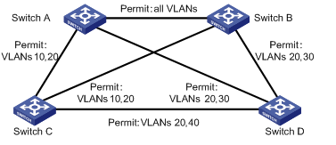
![]()
The word “permit” shown in Figure 1-10 means the corresponding link permits packets of specific VLANs.
Configuration procedure
1) Configure Switch A
# Enter MST region view.
<Sysname> system-view
[Sysname] stp region-configuration
# Configure the region name, VLAN-to-MSTI mapping table, and revision level for the MST region.
[Sysname-mst-region] region-name example
[Sysname-mst-region] instance 1 vlan 10
[Sysname-mst-region] instance 3 vlan 30
[Sysname-mst-region] instance 4 vlan 40
[Sysname-mst-region] revision-level 0
# Activate the settings of the MST region manually.
[Sysname-mst-region] active region-configuration
# Specify Switch A as the root bridge of MSTI 1.
[Sysname] stp instance 1 root primary
2) Configure Switch B
# Enter MST region view.
<Sysname> system-view
[Sysname] stp region-configuration
# Configure the region name, VLAN-to-MSTI mapping table, and revision level for the MST region.
[Sysname-mst-region] region-name example
[Sysname-mst-region] instance 1 vlan 10
[Sysname-mst-region] instance 3 vlan 30
[Sysname-mst-region] instance 4 vlan 40
[Sysname-mst-region] revision-level 0
# Activate the settings of the MST region manually.
[Sysname-mst-region] active region-configuration
# Specify Switch B as the root bridge of MSTI 3.
[Sysname] stp instance 3 root primary
3) Configure Switch C.
# Enter MST region view.
<Sysname> system-view
[Sysname] stp region-configuration
# Configure the MST region.
[Sysname-mst-region] region-name example
[Sysname-mst-region] instance 1 vlan 10
[Sysname-mst-region] instance 3 vlan 30
[Sysname-mst-region] instance 4 vlan 40
[Sysname-mst-region] revision-level 0
# Activate the settings of the MST region manually.
[Sysname-mst-region] active region-configuration
# Specify Switch C as the root bridge of MSTI 4.
[Sysname] stp instance 4 root primary
4) Configure Switch D
# Enter MST region view.
<Sysname> system-view
[Sysname] stp region-configuration
# Configure the MST region.
[Sysname-mst-region] region-name example
[Sysname-mst-region] instance 1 vlan 10
[Sysname-mst-region] instance 3 vlan 30
[Sysname-mst-region] instance 4 vlan 40
[Sysname-mst-region] revision-level 0
# Activate the settings of the MST region manually.
[Sysname-mst-region] active region-configuration
VLAN-VPN tunnel Configuration Example
Network requirements
l Switch C and Switch D are the access devices for the service provider network.
l Switch A and Switch B are the access devices for the customer networks.
l Switch C and Switch D are connected to each other through the configured trunk ports of the switches. The VLAN-VPN tunnel function is enabled in system view, thus implementing transparent transmission between the customer networks and the service provider network.
Network diagram
Figure 1-11 Network diagram for VLAN-VPN tunnel configuration
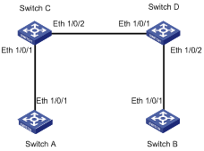
Configuration procedure
1) Configure Switch A
# Enable MSTP.
<Sysname> system-view
[Sysname] stp enable
# Add Ethernet 1/0/1 to VLAN 10.
[Sysname] vlan 10
[Sysname-Vlan10] port Ethernet 1/0/1
2) Configure Switch B
# Enable MSTP.
<Sysname> system-view
[Sysname] stp enable
# Add Ethernet 1/0/1 to VLAN 10.
[Sysname] vlan 10
[Sysname-Vlan10] port Ethernet 1/0/1
3) Configure Switch C
# Enable MSTP.
<Sysname> system-view
[Sysname] stp enable
# Enable the VLAN-VPN tunnel function.
[Sysname] vlan-vpn tunnel
# Add Ethernet 1/0/1 to VLAN 10.
[Sysname] vlan 10
[Sysname-Vlan10] port Ethernet 1/0/1
[Sysname-Vlan10] quit
# Disable STP on Ethernet 1/0/1 and then enable the VLAN VPN function on it.
[Sysname] interface Ethernet 1/0/1
[Sysname-Ethernet1/0/1] port access vlan 10
[Sysname-Ethernet1/0/1] vlan-vpn enable
[Sysname-Ethernet1/0/1] quit
# Configure Ethernet 1/0/2 as a trunk port.
[Sysname] interface Ethernet 1/0/2
[Sysname-Ethernet1/0/2] port link-type trunk
# Add the trunk port to all VLANs.
[Sysname-Ethernet1/0/2] port trunk permit vlan all
4) Configure Switch D
# Enable MSTP.
<Sysname> system-view
[Sysname] stp enable
# Enable the VLAN-VPN tunnel function.
[Sysname] vlan-vpn tunnel
# Add Ethernet 1/0/2 to VLAN 10.
[Sysname] vlan 10
[Sysname-Vlan10] port Ethernet 1/0/2
# Disable STP on Ethernet 1/0/2 and then enable the VLAN VPN function on it.
[Sysname] interface Ethernet 1/0/2
[Sysname-Ethernet1/0/2] port access vlan 10
[Sysname-Ethernet1/0/2] stp disable
[Sysname-Ethernet1/0/2] quit
# Configure Ethernet 1/0/1 as a trunk port.
[Sysname] interface Ethernet 1/0/1
[Sysname-Ethernet1/0/1] port link-type trunk
# Add the trunk port to all VLANs.
[Sysname-Ethernet1/0/1] port trunk permit vlan all