- Table of Contents
-
- H3C S3600 Operation Manual-Release 1602(V1.02)
- 00-1Cover
- 00-2Product Overview
- 01-CLI Operation
- 02-Login Operation
- 03-Configuration File Management Operation
- 04-VLAN Operation
- 05-IP Address and Performance Operation
- 06-Voice VLAN Operation
- 07-GVRP Operation
- 08-Port Basic Configuration Operation
- 09-Link Aggregation Operation
- 10-Port Isolation Operation
- 11-Port Security-Port Binding Operation
- 12-DLDP Operation
- 13-MAC Address Table Management Operation
- 14-Auto Detect Operation
- 15-MSTP Operation
- 16-Routing Protocol Operation
- 17-Multicast Operation
- 18-802.1x and System Guard Operation
- 19-AAA Operation
- 20-Web Authentication Operation
- 21-MAC Address Authentication Operation
- 22-VRRP Operation
- 23-ARP Operation
- 24-DHCP Operation
- 25-ACL Operation
- 26-QoS-QoS Profile Operation
- 27-Web Cache Redirection Operation
- 28-Mirroring Operation
- 29-IRF Fabric Operation
- 30-Cluster Operation
- 31-PoE-PoE Profile Operation
- 32-UDP Helper Operation
- 33-SNMP-RMON Operation
- 34-NTP Operation
- 35-SSH Operation
- 36-File System Management Operation
- 37-FTP-SFTP-TFTP Operation
- 38-Information Center Operation
- 39-System Maintenance and Debugging Operation
- 40-VLAN-VPN Operation
- 41-HWPing Operation
- 42-IPv6 Management Operation
- 43-DNS Operation
- 44-Smart Link-Monitor Link Operation
- 45-Access Management Operation
- 46-Appendix
- Related Documents
-
| Title | Size | Download |
|---|---|---|
| 04-VLAN Operation | 300.19 KB |
Table of Contents
Assigning an Ethernet Port to Specified VLANs
Configuring the Default VLAN ID for a Port
Introduction to Protocol-Based VLAN
Encapsulation Format of Ethernet Data
Procedure for the Switch to Judge Packet Protocol
Implementation of Protocol-Based VLAN
Basic VLAN Interface Configuration
Port-Based VLAN Configuration Task List
Configuring the Link Type of an Ethernet Port
Assigning an Ethernet Port to a VLAN
Configuring the Default VLAN for a Port
Displaying and Maintaining Port-Based VLAN
Port-Based VLAN Configuration Example
Configuring a Protocol-Based VLAN
Protocol-Based VLAN Configuration Task List
Configuring a Protocol Template for a Protocol-Based VLAN
Associating a Port with a Protocol-Based VLAN
Displaying Protocol-Based VLAN Configuration
Protocol-Based VLAN Configuration Example
This chapter covers these topics:
VLAN Overview
Introduction to VLAN
The traditional Ethernet is a broadcast network, where all hosts are in the same broadcast domain and connected with each other through hubs or switches. Hubs and switches, which are the basic network connection devices, have limited forwarding functions.
l A hub is a physical layer device without the switching function, so it forwards the received packet to all ports except the inbound port of the packet.
l A switch is a link layer device which can forward a packet according to the MAC address of the packet. However, when the switch receives a broadcast packet or an unknown unicast packet whose MAC address is not included in the MAC address table of the switch, it will forward the packet to all the ports except the inbound port of the packet.
The above scenarios could result in the following network problems.
l Large quantity of broadcast packets or unknown unicast packets may exist in a network, wasting network resources.
l A host in the network receives a lot of packets whose destination is not the host itself, causing potential serious security problems.
Isolating broadcast domains is the solution for the above problems. The traditional way is to use routers, which forward packets according to the destination IP address and does not forward broadcast packets in the link layer. However, routers are expensive and provide few ports, so they cannot split the network efficiently. Therefore, using routers to isolate broadcast domains has many limitations.
The Virtual Local Area Network (VLAN) technology is developed for switches to control broadcasts in LANs.
A VLAN can span multiple physical spaces. This enables hosts in a VLAN to be located in different physical locations.
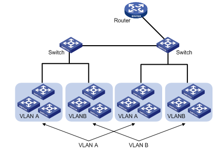
By creating VLANs in a physical LAN, you can divide the LAN into multiple logical LANs, each of which has a broadcast domain of its own. Hosts in the same VLAN communicate in the traditional Ethernet way. However, hosts in different VLANs cannot communicate with each other directly but need the help of network layer devices, such as routers and Layer 3 switches. Figure 1-1 illustrates a VLAN implementation.
Figure 1-1 A VLAN implementation
Advantages of VLANs
Compared with traditional Ethernet technology, VLAN technology delivers the following benefits:
l Confining broadcast traffic within individual VLANs. This saves bandwidth and improves network performance.
l Improving LAN security. By assigning user groups to different VLANs, you can isolate them at Layer 2. To enable communication between VLANs, routers or Layer 3 switches are required.
l Flexible virtual workgroup creation. As users from the same workgroup can be assigned to the same VLAN regardless of their physical locations, network construction and maintenance is much easier and more flexible.
VLAN Fundamentals
VLAN tag
To enable a Layer-2 switch to identify frames of different VLANs, a VLAN tag field is inserted into the data link layer encapsulation.
The format of VLAN-tagged frames is defined in IEEE 802.1Q issued by IEEE in 1999.
In the header of a traditional Ethernet data frame, the field after the destination MAC address and the source MAC address (DA&SA) is the Type field indicating the upper layer protocol type, as shown in Figure 1-2.
Figure 1-2 Encapsulation format of traditional Ethernet frames
![]()
IEEE 802.1Q inserts a four-byte VLAN tag after the DA&SA field, as shown in Figure 1-3.
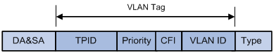
A VLAN tag comprises four fields: tag protocol identifier (TPID), priority, canonical format indicator (CFI), and VLAN ID.
l The 16-bit TPID field with a value of 0x8100 indicates that the frame is VLAN tagged. On the H3C series Ethernet switches, the default TPID is 0x8100.
l The 3-bit priority field indicates the 802.1p priority of the frame. Refer to the “QoS-QoS profile” part of this manual for details.
l The 1-bit CFI field specifies whether the MAC addresses are encapsulated in the canonical format for the receiving device to correctly interpret the MAC addresses. Value 0 indicates that the MAC addresses are encapsulated in canonical format; value 1 indicates that the MAC addresses are encapsulated in non-canonical format. The field is set to 0 by default.
l The 12-bit VLAN ID field identifies the VLAN the frame belongs to. The VLAN ID range is 0 to 4095. As 0 and 4095 are reserved by the protocol, a VLAN ID actually ranges from 1 to 4094.
![]()
The Ethernet II encapsulation format is used here. Besides the Ethernet II encapsulation format, other encapsulation formats such as 802.2 LLC and 802.2 SNAP are also supported by Ethernet. The VLAN tag fields are also added to frames encapsulated in these formats for VLAN identification. Refer to section Encapsulation Format of Ethernet Data for 802.2/802.3 encapsulation format.
VLAN ID identifies the VLAN to which a packet belongs. When a switch receives a packet carrying no VLAN tag, the switch encapsulates a VLAN tag with the default VLAN ID of the inbound port for the packet, and sends the packet to the default VLAN of the inbound port for transmission. For the details about setting the default VLAN of a port, refer to Configuring the Default VLAN ID for a Port.
MAC address learning mechanism of VLANs
Switches forward packets according to the destination MAC addresses of the packets. So that switches maintain a table called MAC address forwarding table to record the source MAC addresses of the received packets and the corresponding ports receiving the packets for consequent packet forwarding. The process of recording is called MAC address learning.
After VLANs are configured on a switch, the MAC address learning of the switch has the following two modes.
l Shared VLAN Learning (SVL): the switch records all the MAC address entries learnt by ports in all VLANs to a shared MAC address forwarding table. Packets received on any port of any VLAN are forwarded according to this table.
l Independent VLAN Learning (IVL): the switch maintains an independent MAC address forwarding table for each VLAN. The source MAC address of a packet received on a port of a VLAN is recorded to the MAC address forwarding table of this VLAN only, and packets received on a port of a VLAN are forwarded according to the VLAN’s own MAC address forwarding table.
VLAN Interface
Hosts in different VLANs cannot communicate with each other directly unless routers or Layer 3 switches are used to do Layer 3 forwarding. The S3600 series Ethernet switches support VLAN interfaces configuration to forward packets in Layer 3.
VLAN interface is a virtual interface in Layer 3 mode, used to realize the layer 3 communication between different VLANs, and does not exist on a switch as a physical entity. Each VLAN has a VLAN interface, which can forward packets of the local VLAN to the destination IP addresses at the network layer. Normally, since VLANs can isolate broadcast domains, each VLAN corresponds to an IP network segment. And a VLAN interface serves as the gateway of the segment to forward packets in Layer 3 based on IP addresses.
VLAN Classification
Depending on how VLANs are established, VLANs fall into the following six categories.
l Port-based VLANs
l MAC address-based VLANs
l Protocol-based VLANs
l IP-subnet-based VLANs
l Policy-based VLANs
l Other types
At present, the S3600 series switches support the port-based and protocol-based VLANs.
Port-Based VLAN
Port-based VLAN technology introduces the simplest way to classify VLANs. You can assign the ports on the device to different VLANs. Thus packets received on a port will be transmitted through the corresponding VLAN only, so as to isolate hosts to different broadcast domains and divide them into different virtual workgroups.
Ports on Ethernet switches have the three link types: access, trunk, and hybrid. For the three types of ports, the process of being added into a VLAN and the way of forwarding packets are different.
Port-based VLANs are easy to implement and manage and applicable to hosts with relatively fixed positions.
Link Types of Ethernet Ports
The link type of an Ethernet port on the S3600 series can be one of the following:
l Access: An access port can belong to only one VLAN, and is generally connected to a user PC.
l Trunk: A trunk port can belong to more than one VLAN. It can forward packets for multiple VLANs, and is generally connected to another switch.
l Hybrid: A hybrid port can belong to more than one VLAN to forward packets for multiple VLANs. It can be connected to either a switch or a user PC.
![]()
A hybrid port allows the packets of multiple VLANs to be sent untagged, but a trunk port only allows the packets of the default VLAN to be sent untagged.
The three types of ports can coexist on the same device.
Assigning an Ethernet Port to Specified VLANs
You can assign an Ethernet port to a VLAN to forward packets for the VLAN, thus allowing the VLAN on the current switch to communicate with the same VLAN on the peer switch.
An access port can be assigned to only one VLAN, while a hybrid or trunk port can be assigned to multiple VLANs.
![]()
Before assigning an access or hybrid port to a VLAN, create the VLAN first.
Configuring the Default VLAN ID for a Port
An access port can belong to only one VLAN. Therefore, the VLAN an access port belongs to is also the default VLAN of the access port. A hybrid/trunk port can belong to multiple VLANs, so you should configure a default VLAN ID for the port.
After a port is added to a VLAN and configured with a default VLAN, the port receives and sends packets in a way related to its link type. For detailed description, refer to the following tables:
Table 1-1 Packet processing of an access port
|
Processing of an incoming packet |
Processing of an outgoing packet |
|
|
For an untagged packet |
For a tagged packet |
|
|
Receive the packet and tag the packet with the default VLAN tag. |
l If the VLAN ID is just the default VLAN ID, receive the packet. l If the VLAN ID is not the default VLAN ID, discard the packet. |
Strip the tag from the packet and send the packet. |
Table 1-2 Packet processing of a trunk port
|
Processing of an incoming packet |
Processing of an outgoing packet |
|
|
For an untagged packet |
For a tagged packet |
|
|
l If the port has already been added to its default VLAN, tag the packet with the default VLAN tag and then forward the packet. l If the port has not been added to its default VLAN, discard the packet. |
l If the VLAN ID is one of the VLAN IDs allowed to pass through the port, receive the packet. l If the VLAN ID is not one of the VLAN IDs allowed to pass through the port, discard the packet. |
l If the VLAN ID is just the default VLAN ID, strip off the tag and send the packet. l If the VLAN ID is not the default VLAN ID, keep the original tag unchanged and send the packet. |
Table 1-3 Packet processing of a hybrid port
|
Processing of an incoming packet |
Processing of an outgoing packet |
|
|
For an untagged packet |
For a tagged packet |
|
|
l If the port has already been added to its default VLAN, tag the packet with the default VLAN tag and then forward the packet. l If the port has not been added to its default VLAN, discard the packet. |
l If the VLAN ID is one of the VLAN IDs allowed to pass through the port, receive the packet. l If the VLAN ID is not one of the VLAN IDs allowed to pass through the port, discard the packet. |
Send the packet if the VLAN ID is allowed to pass through the port. Use the port hybrid vlan command to configure whether the port keeps or strips off the tags when sending packets of a VLAN (including the default VLAN). |
Protocol-Based VLAN
Introduction to Protocol-Based VLAN
Protocol-based VLAN is also known as protocol VLAN, which is another way to classify VLANs. Through the protocol-based VLANs, the switch can analyze the received packets carrying no VLAN tag on the port and match the packets with the user-defined protocol template automatically according to different encapsulation formats and the values of specific fields. If a packet is matched, the switch will add a corresponding VLAN tag to it automatically. Thus, data of specific protocol is assigned automatically to the corresponding VLAN for transmission.
This feature is used for binding the ToS provided in the network to VLAN to facilitate management and maintenance.
Encapsulation Format of Ethernet Data
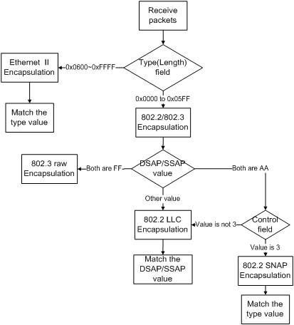
This section introduces the common encapsulation formats of Ethernet data for you to understand the procedure for the switch to identify the packet protocols.
Ethernet II and 802.2/802.3 encapsulation
There are two encapsulation types of Ethernet packets: Ethernet II defined by RFC 894 and 802.2/802.3 defined by RFC 1042. The two encapsulation formats are described in the following figures.
Ethernet II packet:
Figure 1-4 Ethernet II encapsulation format
![]()
802.2/802.3 packet:
Figure 1-5 802.2/802.3 encapsulation format
![]()
In the two figures, DA and SA refer to the destination MAC address and source MAC address of the packet respectively. The number in the bracket indicates the field length in bytes.
The maximum length of an Ethernet packet is 1500 bytes, that is, 0x05DC in hexadecimal, so the length field in 802.2/802.3 encapsulation is in the range of 0x0000 to 0x05DC.
Whereas, the type field in Ethernet II encapsulation is in the range of 0x0600 to 0xFFFF.
Packets with the value of the type or length field being in the range 0x05DD to 0x05FF are regarded as illegal packets and thus discarded directly.
The switch identifies whether a packet is an Ethernet II packet or an 802.2/802.3 packet according to the ranges of the two fields.
![]()
The H3C S3600 series switches recognize packets with the value of the type field being in the range 0x05DD to 0x05FF as 802.2/802.3 encapsulated packets.
Extended encapsulation formats of 802.2/802.3 packets
802.2/802.3 packets have the following three extended encapsulation formats:
l 802.3 raw encapsulation: only the length field is encapsulated after the source and destination address field, followed by the upper layer data. No other fields are included.
Figure 1-6 802.3 raw encapsulation format
![]()
Currently, only IPX supports 802.3 raw encapsulation, featuring with the value of the two bytes after the length field being 0xFFFF.
l 802.2 Logical Link Control (LLC) encapsulation: the length field, the destination service access point (DSAP) field, the source service access point (SSAP) field and the control field are encapsulated after the source and destination address field. The value of the control field is always 3.
Figure 1-7 802.2 LLC encapsulation format
![]()
The DSAP field and the SSAP field in the 802.2 LLC encapsulation are used to identify the upper layer protocol. For example, if the two fields are both 0xE0, the upper layer protocol is IPX protocol.
l 802.2 Sub-Network Access Protocol (SNAP) encapsulation: encapsulates packets according to the 802.3 standard packet format, including the length, DSAP, SSAP, control, organizationally unique identifier (OUI), and protocol-ID (PID) fields.
Figure 1-8 802.2 SNAP encapsulation format
![]()
In 802.2 SNAP encapsulation format, the values of the DSAP field and the SSAP field are always 0xAA, and the value of the control field is always 3.
The switch differentiates between 802.2 LLC encapsulation and 802.2 SNAP encapsulation according to the values of the DSAP field and the SSAP field.
![]()
When the OUI is 00-00-00 in 802.2 SNAP encapsulation, the PID field has the same meaning as the type field in Ethernet II encapsulation, which both refer to globally unique protocol number. Such encapsulation is also known as SNAP RFC 1042 encapsulation, which is standard SNAP encapsulation. The SNAP encapsulation mentioned in this chapter refers to SNAP RFC 1042 encapsulation.
Procedure for the Switch to Judge Packet Protocol
Figure 1-9 Protocol identification procedure
Encapsulation Formats
Table 1-4 lists the encapsulation formats supported by some protocols. In brackets are type values of these protocols.
Table 1-4 Encapsulation formats
|
Encapsulation (left) |
Ethernet II |
802.3 raw |
802.2 LLC |
802.2 SNAP |
|
Protocol (down) |
||||
|
IP (0x0800) |
Supported |
Not supported |
Not supported |
Supported |
|
IPX (0x8137) |
Supported |
Supported |
Supported |
Supported |
|
AppleTalk (0x809B) |
Supported |
Not supported |
Not supported |
Supported |
Implementation of Protocol-Based VLAN
S3600 series Ethernet switches assign the packet to the specific VLAN by matching the packet with the protocol template.
The protocol template is the standard to determine the protocol to which a packet belongs. Protocol templates include standard templates and user-defined templates:
l The standard template adopts the RFC-defined packet encapsulation formats and values of some specific fields as the matching criteria.
l The user-defined template adopts the user-defined encapsulation formats and values of some specific fields as the matching criteria.
After configuring the protocol template, you must add a port to the protocol-based VLAN and associate this port with the protocol template. This port will add VLAN tags to the packets based on protocol types. The port in the protocol-based VLAN must be connected to a client. However, a common client cannot process VLAN-tagged packets. In order that the client can process the packets out of this port, you must configure the port in the protocol-based VLAN as a hybrid port and configure the port to remove VLAN tags when forwarding packets of all VLANs.
When configuring a VLAN, go to these sections for information you are interested in:
l Configuring a Port-Based VLAN
l Configuring a Protocol-Based VLAN
VLAN Configuration
VLAN Configuration Task List
Complete the following tasks to configure VLAN:
|
Task |
Remarks |
|
Required |
|
|
Optional |
|
|
Optional |
Basic VLAN Configuration
Follow these steps to perform basic VLAN configuration:
|
To do... |
Use the command... |
Remarks |
|
Enter system view |
system-view |
— |
|
Create multiple VLANs in batch |
vlan { vlan-id1 to vlan-id2 | all } |
Optional |
|
Create a VLAN and enter VLAN view |
vlan vlan-id |
Required By default, there is only one VLAN, that is, the default VLAN (VLAN 1). |
|
Assign a name for the current VLAN |
name text |
Optional By default, the name of a VLAN is its VLAN ID. VLAN 0001 for example. |
|
Specify the description string of the current VLAN |
description text |
Optional By default, the description string of a VLAN is its VLAN ID. VLAN 0001 for example. |
![]()
l VLAN 1 is the system default VLAN, which needs not to be created and cannot be removed, either.
l The VLAN you created in the way described above is a static VLAN. On the switch, there are dynamic VLANs which are registered through GVRP. For details, refer to “GVRP” part of this manual.
l When you use the vlan command to create VLANs, if the destination VLAN is an existing dynamic VLAN, it will be transformed into a static VLAN and the switch will output the prompt information.
Basic VLAN Interface Configuration
Configuration prerequisites
Before configuring a VLAN interface, create the corresponding VLAN.
Configuration procedure
Follow these steps to perform basic VLAN interface configuration:
|
To do... |
Use the command... |
Remarks |
|
Enter system view |
system-view |
— |
|
Create a VLAN interface and enter VLAN interface view |
interface Vlan-interface vlan-id |
Required By default, there is no VLAN interface on a switch. |
|
Specify the description string for the current VLAN interface |
description text |
Optional By default, the description string of a VLAN interface is the name of this VLAN interface. Vlan-interface1 Interface for example. |
|
Disable the VLAN interface |
shutdown |
Optional By default, the VLAN interface is enabled. In this case, the VLAN interface’s status is determined by the status of the ports in the VLAN, that is, if all ports of the VLAN are down, the VLAN interface is down (disabled); if one or more ports of the VLAN are up, the VLAN interface is up (enabled). If you disable the VLAN interface, the VLAN interface will always be down, regardless of the status of the ports in the VLAN. |
|
Enable the VLAN Interface |
undo shutdown |
![]()
The operation of enabling/disabling a VLAN’s VLAN interface does not influence the physical status of the Ethernet ports belonging to this VLAN.
Displaying VLAN Configuration
|
To do... |
Use the command... |
Remarks |
|
Display the VLAN interface information |
display interface Vlan-interface [ vlan-id ] |
Available in any view. |
|
Display the VLAN information |
display vlan [ vlan-id [ to vlan-id ] | all | dynamic | static ] |
Configuring a Port-Based VLAN
Port-Based VLAN Configuration Task List
Complete these tasks to configure a port-based VLAN:
|
Task |
Remarks |
|
Optional |
|
|
Required |
|
|
Optional |
Configuring the Link Type of an Ethernet Port
Follow these steps to configure the link type of an Ethernet port:
|
To do… |
Use the command… |
Remarks |
|
Enter system view |
system-view |
— |
|
Enter Ethernet port view |
interface interface-type interface-number |
— |
|
Configure the port link type |
port link-type { access | hybrid | trunk } |
Required The link type of an Ethernet port is access by default. |
![]()
l To change the link type of a port from trunk to hybrid or vice versa, you need to set the link type to access first.
l You can use the port link-type irf-fabric command to configure fabric ports. For information about this command, refer to the IRF Fabric module in this manual.
Assigning an Ethernet Port to a VLAN
You can assign an Ethernet port to a VLAN in Ethernet port view or VLAN view.
1) In Ethernet port view
Follow these steps to assign an Ethernet port to one or multiple VLANs:
|
To do… |
Use the command… |
Remarks |
|
|
Enter system view |
system-view |
— |
|
|
Enter Ethernet port view |
interface interface-type interface-number |
— |
|
|
Assign the port to one or multiple VLANs |
Access port |
port access vlan vlan-id |
Optional By default, all Ethernet ports belong to VLAN 1. |
|
Trunk port |
port trunk permit vlan { vlan-id-list | all } |
||
|
Hybrid port |
port hybrid vlan vlan-id-list { tagged | untagged } |
||
![]()
When assigning an access or hybrid port to a VLAN, make sure the VLAN already exists.
2) In VLAN view
Follow these steps to assign one or multiple access ports to a VLAN in VLAN view:
|
To do… |
Use the command… |
Remarks |
|
Enter system view |
system-view |
— |
|
Enter VLAN view |
vlan vlan-id |
Required If the specified VLAN does not exist, this command creates the VLAN first. |
|
Assign the specified access port or ports to the current VLAN |
port interface-list |
Required By default, all ports belong to VLAN 1. |
Configuring the Default VLAN for a Port
Because an access port can belong to its default VLAN only, there is no need for you to configure the default VLAN for an access port.
This section describes how to configure a default VLAN for a trunk or hybrid port.
Follow these steps to configure the default VLAN for a port:
|
To do… |
Use the command… |
Remarks |
|
|
Enter system view |
system-view |
— |
|
|
Enter Ethernet port view |
interface interface-type interface-number |
— |
|
|
Configure the default VLAN for the port |
Trunk port |
port trunk pvid vlan vlan-id |
Optional VLAN 1 is the default VLAN by default. |
|
Hybrid port |
port hybrid pvid vlan vlan-id |
||
![]()
l After configuring the default VLAN for a trunk or hybrid port, you need to use the port trunk permit command or the port hybrid vlan command to configure the port to allow traffic of the default VLAN to pass through. Otherwise, the port cannot forward traffic of the default VLAN, nor can it receive VLAN untagged packets.
l The local and remote trunk (or hybrid) ports must use the same default VLAN ID for the traffic of the default VLAN to be transmitted properly.
Displaying and Maintaining Port-Based VLAN
|
To do… |
Use the command… |
Remarks |
|
Display the hybrid or trunk ports |
display port { hybrid | trunk } |
Available in any view. |
Port-Based VLAN Configuration Example
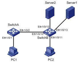
Network requirements
l As shown in Figure 2-1, Switch A and Switch B connect to PC 1/PC 2 and Server 1/Server 2 used by different departments.
l To isolate data between different departments, PC 1 and Server 1 are assigned to VLAN 100 with the descriptive string being Dept1; PC 2 and Server 2 are assigned to VLAN 200 with the descriptive string being Dept2.
l Configure VLAN interfaces for the two VLANs on Switch A for forwarding data from PC 1 to Server 2 at Layer 3.
Network diagram
Figure 2-1 Network diagram for VLAN configuration
Configuration procedure
l Configure Switch A.
# Create VLAN 100, specify its descriptive string as Dept1, and add Ethernet 1/0/1 to VLAN 100.
<SwitchA> system-view
[SwitchA] vlan 100
[SwitchA-vlan100] description Dept1
[SwitchA-vlan100] port Ethernet 1/0/1
[SwitchA-vlan100] quit
# Create VLAN 200, and specify its descriptive string as Dept2.
[SwitchA] vlan 200
[SwitchA-vlan200] description Dept2
[SwitchA-vlan200] quit
[SwitchA] interface Vlan-interface 100
[SwitchA-Vlan-interface100] ip address 192.168.1.1 24
[SwitchA-Vlan-interface100] quit
[SwitchA] interface Vlan-interface 200
[SwitchA-Vlan-interface200] ip address 192.168.2.1 24
l Configure Switch B.
# Create VLAN 100, specify its descriptive string as Dept1, and add Ethernet 1/0/13 to VLAN 100.
<SwitchB> system-view
[SwitchB] vlan 100
[SwitchB-vlan100] description Dept1
[SwitchB-vlan100] port Ethernet 1/0/13
[SwitchB-vlan103] quit
# Create VLAN 200, specify its descriptive string as Dept2 and add Ethernet 1/0/11 and Ethernet 1/0/12 to VLAN 200.
[SwitchB] vlan 200
[SwitchB-vlan200] description Dept2
[SwotchB-vlan200] port Ethernet1/0/11 Ethernet 1/0/12
[SwitchB-vlan200] quit
l Configure the link between Switch A and Switch B.
Because the link between Switch A and Switch B needs to transmit data of both VLAN 100 and VLAN 200, you can configure the ports at both ends of the link as trunk ports and permit packets of the two VLANs to pass through the two ports.
# Configure Ethernet 1/0/2 of Switch A.
[SwitchA] interface Ethernet 1/0/2
[SwitchA-Ethernet1/0/2] port link-type trunk
[SwitchA-Ethernet1/0/2] port trunk permit vlan 100
[SwitchA-Ethernet1/0/2] port trunk permit vlan 200
# Configure Ethernet 1/0/10 of Switch B.
[SwitchB] interface Ethernet 1/0/10
[SwitchB-Ethernet1/0/10] port link-type trunk
[SwitchB-Ethernet1/0/10] port trunk permit vlan 100
[SwitchB-Ethernet1/0/10] port trunk permit vlan 200
Configuring a Protocol-Based VLAN
Protocol-Based VLAN Configuration Task List
Complete these tasks to configure protocol-based VLAN:
|
Task |
Remarks |
|
Required |
|
|
Required |
|
|
Optional |
Configuring a Protocol Template for a Protocol-Based VLAN
Configuration prerequisites
Create a VLAN before configuring the VLAN as a protocol-based VLAN.
Configuration procedure
Follow these steps to configure the protocol template for a VLAN:
|
To do... |
Use the command... |
Remarks |
|
Enter system view |
system-view |
— |
|
Enter VLAN view |
vlan vlan-id |
— |
|
Configure the protocol template for the VLAN |
protocol-vlan [ protocol-index ] { at | ip | ipx { ethernetii | llc | raw | snap } | mode { ethernetii etype etype-id | llc dsap dsap-id ssap ssap-id | snap etype etype-id } } |
Required By default, no protocol template is configured for the VLAN. |
When configuring a protocol template for a protocol-based VLAN, use the at, ip or ipx keyword to configure a standard template to match AppleTalk, IP, and IPX packets respectively, and use the mode keyword to configure a user-defined template.
![]()
l Because the IP protocol is closely associated with the ARP protocol, you are recommended to configure the ARP protocol type when configuring the IP protocol type and associate the two protocol types with the same port to avoid that ARP packets and IP packets are not assigned to the same VLAN, which will cause IP address resolution failure.
l If you specify some special values for both the dsap-id and ssap-id arguments when configuring the user-defined template for IIc encapsulation, the matching packets will take the same encapsulation format as some standard type of packets. For example, when both dsap-id and ssap-id have a value of 0xFF, the encapsulation format will be the same as that of ipx raw packets; if they both have a value of 0xE0, the packet encapsulation format will be the same as that of ipx llc packets; if they both have a value of 0xAA, the packet encapsulation format will be the same as that of snap packets. To prevent two commands from processing packets of the same protocol type in different ways, the system does not allow you to set both the dsap-id and ssap-id arguments to 0xFF, 0xE0, or 0xAA.
l When you use the mode keyword to configure a user-defined protocol template, if you set the etype-id argument for ethernetii or snap packets to 0x0800, 0x8137, or 0x809B, the matching packets will take the same format as that of the IP, IPX, and AppleTalk packets respectively. To prevent two commands from processing packets of the same protocol type in different ways, the switch will prompt that you cannot set the etype-id argument for Ethernet II or snap packets to 0x0800, 0x8137, or 0x809B.
Associating a Port with a Protocol-Based VLAN
Configuration prerequisites
l The protocol template for the protocol-based VLAN is configured.
l The port is configured as a hybrid port, and the port is configured to remove VLAN tags when it forwards the packets of the protocol-based VLANs.
Configuration procedure
Follow these steps to associate a port with the protocol-based VLAN:
|
To do... |
Use the command... |
Remarks |
|
Enter system view |
system-view |
— |
|
Enter port view |
interface interface-type interface-number |
— |
|
Associate the port with the specified protocol-based VLAN |
port hybrid protocol-vlan vlan vlan-id { protocol-index [ to protocol-index-end ] | all } |
Required By default, a port is not associated with any protocol-based VLAN. |
Displaying Protocol-Based VLAN Configuration
|
To do... |
Use the command... |
Remarks |
|
Display the information about the protocol-based VLAN |
display vlan [ vlan-id [ to vlan-id ] | all | dynamic | static] |
Available in any view |
|
Display the protocol information and protocol indexes configured on the specified VLAN |
display protocol-vlan vlan { vlan-id [ to vlan-id ] | all } |
|
|
Display the protocol information and protocol indexes configured on the specified port |
display protocol-vlan interface { interface-type interface-number [ to interface-type interface-number ] | all } |
Protocol-Based VLAN Configuration Example
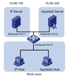
Network requirements
l As shown in Figure 2-2, Workroom connects to the LAN through port Ethernet 1/0/10 on the S3600 switch.
l IP network and AppleTalk network workstations (hosts) coexist in the Workroom.
l The S3600 switch connects to VLAN 100 (using IP network) through Ethernet 1/0/11 and to VLAN 200 (using AppleTalk network) through Ethernet 1/0/12.
l Configure the switch to automatically assign the IP and AppleTalk packets to proper VLANs for transmission, so as to ensure the normal communication between the workstations and servers.
Network diagram
Figure 2-2 Network diagram for protocol-based VLAN configuration
Configuration procedure
# Create VLAN 100 and VLAN 200, and add Ethernet 1/0/11 and Ethernet 1/0/12 to VLAN 100 and VLAN 200 respectively.
<Switch> system-view
[Switch] vlan 100
[Switch-vlan100] port Ethernet 1/0/11
[Switch-vlan100] quit
[Switch] vlan 200
[Switch-vlan200] port Ethernet 1/0/12
# Configure protocol templates for VLAN 200 and VLAN 100, matching AppleTalk protocol and IP protocol respectively.
[Switch-vlan200] protocol-vlan at
[Switch-vlan200] quit
[Switch] vlan 100
[Switch-vlan100] protocol-vlan ip
# To ensure the normal operation of IP network, you need to configure a user-defined protocol template for VLAN 100 to match the ARP protocol (assume Ethernet II encapsulation is adopted here).
[Switch-vlan100] protocol-vlan mode ethernetii etype 0806
# Display the created protocol-based VLANs and the protocol templates.
[Switch-vlan100] display protocol-vlan vlan all
VLAN ID: 100
VLAN Type: Protocol-based VLAN
Protocol Index Protocol Type
0 ip
1 ethernetii etype 0x0806
VLAN ID: 200
VLAN Type: Protocol-based VLAN
Protocol Index Protocol Type
0 at
# Configure Ethernet 1/0/10 as a hybrid port, which removes the VLAN tag of the packets of VLAN 100 and VLAN 200 before forwarding the packets.
[Switch-vlan100] quit
[Switch] interface Ethernet 1/0/10
[Switch-Ethernet1/0/10] port link-type hybrid
[Switch-Ethernet1/0/10] port hybrid vlan 100 200 untagged
# Associate Ethernet 1/0/10 with protocol template 0 and 1 of VLAN 100, and protocol template 0 of VLAN 200.
[Switch-Ethernet1/0/10] port hybrid protocol-vlan vlan 100 0 to 1
[Switch-Ethernet1/0/10] port hybrid protocol-vlan vlan 200 0
# Display the associations between Ethernet 1/0/10 and the VLAN protocol templates to verify your configuration.
[Switch-Ethernet1/0/10] display protocol-vlan interface Ethernet 1/0/10
Interface:Ethernet1/0/10
VLAN ID Protocol-Index Protocol-Type
100 0 ip
100 1 ethernetii etype 0x0806
200 0 at
The above output information indicates that Ethernet 1/0/10 has already been associated with the corresponding protocol templates of VLAN 100 and VLAN 200. Thus, packets from the IP and AppleTalk workstations can be automatically assigned to VLAN 100 and VLAN 200 respectively for transmission by matching the corresponding protocol templates, so as to realize the normal communication between workstations and servers.