- Table of Contents
-
- H3C S3600 Operation Manual-Release 1602(V1.02)
- 00-1Cover
- 00-2Product Overview
- 01-CLI Operation
- 02-Login Operation
- 03-Configuration File Management Operation
- 04-VLAN Operation
- 05-IP Address and Performance Operation
- 06-Voice VLAN Operation
- 07-GVRP Operation
- 08-Port Basic Configuration Operation
- 09-Link Aggregation Operation
- 10-Port Isolation Operation
- 11-Port Security-Port Binding Operation
- 12-DLDP Operation
- 13-MAC Address Table Management Operation
- 14-Auto Detect Operation
- 15-MSTP Operation
- 16-Routing Protocol Operation
- 17-Multicast Operation
- 18-802.1x and System Guard Operation
- 19-AAA Operation
- 20-Web Authentication Operation
- 21-MAC Address Authentication Operation
- 22-VRRP Operation
- 23-ARP Operation
- 24-DHCP Operation
- 25-ACL Operation
- 26-QoS-QoS Profile Operation
- 27-Web Cache Redirection Operation
- 28-Mirroring Operation
- 29-IRF Fabric Operation
- 30-Cluster Operation
- 31-PoE-PoE Profile Operation
- 32-UDP Helper Operation
- 33-SNMP-RMON Operation
- 34-NTP Operation
- 35-SSH Operation
- 36-File System Management Operation
- 37-FTP-SFTP-TFTP Operation
- 38-Information Center Operation
- 39-System Maintenance and Debugging Operation
- 40-VLAN-VPN Operation
- 41-HWPing Operation
- 42-IPv6 Management Operation
- 43-DNS Operation
- 44-Smart Link-Monitor Link Operation
- 45-Access Management Operation
- 46-Appendix
- Related Documents
-
| Title | Size | Download |
|---|---|---|
| 22-VRRP Operation | 172.21 KB |
Table of Contents
Periodical sending of ARP packets in a VRRP Group
Configuring Basic VRRP Functions
Configuring Advanced VRRP Functions
Displaying and Maintaining VRRP
Single-VRRP Group Configuration
VRRP Tracking Interface Configuration
Multiple-VRRP Group Configuration
Port Tracking Configuration Examples
When configuring VRRP, go to these sections for information you are interested in:
l Displaying and Maintaining VRRP
![]()
l For modifications of command keywords, refer to Configuring VRRP authentication type and authentication key for a member switch, Configuring VRRP Tracking, and Displaying and Maintaining VRRP.
l The command for displaying the detailed VRRP information is added to this manual. Refer to Displaying and Maintaining VRRP for details.
![]()
The S3600-EI series switches support the VRRP feature, but not the S3600-SI series.
VRRP Overview
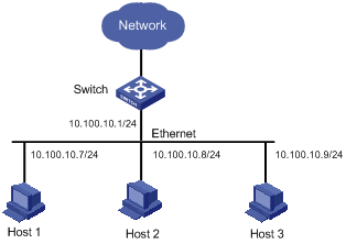
As shown in Figure 1-1, the following occasions may occur in a stable network:
l All the hosts in a network set the same gateway as their next hop, whose IP address is also known as the next hop address of the default route (for example, the next hop address of the default route is 10.100.10.1 in Figure 1-1).
l The Switch in the figure acts as the gateway of all the hosts in the network, and forwards the hosts’ packets destined for other network segments, so as to realize the communication between the hosts and the external network.
l If Switch fails, all the hosts on this segment taking Switch as the default gateway are cut off from the external network.
The networking illustrated in Figure 1-1 requires high stability of the default gateway. Normally, adding egress gateways is used to improve the system reliability. In this case, how to route between multiple egresses needs to be solved.
Virtual Router Redundancy Protocol (VRRP), an error-tolerant protocol defined in RFC 2338, well solves the problem mentioned above through separating physical devices and logical devices. In LANs with multicast or broadcast capabilities (such as Ethernet), VRRP can avoid single point failure through establishing backup links without modifying the configuration of dynamic routing protocols and router discovery protocols.
Introduction to VRRP Group
VRRP allows you to combine a group of LAN switches (including a master and several backups) into a VRRP group. The VRRP group functions as a virtual router, forwarding packets as a gateway.
Figure 1-2 VRRP network diagram
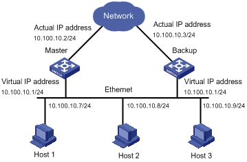
As shown in Figure 1-2, a VRRP group has the following features:
l The virtual router (the VRRP group) has its own IP address (10.100.10.1 in the above figure).
l The switches within the VRRP group must have their own IP addresses (such as 10.100.10.2 for the master and 10.100.10.3 for the backup).
l Hosts in the LAN use the IP address of the virtual router (that is, 10.100.10.1) as their default gateway.
l Hosts in the LAN only know the IP address of this virtual router, that is, 10.100.10.1, but not the specific IP addresses 10.100.10.2 of the master and 10.100.10.3 of the backup.
If the master in the VRRP group goes down, the backups in the VRRP group will reelect a master by priority. The backup with the highest priority functions as the new master to guarantee normal communication between the hosts and the external networks.
Priority of a switch in a VRRP group
You can configure the priority of a switch in a VRRP group. A master is elected from these VRRP-enabled switches by priority and the remaining switches are backups. The master in a VRRP group is the one currently with the highest priority.
Switch priority ranges from 0 to 255 (a larger number indicates a higher switch priority). Note that only 1 through 254 are available to users. Switch priorities 0 and 255 are reserved for special uses and the IP address owner respectively.
When a switch acts as the IP address owner, its priority is always 255. That is, if there is an IP address owner in a VRRP group, it acts as the master as long as it works properly.
![]()
If two switches have the same VRRP priority, the one whose VLAN interface takes effect earlier becomes the master.
Preemptive mode and preemption delay of a switch in a VRRP group
You can configure an S3600 Ethernet switch to operate in preemptive mode.
l In non-preemptive mode, as long as a switch in a VRRP group becomes the master, it stays as the master as long as it operates normally, even if a backup is assigned a higher priority later.
l If all the switches in a VRRP group are set to operate in preemptive mode, a backup sends VRRP advertisements when it finds that its priority is higher than that of the current master. In this case a new election of master is triggered, and the backup becomes the master and the former master becomes a backup accordingly.
You can also set the preemption delay for an S3600 switch.
Setting a delay period aims at:
l In an unstable network, backups in a VRRP group possibly cannot receive VRRP advertisements from the master in time due to network congestions. In this case, the backup considers itself as the master and sends out VRRP advertisements to elect master. This causes the master of the VRRP group to be determined frequently.
l With preemption delay configured, if a backup does not receive VRRP advertisements from the master in time, it waits for a while before switching to a new master. The backup does not send VRRP advertisements if it receives VRRP advertisements from the master during the specified delay period.
Authentication type and authentication key of a switch in a VRRP group
VRRP provides the following authentication types:
l simple: Simple text authentication. In a network under possible security threat, the authentication type can be set to simple. With the simple authentication type configured, the switch adds an authentication key into a VRRP packet before transmitting it. The receiver then compares the authentication key of the packet with the locally configured one. If they are the same, the packet will be taken as a true and legal one. Otherwise it will be regarded illegal and discarded.
l md5: MD5 authentication. In a vulnerable network, the authentication type can be set to md5. The switch then uses the authentication type provided in the Authentication Header and the local MD5 algorithm to authenticate the VRRP packets. Packets that fail to pass the authentication are discarded. The switch then sends trap messages to the NMS.
Virtual Router Overview
VRRP group and virtual router IP address configuration
To create a VRRP group, you need to configure an IP address for the VRRP group virtual router. The VRRP group is automatically created after you configure the first IP address for the VRRP group virtual router. Other IP addresses configured for the virtual router after this one are just added to the IP address list of the virtual router.
The virtual router IP address has the following features:
l The IP address of the virtual router can be an unassigned IP address in the network segment where a member switch of the VRRP group resides.
l You can specify the virtual router IP address as the IP address used by a member switch in the VRRP group. In this case, the member switch is called an IP address owner.
l The virtual router IP address and the IP addresses used by the member switches in the VRRP group must belong to the same network segment. If not, the VRRP group will be in the initial state (the state before you configure the VRRP on the switches of the group). In this case, VRRP does not take effect.
l A VRRP group is removed after all its virtual router IP addresses are removed. In this case, all the configurations performed for the VRRP group are disabled.
![]()
Do not configure a host IP address as the IP address of the virtual router. If your host IP address is the same as the virtual router IP address of the VRRP group, all the packets sent to the current network segment will be sent to your host. As a result, packets in the network segment cannot be forwarded properly.
Response of the virtual router to the ping operations
According to the standard VRRP, a running virtual router does not respond to the ping operations, so that you cannot use the ping command to check the network connectivity and whether the configuration of the IP address of a virtual router is successful.
For S3600 series Ethernet switches, you can specify whether the switches in a VRRP group respond to the ping operations destined for the virtual router IP addresses.
Mapping relationship between virtual router IP addresses and MAC addresses
You can set the mapping between the IP address of the virtual router and the MAC addresses of the member switches of a VRRP group, so that packets sent from the hosts in the network can be forwarded to the correct gateway according to the saved MAC address forwarding table.
There are two types of mapping between the virtual router IP address and the MAC addresses:
l Virtual router IP address-to-virtual MAC address mapping. By default, a virtual MAC address is automatically created after a virtual router IP address is configured. Hosts send packets to gateways for layer 3 forwarding according to this virtual MAC address. For S3600 series Ethernet switches, you can map multiple virtual router IP addresses of the VRRP group to one virtual MAC address.
l Virtual router IP address-to-real MAC address mapping. When there is an IP address owner in the VRRP group, a virtual router IP address may correspond to two MAC addresses, a real MAC address of the IP address owner and a virtual MAC address created by default. In this case, you can map virtual router IP addresses to the real MAC address. Then hosts send packets to the IP address owner for layer 3 forwarding according to the real MAC address.
![]()
l You need to configure the mapping between the IP addresses of the VRRP group and the MAC address before enabling VRRP feature on an S3600 Ethernet switch. If VRRP is already enabled, the system does not support this configuration.
l The number of virtual router IP addresses that can be mapped with the virtual router MAC address is determined by the chips of the switches in the VRRP group.
l A switch can belong to multiple VRRP groups. However, the number of VRRP groups supported by a switch is determined by the chip it uses. Refer to device specification for details.
VRRP Timer
There are two types of VRRP timer, the VRRP advertisement interval timer and the VRRP preemption delay timer.
VRRP advertisement interval timer
l The master advertises its normal operation state to the switches within the VRRP group by sending VRRP packets once in each specified interval (determined by the adver-interval argument).
l You can adjust the interval for a master to send VRRP advertisements by setting the VRRP advertisement interval timer. If a backup does not receive the VRRP advertisements from the master after a period three times of the specified interval, it considers itself as the master and sends out VRRP advertisements to reelect the master.
VRRP preemption delay timer
l The backup may not receive a VRRP advertisement within a period three times of the specified interval due to excessive network traffic or network instability. In this case, you can configure the VRRP preemption delay for backups.
l If you configure the preemption delay for a backup, the switch preempts the master if it does not receive a VRRP advertisement from the master after it waits for a period three times of the advertisement interval and the period specified by the preemption delay.
VRRP Tracking
![]()
l If an IP address owner exists in a VRRP group, you can configure a priority for the IP address owner. However your configuration will not take effect and the IP address owner will still be the master of the VRRP group because the system considers the priority of the IP address owner to be 255 always.
l If an IP address owner exists in a VRRP group, the interface/port tracking function configured on the IP address owner cannot take effect.
Interface tracking function of the VRRP group
When the VLAN interface of the master goes down, if you want the specified backup to become the master, you can use the interface tracking function. With this function enabled for the VRRP group:
l If the tracked VLAN interface of the master goes down, the priority of the switch decreases automatically by a specified value.
l The decrease of the master priority makes the priority of the backup tracking the interface become higher, and thus the backup becomes the new master.
Port tracking function of the VRRP group
When a physical port of the master goes down, if you want the specified backup to become the master, you can use the port tracking function. With this function enabled for the VRRP group:
l If the tracked physical port of the master goes down, the priority of the master decreases automatically by a set value.
l The decrease of the master priority makes the priority of the backup tracking the port become higher, and thus the backup becomes the new master.
Operation Procedure of VRRP
l With VRRP enabled, the switches determine their respective roles in a VRRP group by priority. The switch with the highest priority acts as the master, which will forward packets to outside networks, and the switches with lower priorities act as backups. The master sends VRRP advertisements periodically to notify that it is operating normally.
l When a backup receives a VRRP advertisement, it compares its own priority with that in the advertisement. If its priority is lower, it remains as a backup. Otherwise, it becomes the master.
l A backup starts the advertisement interval timer after it receives the advertisement to wait for the next one from the master. If the backup does not receive VRRP advertisements from the master after the timer expires, it considers that the master fails and starts the election process to elect a new master for forwarding packets.
Periodical sending of ARP packets in a VRRP Group
If a VRRP group exists on a network, the master sends gratuitous ARP packets periodically to hosts on the network, which then update their local ARP tables, ensuring that no device on this network uses the same IP address with the VRRP virtual router.
As you can create mappings between the IP address and MAC address of the VRRP virtual router, there are two cases:
l If the IP address of the virtual router corresponds to a virtual MAC address, the source MAC address in the gratuitous ARP packet will be the virtual MAC address.
l If the IP address of the virtual router corresponds to an actual MAC address, the source MAC address in the gratuitous ARP packet will be the VLAN interface’s MAC address of the master in the VRRP group.
![]()
For more information about ARP, refer to the ARP section in the part discussing ARP-MFF in this manual.
VRRP Configuration
Configuring Basic VRRP Functions
Follow these steps to configure the basic VRRP functions:
|
To do… |
Use the command… |
Remarks |
|
Enter system view |
system-view |
— |
|
Configure response of the virtual router to the ping operations |
vrrp ping-enable |
Optional By default, the virtual IP address cannot be pinged. |
|
Map the virtual router IP address to a MAC address |
vrrp method { real-mac | virtual-mac } |
Optional By default, the virtual IP address of a VRRP group is mapped to the virtual MAC address. |
|
Create a VLAN |
vlan vlan-id |
— This operation creates the VLAN to which the VRRP group corresponds. The vlan-id argument is the ID of the VLAN. |
|
Return to system view |
quit |
— |
|
Enter VLAN interface view |
interface Vlan-interface vlan-id |
— |
|
Create a VRRP group or add a virtual router IP address |
vrrp vrid virtual-router-id virtual-ip virtual-address |
Required |
|
Configure the priority of the VRRP group |
vrrp vrid virtual-router-id priority priority |
Optional 100 by default. |
![]()
It is not recommended to configure features related to VRRP group on the Layer 3 interface of a remote-probe VLAN. Otherwise, packet mirroring may be affected.
Configuring Advanced VRRP Functions
Complete these tasks to configure advanced VRRP functions
|
Task |
Remarks |
|
|
Advanced VRRP configuration |
Configuring the preemptive mode and preemption delay for a switch |
Optional |
|
Configuring VRRP authentication type and authentication key for a member switch |
Optional |
|
|
Optional |
||
|
Optional |
||
Configuring the preemptive mode and preemption delay for a switch
|
To do… |
Use the command… |
Remarks |
|
Enter system view |
system-view |
— |
|
Enter VLAN interface view |
interface Vlan-interface vlan-id |
— |
|
Configure a virtual router IP address |
vrrp vrid virtual-router-id virtual-ip virtual-address |
Required |
|
Configure the preemptive mode and preemption delay for the switches in the VRRP group |
vrrp vrid virtual-router-id preempt-mode [ timer delay delay-value ] |
Required By default, preemptive mode is set for the VRRP group and the preemption delay is 0 seconds. |
Configuring VRRP authentication type and authentication key for a member switch
|
To do… |
Use the command… |
Remarks |
|
Enter system view |
system-view |
— |
|
Enter VLAN interface view |
interface Vlan-interface vlan-id |
— |
|
Configure a virtual router IP address |
vrrp vrid virtual-router-id virtual-ip virtual-address |
Required |
|
Configure the authentication type and authentication key |
vrrp vrid virtual-router-id authentication-mode authentication-type authentication-key |
Optional No authentication is performed by default. |
Configuring VRRP timer
|
To do… |
Use the command… |
Remarks |
|
Enter system view |
system-view |
— |
|
Enter VLAN interface view |
interface Vlan-interface vlan-id |
— |
|
Configure a virtual router IP address |
vrrp vrid virtual-router-id virtual-ip virtual-address |
Required |
|
Configure the VRRP timer |
vrrp vrid virtual-router-id timer advertise adver-interval |
Optional 1 second by default. |
Configuring VRRP Tracking
Follow these steps to configure VRRP tracking:
|
To do… |
Use the command… |
Remarks |
|
Enter system view |
system-view |
— |
|
Enter VLAN interface view |
interface Vlan-interface vlan-id |
— |
|
Configure a virtual router IP address |
vrrp vrid virtual-router-id virtual-ip virtual-address |
Required |
|
Enable the interface tracking function |
vrrp vrid virtual-router-id track interface vlan-interface vlan-id [ reduced value-reduced ] |
Optional By default, the VLAN interface priority decreases by 10. |
|
Return to system view |
quit |
— |
|
Enter Ethernet port view |
interface interface-type interface-number |
— |
|
Enable the port tracking function |
vrrp vlan-interface vlan-id vrid virtual-router-id track [ reduced value-reduced ] |
Required By default, the port priority decreases by 10. |
![]()
l The port to be tracked can be in the VLAN which the VLAN interface of the VRRP group belongs to.
l Up to eight ports can be tracked simultaneously through the port tracking function.
Displaying and Maintaining VRRP
|
Use the command… |
Remarks |
|
|
Display VRRP statistics information |
display vrrp statistics [ interface vlan-interface vlan-id [ vrid virtual-router-id ] ] |
Available in any view |
|
Display VRRP state information |
display vrrp [ verbose ] [ interface vlan-interface vlan-id [ vrid virtual-router-id ] ] |
|
|
Clear VRRP statistics information |
reset vrrp statistics [ interface vlan-interface vlan-id [ vrid virtual-router-id ] ] |
Available in user view |
VRRP Configuration Examples
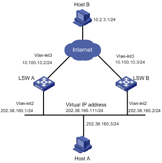
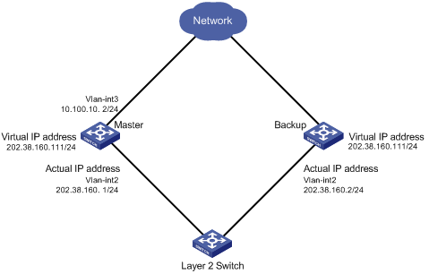
Single-VRRP Group Configuration
Network requirements
Host A uses the VRRP virtual router comprising switch A and switch B as its default gateway to visit host B on the Internet.
The information about the VRRP group is as follows:
l VRRP group ID: 1
l Virtual router IP address: 202.38.160.111/24
l Master: Switch A
l Backup: Switch B
l Preemptive mode: enabled
|
Switch |
Ethernet port connecting to Host A |
IP address of the VLAN interface |
Switch priority in the VRRP group |
|
|
LSW-A |
Ethernet 1/0/6 |
202.38.160.1/24 |
110 |
Enabled |
|
LSW-B |
Ethernet 1/0/5 |
202.38.160.2/24 |
100 (default) |
Enabled |
Network diagram
Figure 1-3 Network diagram for single-VRRP group configuration
Configuration procedure
l Configure Switch A.
# Configure VLAN 3.
<LSW-A> system-view
[LSW-A] vlan 3
[LSW-A-vlan3] port Ethernet1/0/10
[LSW-A-vlan3] quit
[LSW-A] interface Vlan-interface 3
[LSW-A-Vlan-interface3] ip address 10.100.10.2 255.255.255.0
[LSW-A-Vlan-interface3] quit
# Configure VLAN 2.
[LSW-A] vlan 2
[LSW-A-vlan2] port Ethernet 1/0/6
[LSW-A-vlan2] quit
[LSW-A] interface Vlan-interface 2
[LSW-A-Vlan-interface2] ip address 202.38.160.1 255.255.255.0
[LSW-A-Vlan-interface2] quit
# Enable a VRRP group to respond to ping operations destined for its virtual router IP address.
[LSW-A] vrrp ping-enable
# Create a VRRP group.
[LSW-A] interface Vlan-interface 2
[LSW-A-Vlan-interface2] vrrp vrid 1 virtual-ip 202.38.160.111
# Set the priority for Switch A in the VRRP group.
[LSW-A-Vlan-interface2] vrrp vrid 1 priority 110
# Configure the preemptive mode for the VRRP group.
[LSW-A-Vlan-interface2] vrrp vrid 1 preempt-mode
![]()
By default, a VRRP group adopts the preemptive mode.
l Configure Switch B.
# Configure VLAN 3.
<LSW-B> system-view
[LSW-B] vlan 3
[LSW-B-vlan3] port Ethernet1/0/10
[LSW-B-vlan3] quit
[LSW-B] interface Vlan-interface 3
[LSW-B-Vlan-interface3] ip address 10.100.10.3 255.255.255.0
[LSW-B-Vlan-interface3] quit
# Configure VLAN 2.
[LSW-B] vlan 2
[LSW-B-Vlan2] port Ethernet 1/0/5
[LSW-B-vlan2] quit
[LSW-B] interface Vlan-interface 2
[LSW-B-Vlan-interface2] ip address 202.38.160.2 255.255.255.0
[LSW-B-Vlan-interface2] quit
# Enable a VRRP group to respond to ping operations destined for its virtual router IP address.
[LSW-B] vrrp ping-enable
# Create a VRRP group.
[LSW-B] interface vlan 2
[LSW-B-Vlan-interface2] vrrp vrid 1 virtual-ip 202.38.160.111
# Configure the preemptive mode for the VRRP group.
[LSW-B-Vlan-interface2] vrrp vrid 1 preempt-mode
The IP address of the default gateway of Host A is configured as 202.38.160.111.
Normally, Switch A functions as the gateway, but when Switch A is turned off or fails, Switch B will function as the gateway instead.
Configure Switch A to operate in preemptive mode, so that it can resume its gateway function as the master after recovery.
VRRP Tracking Interface Configuration
Network requirements
Even when Switch A is still functioning, Switch B (with another link to connect with the outside) can function as a gateway when the interface on Switch A and connecting to Internet does not function properly. This can be implemented by enabling the VLAN interface tracking function.
The VRRP group ID is set to 1, with configurations of authorization key and timer.
Network diagram
Figure 1-4 Network diagram for interface tracking configuration
Configuration procedure
l Configure Switch A.
# Configure VLAN 3.
<LSW-A> system-view
[LSW-A] vlan 3
[LSW-A-vlan3] port Ethernet1/0/10
[LSW-A-vlan3] quit
[LSW-A] interface Vlan-interface 3
[LSW-A-Vlan-interface3] ip address 10.100.10.2 255.255.255.0
[LSW-A-Vlan-interface3] quit
# Configure VLAN 2.
[LSW-A] vlan 2
[LSW-A-vlan2] port Ethernet 1/0/6
[LSW-A-vlan2] quit
[LSW-A] interface Vlan-interface 2
[LSW-A-Vlan-interface2] ip address 202.38.160.1 255.255.255.0
[LSW-A-Vlan-interface2] quit
# Configure that the virtual router can be pinged.
[LSW-A] vrrp ping-enable
# Create a VRRP group.
[LSW-A] interface Vlan-interface 2
[LSW-A-Vlan-interface2] vrrp vrid 1 virtual-ip 202.38.160.111
# Set the priority for the VRRP group.
[LSW-A-Vlan-interface2] vrrp vrid 1 priority 110
# Set the authentication type for the VRRP group to md5, and the password to abc123.
[LSW-A-Vlan-interface2] vrrp vrid 1 authentication-mode md5 abc123
# Configure the master to send VRRP packets every 5 seconds.
[LSW-A-Vlan-interface2] vrrp vrid 1 timer advertise 5
# Set the tracked VLAN interface.
[LSW-A-Vlan-interface2] vrrp vrid 1 track interface Vlan-interface 3 reduced 30
l Configure switch B.
# Configure VLAN 3.
<LSW-B> system-view
[LSW-B] vlan 3
[LSW-B-vlan3] port Ethernet1/0/10
[LSW-B-vlan3] quit
[LSW-B] interface Vlan-interface 3
[LSW-B-Vlan-interface3] ip address 10.100.10.3 255.255.255.0
[LSW-B-Vlan-interface3] quit
# Configure VLAN 2.
[LSW-B] vlan 2
[LSW-B-vlan2] port Ethernet 1/0/5
[LSW-B-vlan2] quit
[LSW-B] interface Vlan-interface 2
[LSW-B-Vlan-interface2] ip address 202.38.160.2 255.255.255.0
[LSW-B-Vlan-interface2] quit
# Configure that the virtual router can be pinged through.
[LSW-B] vrrp ping-enable
# Create a VRRP group.
[LSW-B] interface Vlan-interface 2
[LSW-B-Vlan-interface2] vrrp vrid 1 virtual-ip 202.38.160.111
# Configure the authentication key for the VRRP group.
[LSW-B-Vlan-interface2] vrrp vrid 1 authentication-mode md5 abc123
# Configure the master to send VRRP packets every 5 seconds.
[LSW-B-Vlan-interface2] vrrp vrid 1 timer advertise 5
Normally, Switch A functions as the gateway, but when VLAN-interface 3 on Switch A goes down, its priority will be reduced by 30, lower than that of Switch B so that Switch B will preempt the master for gateway services instead.
When VLAN-interface 3 recovers, switch A will resume its gateway function as the master.
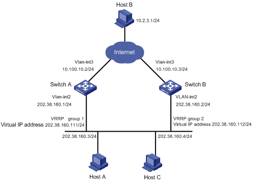
Multiple-VRRP Group Configuration
Network requirements
A switch can function as a backup of multiple VRRP groups.
Multiple-VRRP group configuration can implement load balancing. For example, Switch A acts as the master of VRRP group 1 and a backup in VRRP group 2. Similarly, Switch B acts as the master of VRRP group 2 and a backup in VRRP group 1. Some hosts in the network take virtual router 1 as the gateway, while others take virtual router 2 as the gateway. In this way, both load balancing and mutual backup are implemented.
Network diagram
Figure 1-5 Network diagram for multiple-VRRP group configuration
Configuration procedure
l Configure Switch A.
# Configure VLAN 3.
<LSW-A> system-view
[LSW-A] vlan 3
[LSW-A-vlan3] port Ethernet1/0/10
[LSW-A-vlan3] quit
[LSW-A] interface Vlan-interface 3
[LSW-A-Vlan-interface3] ip address 10.100.10.2 255.255.255.0
[LSW-A-Vlan-interface3] quit
# Configure VLAN 2.
[LSW-A] vlan 2
[LSW-A-vlan2] port Ethernet 1/0/6
[LSW-A-vlan2] quit
[LSW-A] interface Vlan-interface 2
[LSW-A-Vlan-interface2] ip address 202.38.160.1 255.255.255.0
# Create VRRP group 1.
[LSW-A-Vlan-interface2] vrrp vrid 1 virtual-ip 202.38.160.111
# Set the priority for VRRP group 1.
[LSW-A-Vlan-interface2] vrrp vrid 1 priority 150
# Create VRRP group 2.
[LSW-A-Vlan-interface2] vrrp vrid 2 virtual-ip 202.38.160.112
l Configure Switch B.
# Configure VLAN 3.
<LSW-B> system-view
[LSW-B] vlan 3
[LSW-B-vlan3] port Ethernet1/0/10
[LSW-B-vlan3] quit
[LSW-B] interface Vlan-interface 3
[LSW-B-Vlan-interface3] ip address 10.100.10.3 255.255.255.0
[LSW-B-Vlan-interface3] quit
# Configure VLAN 2.
[LSW-B] vlan 2
[LSW-B-vlan2] port Ethernet 1/0/6
[LSW-B-vlan2] quit
[LSW-B] interface Vlan-interface 2
[LSW-B-Vlan-interface2] ip address 202.38.160.2 255.255.255.0
# Create VRRP group 1.
[LSW-B-Vlan-interface2] vrrp vrid 1 virtual-ip 202.38.160.111
# Create VRRP group 2.
[LSW-B-Vlan-interface2] vrrp vrid 2 virtual-ip 202.38.160.112
# Set the priority for VRRP group 2.
[LSW-B-Vlan-interface2] vrrp vrid 2 priority 110
![]()
Normally, multiple VRRP groups are used in actual use.
Port Tracking Configuration Examples
Network requirements
l VRRP group 1 comprises two switches, which act as the master and the backup.
l The actual IP addresses of the master and the backups are 10.100.10.2 and 10.100.10.3 respectively.
l The master is connected to the upstream network through its Ethernet 1/0/1 port. The backup is connected to the upstream network through its Ethernet 1/0/2 port.
l The virtual router IP address of the VRRP group is 10.100.10.1.
l Enable the port tracking function on Ethernet 1/0/1 port of the master and specify that the priority of the master decreases by 50 when Ethernet 1/0/1 port fails, which triggers new master being determined in the VRRP group 1.
Network diagram
Figure 1-6 Network diagram for VRRP port tracking configuration
Configuration procedure
l Configure the master switch.
# Enter system view.
<Sysname> system-view
# Create VLAN 3.
[Sysname] vlan 3
[Sysname-vlan3] port Ethernet1/0/1
[Sysname-vlan3] quit
# Configure VLAN-interface 3.
[Sysname] interface Vlan-interface 3
[Sysname-Vlan-interface3] ip address 10.100.10.2 255.255.255.0
[Sysname-Vlan-interface3] quit
# Create VLAN 2.
[Sysname] vlan 2
[Sysname-vlan2] port Ethernet1/0/2
[Sysname-vlan2] quit
# Configure VLAN-interface 2.
[Sysname] interface Vlan-interface 2
[Sysname-Vlan-interface2] ip address 202.38.160.1 255.255.255.0
[Sysname-Vlan-interface2] quit
# Create a VRRP group.
[Sysname] interface Vlan-interface 2
[Sysname-Vlan-interface2] vrrp vrid 1 virtual-ip 202.38.160.111
# Enter Ethernet 1/0/1 port view and enable the VRRP tracking function.
[Sysname] interface Ethernet1/0/1
[Sysname-Ethernet1/0/1] vrrp Vlan-interface 2 vrid 1 track reduced 50
Troubleshooting VRRP
You can locate VRRP problems through the configuration and debugging information. Here are some possible symptoms you might meet and the corresponding troubleshooting methods.
Symptom 1: Frequent prompts of configuration errors on the console
This indicates that incorrect VRRP packets are received. It may be because of the inconsistent configuration of the switches within the VRRP group, or the attempt of other devices sending illegal VRRP packets.
l The first possible fault can be solved through modifying the configuration.
l The second possibility is caused by the malicious attempt of some devices; non-technical measures should be taken to solve the problem.
Symptom 2: More than one master existing within a VRRP group
There are also 2 reasons. One is short coexistence of many masters, which is normal and needs no manual intervention. Another is long coexistence of many masters, which may be caused because the original master and other member switches in a VRRP group cannot receive VRRP packets from each other, or receive some illegal packets.
To solve such a problem:
l An attempt should be made to ping among these masters.
l If such an attempt fails, check the connectivity between related devices.
l If they can be pinged, check VRRP configuration.
l For the configuration of a VRRP group, complete consistency for the number of virtual IP addresses, each virtual IP address, timer interval and authentication type configured on each member switch must be guaranteed.
Symptom 3: VRRP state of a switch changing repeatedly
Such problems occur when the VRRP group timer interval is too short. They can be solved through prolonging the interval or configuring the preemption delay period.