- Table of Contents
-
- H3C S3600 Operation Manual-Release 1602(V1.02)
- 00-1Cover
- 00-2Product Overview
- 01-CLI Operation
- 02-Login Operation
- 03-Configuration File Management Operation
- 04-VLAN Operation
- 05-IP Address and Performance Operation
- 06-Voice VLAN Operation
- 07-GVRP Operation
- 08-Port Basic Configuration Operation
- 09-Link Aggregation Operation
- 10-Port Isolation Operation
- 11-Port Security-Port Binding Operation
- 12-DLDP Operation
- 13-MAC Address Table Management Operation
- 14-Auto Detect Operation
- 15-MSTP Operation
- 16-Routing Protocol Operation
- 17-Multicast Operation
- 18-802.1x and System Guard Operation
- 19-AAA Operation
- 20-Web Authentication Operation
- 21-MAC Address Authentication Operation
- 22-VRRP Operation
- 23-ARP Operation
- 24-DHCP Operation
- 25-ACL Operation
- 26-QoS-QoS Profile Operation
- 27-Web Cache Redirection Operation
- 28-Mirroring Operation
- 29-IRF Fabric Operation
- 30-Cluster Operation
- 31-PoE-PoE Profile Operation
- 32-UDP Helper Operation
- 33-SNMP-RMON Operation
- 34-NTP Operation
- 35-SSH Operation
- 36-File System Management Operation
- 37-FTP-SFTP-TFTP Operation
- 38-Information Center Operation
- 39-System Maintenance and Debugging Operation
- 40-VLAN-VPN Operation
- 41-HWPing Operation
- 42-IPv6 Management Operation
- 43-DNS Operation
- 44-Smart Link-Monitor Link Operation
- 45-Access Management Operation
- 46-Appendix
- Related Documents
-
| Title | Size | Download |
|---|---|---|
| 23-ARP Operation | 241.04 KB |
Table of Contents
Introduction to ARP Attack Detection
Introduction to ARP Packet Rate Limit
Introduction to Gratuitous ARP
Configuring ARP Basic Functions
Configuring ARP Attack Detection
Configuring the ARP Packet Rate Limit Function
ARP Basic Configuration Example
ARP Attack Detection and Packet Rate Limit Configuration Example
Proxy ARP Configuration Examples
Proxy ARP Configuration Example
Proxy ARP Configuration in Port Isolation Application
Resilient ARP Configuration Example
When configuring ARP, go to these sections for information you are interested in:
l Displaying and Debugging ARP
![]()
l The ARP attack detection feature is added to this manual. For details, refer to section Introduction to ARP Attack Detection.
l The ARP packet rate limit feature is added to the manual. For details, refer to section Introduction to ARP Packet Rate Limit.
l The periodical sending of gratuitous ARP packets feature is added. For details, refer to section Periodical sending of gratuitous ARP packets and Periodical sending of ARP packets in a VRRP backup group.
l The proxy ARP feature is added. For details, refer to Proxy ARP Configuration.
Introduction to ARP
ARP Function
Address Resolution Protocol (ARP) is used to resolve an IP address into a data link layer address.
An IP address is the address of a host at the network layer. To send a network layer packet to a destination host, the device must know the data link layer address (MAC address, for example) of the destination host or the next hop. To this end, the IP address must be resolved into the corresponding data link layer address.
![]()
Unless otherwise stated, a data link layer address in this chapter refers to a 48-bit Ethernet MAC address.
ARP Message Format
ARP messages are classified as ARP request messages and ARP reply messages. Figure 1-1 illustrates the format of these two types of ARP messages.
l As for an ARP request, all the fields except the hardware address of the receiver field are set. The hardware address of the receiver is what the sender requests for.
l As for an ARP reply, all the fields are set.
Figure 1-1 ARP message format
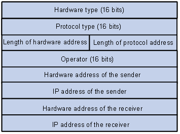
Table 1-1 describes the fields of an ARP packet.
Table 1-1 Description on the fields of an ARP packet
|
Field |
Description |
|
Hardware Type |
Type of the hardware interface. Refer to Table 1-2 for the information about the field values. |
|
Protocol type |
Type of protocol address to be mapped. 0x0800 indicates an IP address. |
|
Length of hardware address |
Hardware address length (in bytes) |
|
Length of protocol address |
Protocol address length (in bytes) |
|
Operator |
Indicates the type of a data packets, which can be: l 1: ARP request packets l 2: ARP reply packets l 3: RARP request packets l 4: RARP reply packets |
|
Hardware address of the sender |
Hardware address of the sender |
|
IP address of the sender |
IP address of the sender |
|
Hardware address of the receiver |
l For an ARP request packet, this field is null. l For an ARP reply packet, this field carries the hardware address of the receiver. |
|
IP address of the receiver |
IP address of the receiver |
Table 1-2 Description on the values of the hardware type field
|
Value |
Description |
|
1 |
Ethernet |
|
2 |
Experimental Ethernet |
|
3 |
X.25 |
|
4 |
Proteon ProNET (Token Ring) |
|
5 |
Chaos |
|
6 |
IEEE802.X |
|
7 |
ARC network |
ARP Table
In an Ethernet, the MAC addresses of two hosts must be available for the two hosts to communicate with each other. Each host in an Ethernet maintains an ARP table, where the latest used IP address-to-MAC address mapping entries are stored. S3600 series Ethernet switches provide the display arp command to display the information about ARP mapping entries.
ARP entries in an S3600 series Ethernet switch can either be static entries or dynamic entries, as described in Table 1-3.
|
ARP entry |
Generation Method |
Maintenance Mode |
|
Static ARP entry |
Manually configured |
Manual maintenance |
|
Dynamic ARP entry |
Dynamically generated |
ARP entries of this type age with time. The aging period is set by the ARP aging timer. |
ARP Process
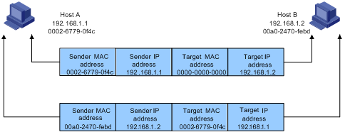
Suppose that Host A and Host B are on the same subnet and that Host A sends a message to Host B. The resolution process is as follows:
1) Host A looks in its ARP mapping table to see whether there is an ARP entry for Host B. If Host A finds it, Host A uses the MAC address in the entry to encapsulate the IP packet into a data link layer frame and sends the frame to Host B.
2) If Host A finds no entry for Host B, Host A buffers the packet and broadcasts an ARP request, in which the source IP address and source MAC address are respectively the IP address and MAC address of Host A and the destination IP address and MAC address are respectively the IP address of Host B and an all-zero MAC address. Because the ARP request is sent in broadcast mode, all hosts on this subnet can receive the request, but only the requested host (namely, Host B) will process the request.
3) Host B compares its own IP address with the destination IP address in the ARP request. If they are the same, Host B saves the source IP address and source MAC address into its ARP mapping table, encapsulates its MAC address into an ARP reply, and unicasts the reply to Host A.
4) After receiving the ARP reply, Host A adds the MAC address of Host B into its ARP mapping table for subsequent packet forwarding. Meanwhile, Host A encapsulates the IP packet and sends it out.
Usually ARP dynamically implements and automatically seeks mappings from IP addresses to MAC addresses, without manual intervention.
Introduction to ARP Attack Detection
Man-in-the-middle attack
According to the ARP design, after receiving an ARP response, a host adds the IP-to-MAC mapping of the sender into its ARP mapping table even if the MAC address is not the real one. This can reduce the ARP traffic in the network, but it also makes ARP spoofing possible.
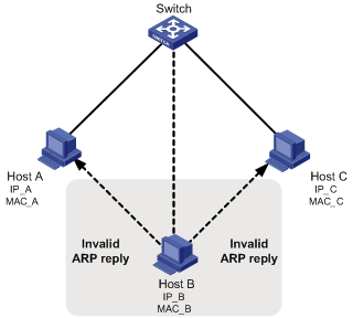
In Figure 1-3, Host A communicates with Host C through a switch. To intercept the traffic between Host A and Host C, the hacker (Host B) forwards invalid ARP reply messages to Host A and Host C respectively, causing the two hosts to update the MAC address corresponding to the peer IP address in their ARP tables with the MAC address of Host B. Then, the traffic between Host A and C will pass through Host B which acts like a “man-in-the-middle” that may intercept and modify the communication information. Such an attack is called man-in-the-middle attack.
Figure 1-3 Network diagram for ARP man-in-the-middle attack
ARP attack detection
To guard against the man-in-the-middle attacks launched by hackers or attackers, S3600 series Ethernet switches support the ARP attack detection function. All ARP (both request and response) packets passing through the switch are redirected to the CPU, which checks the validity of all the ARP packets by using the DHCP snooping table or the manually configured IP binding table. For description of DHCP snooping table and the manually configured IP binding table, refer to the DHCP snooping section in the part discussing DHCP in this manual.
After you enable the ARP attack detection function, the switch will check the following items of an ARP packet: the source MAC address, source IP address, port number of the port receiving the ARP packet, and the ID of the VLAN the port resides. If these items match the entries of the DHCP snooping table or the manual configured IP binding table, the switch will forward the ARP packet; if not, the switch discards the ARP packet.
l With trusted ports configured, ARP packets coming from the trusted ports will not be checked, while those from other ports will be checked through the DHCP snooping table or the manually configured IP binding table.
l With the ARP restricted forwarding function enabled, ARP request packets are forwarded through trusted ports only; ARP response packets are forwarded according to the MAC addresses in the packets, or through trusted ports if the MAC address table contains no such destination MAC addresses.
Introduction to ARP Packet Rate Limit
With this function enabled on a port, the switch will count the ARP packets received on the port within each second. If the number of ARP packets received on the port per second exceeds the preconfigured value, the switch considers that the port is attacked by ARP packets. In this case, the switch will shut down the port. As the port does not receive any packet, the switch is protected from the ARP packet attack.
At the same time, the switch supports automatic recovery of port state. If a port is shut down by the switch due to high packet rate, the port will revert to the Up state after a configured period of time.
Introduction to Gratuitous ARP
The following are the characteristics of gratuitous ARP packets:
l Both source and destination IP addresses carried in a gratuitous ARP packet are the local addresses, and the source MAC address carried in it is the local MAC addresses.
l If a device finds that the IP addresses carried in a received gratuitous packet conflict with those of its own, it returns an ARP response to the sending device to notify of the IP address conflict.
By sending gratuitous ARP packets, a network device can:
l Determine whether or not IP address conflicts exist between it and other network devices.
l Trigger other network devices to update its hardware address stored in their caches.
With the gratuitous ARP packet learning function enabled:
A device receiving a gratuitous ARP packet adds the information carried in the packet to its own dynamic ARP table if it finds no corresponding ARP entry for the ARP packet exists in the cache.
Periodical sending of gratuitous ARP packets
In an actual network, when the network load or the CPU occupancy of the receiving host is high, ARP packets may be lost or the host may be unable to timely process the ARP packets received. In such a case, the dynamic ARP entries on the receiving host may age out, and the traffic between the host and the sending device will get interrupted before the host learns the MAC address of the sending device again and installs a corresponding entry in the ARP table.
To address this issue, by default, the S3600 series allow VLAN interfaces to send gratuitous ARP packets periodically. That is, as long as a VLAN interface is in the Up state, it sends gratuitous ARP packets at an interval of 30 seconds so that the receiving host can refresh the MAC address of the switch in the ARP table timely, thereby preventing traffic interruption mentioned above.
Periodical sending of ARP packets in a VRRP backup group
If a VRRP backup group exists on a network, the master switch sends gratuitous ARP packets periodically to hosts on the network, which then update their local ARP tables, ensuring that no device on this network uses the same IP address with the VRRP virtual router.
As you can create mappings between the IP address and MAC address of the VRRP virtual router, there are two cases:
l If the IP address of the virtual router corresponds to a virtual MAC address, the source MAC address in the gratuitous ARP packet will be the virtual MAC address.
l If the IP address of the virtual router corresponds to an actual MAC address, the source MAC address in the gratuitous ARP packet will be the VLAN interface’s MAC address of the master switch in the VRRP backup group.
Configuring ARP
Configuring ARP Basic Functions
Follow these steps to configure ARP basic functions:
|
To do… |
Use the command… |
Remarks |
|
Enter system view |
system-view |
— |
|
Add a static ARP entry |
arp static ip-address mac-address [ vlan-id interface-type interface-number ] |
Optional By default, the ARP mapping table is empty, and entries are created dynamically by ARP. |
|
Configure the ARP aging timer |
arp timer aging aging-time |
Optional 20 minutes by default. |
|
Enable the ARP entry checking function (that is, disable the switch from learning ARP entries with multicast MAC addresses) |
arp check enable |
Optional Enabled by default. |
![]()
l Static ARP entries are valid as long as the Ethernet switch operates normally. But some operations, such as removing a VLAN, or removing a port from a VLAN, will make the corresponding ARP entries invalid and therefore removed automatically.
l As for the arp static command, the value of the vlan-id argument must be the ID of an existing VLAN, and the port identified by the interface-type and interface-number arguments must belong to the VLAN.
l Currently, static ARP entries cannot be configured on the ports of an aggregation group.
Configuring ARP Attack Detection
Follow these steps to configure the ARP attack detection function:
|
To do… |
Use the command… |
Remarks |
|
Enter system view |
system-view |
— |
|
Enable DHCP snooping |
dhcp-snooping |
Required Disabled by default. |
|
Enter Ethernet port view |
interface interface-type interface-number |
— |
|
Specify the current port as a trusted port |
dhcp-snooping trust |
Required By default, after DHCP snooping is enabled, all ports of a switch are untrusted ports. |
|
Quit to system view |
quit |
— |
|
Enter VLAN view |
vlan vlan-id |
— |
|
Enable the ARP attack detection function |
arp detection enable |
Required By default, ARP attack detection is disabled on all ports. |
|
Quit to system view |
quit |
— |
|
Enter Ethernet port view |
interface interface-type interface-number |
— |
|
Configure the port as an ARP trusted port |
arp detection trust |
Optional By default, a port is an untrusted port. |
|
Quit to system view |
quit |
— |
|
Enter VLAN view |
vlan vlan-id |
— |
|
Enable ARP restricted forwarding |
arp restricted-forwarding enable |
Optional Disabled by default. The device forwards legal ARP packets through all its ports. |
![]()
l You need to enable DHCP snooping and configure DHCP snooping trusted ports on the switch before configuring the ARP attack detection function. For more information about DHCP snooping, refer to DHCP Operation in this manual.
l Currently, the VLAN ID of an IP-to-MAC binding configured on a port of an S3600 series Ethernet switch is the same as the default VLAN ID of the port. If the VLAN tag of an ARP packet is different from the default VLAN ID of the receiving port, the ARP packet cannot pass the ARP attack detection based on the IP-to-MAC bindings.
l Generally, the uplink port of a switch is configured as a trusted port.
l Before enabling ARP restricted forwarding, make sure you have enabled ARP attack detection and configured ARP trusted ports.
l You are not recommended to configure ARP attack detection on the ports of a fabric or an aggregation group.
Configuring the ARP Packet Rate Limit Function
Follow these steps to configure the ARP packet rate limit function:
|
To do… |
Use the command… |
Remarks |
|
Enter system view |
system-view |
— |
|
Enter Ethernet port view |
interface interface-type interface-number |
— |
|
Enable the ARP packet rate limit function |
arp rate-limit enable |
Required By default, the ARP packet rate limit function is disabled on a port. |
|
Configure the maximum ARP packet rate allowed on the port |
arp rate-limit rate |
Optional By default, the maximum ARP packet rate allowed on a port is 15 pps. |
|
Quit to system view |
quit |
— |
|
Enable the port state auto-recovery function |
arp protective-down recover enable |
Optional Disabled by default. |
|
Configure the port state auto-recovery interval |
arp protective-down recover interval interval |
Optional By default, when the port state auto-recovery function is enabled, the port state auto-recovery interval is 300 seconds. |
![]()
l You need to enable the port state auto-recovery feature before you can configure the port state auto-recovery interval.
l You are not recommended to configure the ARP packet rate limit function on the ports of a fabric or an aggregation group.
Configuring Gratuitous ARP
Follow these steps to configure gratuitous ARP:
|
Use the command… |
Remarks |
|
|
Enter system view |
system-view |
— |
|
Enable the gratuitous ARP packet learning function |
gratuitous-arp-learning enable |
Optional Enabled by default. |
|
Enable the master switch of a VRRP backup group to send gratuitous ARP packets periodically |
arp send-gratuitous enable vrrp |
Optional Disabled by default. Among S3600 series Ethernet switches, only S3600-EI series switches support this command. |
|
Enter VLAN interface view |
interface Vlan-interface vlan-id |
— |
|
Enable the VLAN interface to send gratuitous ARP packets periodically |
gratuitous-arp period-sending enable |
Optional Enabled by default. |
![]()
l The sending of gratuitous ARP packets is enabled as long as an S3600 switch operates. No command is needed for enabling this function. That is, the device sends gratuitous ARP packets whenever a VLAN interface is enabled (such as when a link is enabled or an IP address is configured for the VLAN interface) or whenever the IP address of a VLAN interface is changed.
l As for S3600-EI series Ethernet switches, before enabling the master switch of a VRRP backup group to send gratuitous ARP packets periodically, you need to create the VRRP backup group and perform corresponding configurations. Refer to the part discussing VRRP in this manual for details.
Displaying and Debugging ARP
|
To do… |
Use the command… |
Remarks |
|
Display specific ARP mapping table entries |
display arp [ static | dynamic | ip-address ] |
Available in any view |
|
Display the ARP mapping entries related to a specified string in a specified way |
display arp [ dynamic | static ] | { begin | include | exclude } regular-expression |
|
|
Display the number of the ARP entries of a specified type |
display arp count [ [ dynamic | static ] [ | { begin | include | exclude } regular-expression ] | ip-address ] |
|
|
Display the statistics about the untrusted ARP packets dropped by the specified port |
display arp detection statistics interface interface-type interface-number |
|
|
Display the setting of the ARP aging timer |
display arp timer aging |
|
|
Clear specific ARP entries |
reset arp [ dynamic | static | interface interface-type interface-number ] |
Available in user view |
ARP Configuration Examples
ARP Basic Configuration Example
Network requirements
l Disable ARP entry check on the switch.
l Disable VLAN-interface 1 of the switch from sending gratuitous ARP packets periodically.
l Set the aging time for dynamic ARP entries to 10 minutes.
l Add a static ARP entry, with the IP address being 192.168.1.1, the MAC address being 000f-e201-0000, and the outbound port being Ethernet 1/0/10 of VLAN 1.
Configuration procedure
<Sysname> system-view
[Sysname] undo arp check enable
[Sysname] interface vlan 1
[Sysname-Vlan-interface1] undo gratuitous-arp period-resending enable
[Sysname-Vlan-interface1] quit
[Sysname] arp timer aging 10
[Sysname] arp static 192.168.1.1 000f-e201-0000 1 Ethernet1/0/10
ARP Attack Detection and Packet Rate Limit Configuration Example
Network requirements
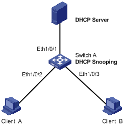
As shown in Figure 1-4, Ethernet 1/0/1 of Switch A connects to DHCP Server; Ethernet 1/0/2 connects to Client A, Ethernet 1/0/3 connects to Client B. Ethernet 1/0/1, Ethernet 1/0/2 and Ethernet 1/0/3 belong to VLAN 1.
l Enable DHCP snooping on Switch A and specify Ethernet 1/0/1 as the DHCP snooping trusted port.
l Enable ARP attack detection in VLAN 1 to prevent ARP man-in-the-middle attacks, and specify Ethernet 1/0/1 as the ARP trusted port.
l Enable the ARP packet rate limit function on Ethernet 1/0/2 and Ethernet 1/0/3 of Switch A, so as to prevent Client A and Client B from attacking Switch A through ARP traffic.
l Enable the port state auto recovery function on the ports of Switch A, and set the recovery interval to 200 seconds.
Network diagram
Figure 1-4 ARP attack detection and packet rate limit configuration
Configuration procedure
# Enable DHCP snooping on Switch A.
<SwitchA> system-view
[SwitchA] dhcp-snooping
# Specify Ethernet 1/0/1 as the DHCP snooping trusted port and the ARP trusted port.
[SwitchA] interface Ethernet1/0/1
[SwitchA-Ethernet1/0/1] dhcp-snooping trust
[SwitchA-Ethernet1/0/1] arp detection trust
[SwitchA-Ethernet1/0/1] quit
# Enable ARP attack detection on all ports in VLAN 1.
[SwitchA] vlan 1
[SwitchA-vlan1] arp detection enable
# Enable the ARP packet rate limit function on Ethernet 1/0/2, and set the maximum ARP packet rate allowed on the port to 20 pps.
[SwitchA] interface Ethernet1/0/2
[SwitchA-Ethernet1/0/2] arp rate-limit enable
[SwitchA-Ethernet1/0/2] arp rate-limit 20
[SwitchA-Ethernet1/0/2] quit
# Enable the ARP packet rate limit function on Ethernet 1/0/3, and set the maximum ARP packet rate allowed on the port to 50 pps.
[SwitchA] interface Ethernet1/0/3
[SwitchA-Ethernet1/0/3] arp rate-limit enable
[SwitchA-Ethernet1/0/3] arp rate-limit 50
[SwitchA-Ethernet1/0/3] quit
# Configure the port state auto recovery function, and set the recovery interval to 200 seconds.
[SwitchA] arp protective-down recover enable
[SwitchA] arp protective-down recover interval 200
When configuring proxy ARP, go to these sections for information you are interested in:
l Proxy ARP Configuration Examples
Proxy ARP Overview
Introduction to Proxy ARP
With the proxy ARP feature enabled on the switch, hosts on the same network segment but different physical networks appear as if they on the same physical network to users.
Work Mechanism of Proxy ARP
Figure 2-1 Work mechanism of proxy ARP
As shown in Figure 2-1:
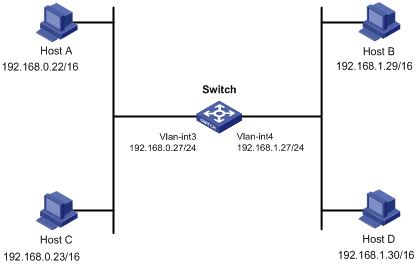
Host A and Host D are on different sub networks. When Host A (192.168.0.22/16) needs to send packets to Host D (192.168.1.30/16), because the mask of the two hosts are both 16 bits, Host A regards Host D to be on its directly connected sub network, and thus Host A will broadcast an ARP request to request the MAC address of Host D.
l When the proxy ARP feature is not enabled on the switch, because Host A and Host D are in different VLANs, the ARP request sent by Host A cannot reach Host D, and the two hosts cannot communicate.
l With proxy ARP enabled on the switch, when VLAN-interface 3 receives the ARP request, if the switch finds a route to the destination IP address (encapsulated in the ARP request) in the routing table, the switch sends host A the MAC address of VLAN-interface 3 in an ARP response (with the source IP address being the destination IP address of the ARP request). After receiving the ARP response, Host A creates an ARP entry, in which the destination IP address is the IP address of Host D (192.168.1.30/16), and the MAC address is that of VLAN-interface 3. The following packets sent from Host A to Host D will all be sent to VLAN-interface 3 of the switch, and then the switch forwards the packets in Layer 3 to Host D, so as to realize the Layer 3 connectivity between Host A and Host D.
Configuring Proxy ARP
Follow these steps to configure proxy ARP:
|
To do… |
Use the command… |
Remarks |
|
Enter system view |
system-view |
— |
|
Enter VLAN interface view |
interface Vlan-interface vlan-id |
— |
|
Enable proxy ARP |
arp proxy enable |
Required Disabled by default. |
|
Display the proxy ARP configuration |
display arp proxy [ interface Vlan-interface vlan-id ] |
Available in any view |
Proxy ARP Configuration Examples
Proxy ARP Configuration Example
Network requirements
l The IP address of Host A is 192.168.0.22/16, and that of Host D is 192.168.1.30/16.
l Create VLAN 3 and VLAN 4 on the switch.
l The IP address of VLAN-interface 3 is 192.168.0.27/24, and that of VLAN-interface 4 is 192.168.1.27/24.
Network diagram
Figure 2-2 Network diagram for proxy ARP
Configuration procedure
# Configure the IP address of VLAN-interface 3 to be 192.168.0.27/24.
<Switch> system-view
[Switch] interface Vlan-interface 3
[Switch-Vlan-interface3] ip address 192.168.0.27 24
[Switch-Vlan-interface3] quit
# Configure the IP address of VLAN-interface 4 to be 192.168.1.27/24.
[Switch] interface Vlan-interface 4
[Switch-Vlan-interface4] ip address 192.168.1.27 24
[Switch-Vlan-interface4] quit
# Enter VLAN-interface 3 view, and enable proxy ARP on it.
[Switch] interface Vlan-interface 3
[Switch-Vlan-interface3] arp proxy enable
[Switch-Vlan-interface3] quit
# Enter VLAN-interface 4 view, and enable proxy ARP on it.
[Switch] interface Vlan-interface 4
[Switch-Vlan-interface4] arp proxy enable
[Switch-Vlan-interface4] quit
Proxy ARP Configuration in Port Isolation Application
Network requirements
l Switch A (a S3600 series Ethernet switch) is connected to Switch B through Ethernet 1/0/1.
l Ethernet 1/0/2 and Ethernet 1/0/3 on Switch B belong to VLAN 1, and are connected to Host A and Host B respectively.
l Host A and Host B isolated at Layer 2 can communicate at Layer 3 through Switch A.
Network diagram
Figure 2-3 Network diagram for Proxy ARP configuration in port isolation application
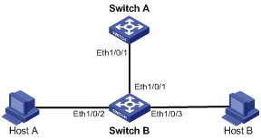
Configuration procedure
1) Configure Switch B
# Add Ethernet 1/0/2 and Ethernet 1/0/3 into an isolation group, disabling Host A and Host B from communicating with each other at Layer 2.
For details about port isolation, refer to the part discussing port isolation.
<SwitchB> system-view
[SwitchB] interface Ethernet1/0/2
[SwitchB-Ethernet1/0/2] port isolate
[SwitchB-Ethernet1/0/2] quit
[SwitchB] interface Ethernet1/0/3
[SwitchB-Ethernet1/0/3] port isolate
[SwitchB-Ethernet1/0/3] quit
2) Configure Switch A
# Configure proxy ARP on VLAN-interface 1, enabling Host A and Host B to communicate at Layer 3.
<SwitchA> system-view
[SwitchA] interface Vlan-interface 1
[SwitchA-Vlan-interface1] arp proxy enable
[SwitchA-Vlan-interface1] quit
When configuring resilient ARP, go to these sections for information you are interested in:
l Introduction to Resilient ARP
l Resilient ARP Configuration Example
![]()
The features in this chapter apply to S3600-EI series switches only.
Introduction to Resilient ARP
In intelligent resilient framework (IRF) network application, normally you need to connect redundancy links between the fabric and other devices to support the resilient network. But if the connections inside the fabric break off, the fabric splits. In this case, the redundancy link may connect with two or more Layer 3 devices with the same configurations in the same network. Thus these devices operate the same routing function. Adopting the Resilient ARP function can avoid this. Resilient ARP can find whether there are the same Layer 3 devices in the network. If so, it keeps one device as the Layer 3 device, and changes the other devices to be the Layer 2 devices.
The state machine of Resilient ARP has six states which are Initialize, LisentForL3Master, L3Master, L3slave, L2Master, and L2slave. L3Master sends Resilient ARP packets periodically to notify other fabrics that the local fabric is in the Layer 3 state.
Resilient ARP implements the system state switching by sending/receiving Resilient ARP packets periodically, so as to determine a device to work as a Layer 3 device or a Layer 2 device.
Configuring Resilient ARP
Resilient ARP configuration includes:
l Enable/disable the Resilient ARP function.
When Resilient ARP function is enabled, the system can deal with the devices according to the current state. When the connections inside a fabric break off, Resilient ARP can send Resilient ARP packets through the VLAN interface where the redundancy link resides, so as to determine a device to work as a Layer 3 device or as a Layer 2 device.
l Configure the VLAN interface through which Resilient packets are sent.
You can use the following commands to configure the VLAN interface through which Resilient packets are sent. When no VLAN interface is specified, Resilient packets are sent through the default VLAN interface.
Follow these steps to configure the Resilient ARP function:
|
To do… |
Use the command… |
Remarks |
|
Enter system view |
system-view |
— |
|
Enable the Resilient ARP function |
resilient-arp enable |
Required Enabled by default. |
|
Configure the VLAN interface through which Resilient packets are sent |
resilient-arp interface vlan-interface vlan-id |
Optional By default, Resilient ARP packets are sent through the interface of VLAN 1 (VLAN-interface 1). |
|
Display information about the Resilient ARP state |
display resilient-arp [ unit unit-id ] |
Available in any view |
Note that the above configuration specifies the VLAN interface through which Resilient packets are sent, whereas all the VLAN interfaces can receive Resilient ARP packets.
Resilient ARP Configuration Example
Network requirements
There are four units in an IRF network: unit 1 to unit 4. Unit 1 and unit 3 connect to another switch (Switch) through link aggregation. If the connection between unit 1 and unit 3 and the connection between unit 2 and unit 4 break off, there will be two Layer 3 switches with the same configuration in the network. In this case, problems occur in packets forwarding between the fabric and the Switch. You can enable the Resilient ARP function for the fabric to avoid the problems. For security concerns, you need to enable MD5 authentication function. The ports through which unit 3 and unit 4 connect to the Switch belong to VLAN 2.
Network diagram
Figure 3-1 Network diagram for Resilient ARP
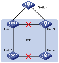
Configuration procedure
# Enable the Resilient ARP function.
<Sysname> system-view
[Sysname] resilient-arp enable
# Configure the Resilient ARP packets to be sent through the VLAN-interface 2.
[Sysname] resilient-arp interface Vlan-interface 2