- Table of Contents
-
- H3C S3600 Operation Manual-Release 1602(V1.02)
- 00-1Cover
- 00-2Product Overview
- 01-CLI Operation
- 02-Login Operation
- 03-Configuration File Management Operation
- 04-VLAN Operation
- 05-IP Address and Performance Operation
- 06-Voice VLAN Operation
- 07-GVRP Operation
- 08-Port Basic Configuration Operation
- 09-Link Aggregation Operation
- 10-Port Isolation Operation
- 11-Port Security-Port Binding Operation
- 12-DLDP Operation
- 13-MAC Address Table Management Operation
- 14-Auto Detect Operation
- 15-MSTP Operation
- 16-Routing Protocol Operation
- 17-Multicast Operation
- 18-802.1x and System Guard Operation
- 19-AAA Operation
- 20-Web Authentication Operation
- 21-MAC Address Authentication Operation
- 22-VRRP Operation
- 23-ARP Operation
- 24-DHCP Operation
- 25-ACL Operation
- 26-QoS-QoS Profile Operation
- 27-Web Cache Redirection Operation
- 28-Mirroring Operation
- 29-IRF Fabric Operation
- 30-Cluster Operation
- 31-PoE-PoE Profile Operation
- 32-UDP Helper Operation
- 33-SNMP-RMON Operation
- 34-NTP Operation
- 35-SSH Operation
- 36-File System Management Operation
- 37-FTP-SFTP-TFTP Operation
- 38-Information Center Operation
- 39-System Maintenance and Debugging Operation
- 40-VLAN-VPN Operation
- 41-HWPing Operation
- 42-IPv6 Management Operation
- 43-DNS Operation
- 44-Smart Link-Monitor Link Operation
- 45-Access Management Operation
- 46-Appendix
- Related Documents
-
| Title | Size | Download |
|---|---|---|
| 17-Multicast Operation | 1.39 MB |
Information Transmission in the Unicast Mode
Information Transmission in the Broadcast Mode
Information Transmission in the Multicast Mode
Advantages and Applications of Multicast
Multicast Packet Forwarding Mechanism
Implementation of the RPF Mechanism
2 Common Multicast Configuration
Common Multicast Configuration
Enabling Multicast Packet Buffering
Configuring Limit on the Number of Route Entries
Configuring Suppression on the Multicast Source Port
Clearing Multicast Forwarding and Routing Entries
Configuring a Multicast MAC Address Entry
Configuring Dropping Unknown Multicast Packets
Displaying and Maintaining Common Multicast Configuration
Enhancements Provided by IGMPv2
Configuring Options Related to IGMP Query Messages
Configuring the Maximum Allowed Number of Multicast Groups
Configuring a Multicast Group Filter
Removing Joined IGMP Groups from an Interface
Displaying and Maintaining IGMP
Filtering the Registration Packets from DR to RP
Disabling RPT-to-SPT Switchover
Configuring Common PIM Parameters
Configuring a Multicast Data Filter
Configuring the Hello Interval
Configuring Multicast Source Lifetime
Clearing the Related PIM Entries
Displaying and Maintaining PIM
Configuring MSDP Basic Functions
Configuring MSDP Basic Functions
Configuring Connection Between MSDP Peers
Configuring Description Information for MSDP Peers
Configuring an MSDP Mesh Group
Configuring MSDP Peer Connection Control
Configuring SA Message Transmission
Configuring RP Address in SA Messages
Configuring the Transmission and Filtering of SA Request Messages
Configuring a Rule for Filtering the Multicast Sources of SA Messages
Configuring a Rule for Filtering Received and Forwarded SA Messages
Displaying and Maintaining MSDP
Troubleshooting MSDP Configuration
MSDP Peer Always in the Down State
No SA Entry in the SA Cache of the Router
Basic Concepts in IGMP Snooping
Work Mechanism of IGMP Snooping
Configuring the Version of IGMP Snooping
Configuring Fast Leave Processing
Configuring a Multicast Group Filter
Configuring the Maximum Number of Multicast Groups on a Port
Configuring IGMP Snooping Querier
Suppressing Flooding of Unknown Multicast Traffic in a VLAN
Configuring Static Member Port for a Multicast Group
Configuring a Static Router Port
Configuring a Port as a Simulated Group Member
Configuring a VLAN Tag for Query Messages
Displaying and Maintaining IGMP Snooping
IGMP Snooping Configuration Examples
![]()
In this manual, the term “router” refers to a router in the generic sense or a Layer 3 Ethernet switch running an IP multicast protocol.
The following features are added in this version:
l Enabling Multicast Packet Buffering
l Configuring Multicast Source Lifetime
l IGMPv3 Snooping features. Refer to Configuring the Version of IGMP Snooping and Configuring a Port as a Simulated Group Member
l Suppressing Flooding of Unknown Multicast Traffic in a VLAN
l Configuring Static Member Port for a Multicast Group
Multicast Overview
With the development of the Internet, more and more interaction services such as data, voice, and video services are running on the networks. In addition, highly bandwidth- and time-critical services, such as e-commerce, Web conference, online auction, video on demand (VoD), and tele-education have come into being. These services have higher requirements for information security, legal use of paid services, and network bandwidth.
Information Transmission in the Unicast Mode
In unicast, the system establishes a separate data transmission channel for each user requiring this information, and sends a separate copy of the information to the user, as shown in Figure 1-1:
Figure 1-1 Information transmission in the unicast mode
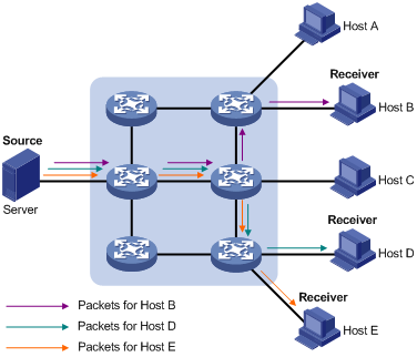
Assume that Hosts B, D and E need this information. The source server establishes transmission channels for the devices of these users respectively. As the transmitted traffic over the network is in direct proportion to the number of users that receive this information, when a large number of users need this information, the server must send many pieces of information with the same content to the users. Therefore, the limited bandwidth becomes the bottleneck in information transmission. This shows that unicast is not good for the transmission of a great deal of information.
Information Transmission in the Broadcast Mode
When you adopt broadcast, the system transmits information to all users on a network. Any user on the network can receive the information, no matter the information is needed or not. Figure 1-2 shows information transmission in broadcast mode.
Figure 1-2 Information transmission in the broadcast mode
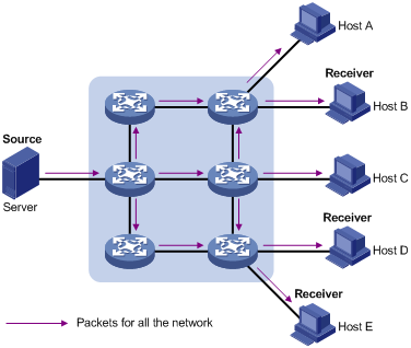
Assume that Hosts B, D, and E need the information. The source server broadcasts this information through routers, and Hosts A and C on the network also receive this information.
As we can see from the information transmission process, the security and legal use of paid service cannot be guaranteed. In addition, when only a small number of users on the same network need the information, the utilization ratio of the network resources is very low and the bandwidth resources are greatly wasted.
Information Transmission in the Multicast Mode
As described in the previous sections, unicast is suitable for networks with sparsely distributed users, whereas broadcast is suitable for networks with densely distributed users. When the number of users requiring information is not certain, unicast and broadcast deliver a low efficiency.
Multicast solves this problem. When some users on a network require specified information, the multicast information sender (namely, the multicast source) sends the information only once. With multicast distribution trees established for multicast data packets through multicast routing protocols, the packets are duplicated and distributed at the nearest nodes, as shown in Figure 1-3:
Figure 1-3 Information transmission in the multicast mode
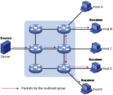
Assume that Hosts B, D and E need the information. To transmit the information to the right users, it is necessary to group Hosts B, D and E into a receiver set. The routers on the network duplicate and distribute the information based on the distribution of the receivers in this set. Finally, the information is correctly delivered to Hosts B, D, and E.
The advantages of multicast over unicast are as follows:
l No matter how many receivers exist, there is only one copy of the same multicast data flow on each link.
l With the multicast mode used to transmit information, an increase of the number of users does not add to the network burden remarkably.
The advantages of multicast over broadcast are as follows:
l A multicast data flow can be sent only to the receiver that requires the data.
l Multicast brings no waste of network resources and makes proper use of bandwidth.
Roles in Multicast
The following roles are involved in multicast transmission:
l An information sender is referred to as a multicast source (“Source” in Figure 1-3).
l Each receiver is a multicast group member (“Receiver” in Figure 1-3).
l All receivers interested in the same information form a multicast group. Multicast groups are not subject to geographic restrictions.
l A router that supports Layer 3 multicast is called multicast router or Layer 3 multicast device. In addition to providing multicast routing, a multicast router can also manage multicast group members.
For a better understanding of the multicast concept, you can assimilate multicast transmission to the transmission of TV programs, as shown in Table 1-1.
Table 1-1 An analogy between TV transmission and multicast transmission
|
Step |
TV transmission |
Multicast transmission |
|
1 |
A TV station transmits a TV program through a television channel. |
A multicast source sends multicast data to a multicast group. |
|
2 |
A user tunes the TV set to the channel. |
A receiver joins the multicast group. |
|
3 |
The user starts to watch the TV program transmitted by the TV station via the channel. |
The receiver starts to receive the multicast data that the source sends to the multicast group. |
|
4 |
The user turns off the TV set. |
The receiver leaves the multicast group. |
![]()
l A multicast source does not necessarily belong to a multicast group. Namely, a multicast source is not necessarily a multicast data receiver.
l A multicast source can send data to multiple multicast groups at the same time, and multiple multicast sources can send data to the same multicast group at the same time.
Advantages and Applications of Multicast
Advantages of multicast
Advantages of multicast include:
l Enhanced efficiency: Multicast decreases network traffic and reduces server load and CPU load.
l Optimal performance: Multicast reduces redundant traffic.
l Distributive application: Multicast makes multiple-point application possible.
Application of multicast
The multicast technology effectively addresses the issue of point-to-multipoint data transmission. By enabling high-efficiency point-to-multipoint data transmission, over an IP network, multicast greatly saves network bandwidth and reduces network load.
Multicast provides the following applications:
l Applications of multimedia and flow media, such as Web TV, Web radio, and real-time video/audio conferencing.
l Communication for training and cooperative operations, such as remote education.
l Database and financial applications (stock), and so on.
l Any point-to-multiple-point data application.
Multicast Models
Based on the multicast source processing modes, there are three multicast models:
l Any-source multicast (ASM)
l Source-filtered multicast (SFM)
l Source-specific multicast (SSM)
ASM model
In the ASM model, any sender can become a multicast source and send information to a multicast group; numbers of receivers can join a multicast group identified by a group address and obtain multicast information addressed to that multicast group. In this model, receivers are not aware of the position of a multicast source in advance. However, they can join or leave the multicast group at any time.
SFM model
The SFM model is derived from the ASM model. From the view of a sender, the two models have the same multicast group membership architecture.
Functionally, the SFM model is an extension of the ASM model. In the SFM model, the upper layer software checks the source address of received multicast packets so as to permit or deny multicast traffic from specific sources. Therefore, receivers can receive the multicast data from only part of the multicast sources. From the view of a receiver, multicast sources are not all valid: they are filtered.
SSM model
In the practical life, users may be interested in the multicast data from only certain multicast sources. The SSM model provides a transmission service that allows users to specify the multicast sources they are interested in at the client side.
The radical difference between the SSM model and the ASM model is that in the SSM model, receivers already know the locations of the multicast sources by some means. In addition, the SSM model uses a multicast address range that is different from that of the ASM model, and dedicated multicast forwarding paths are established between receivers and the specified multicast sources.
Multicast Architecture
The purpose of IP multicast is to transmit information from a multicast source to receivers in the multicast mode and to satisfy information requirements of receivers. You should be concerned about:
l Host registration: What receivers reside on the network?
l Technologies of discovering a multicast source: Which multicast source should the receivers receive information from?
l Multicast addressing mechanism: Where should the multicast source transports information?
l Multicast routing: How is information transported?
IP multicast is a kind of peer-to-peer service. Based on the protocol layer sequence from bottom to top, the multicast mechanism contains addressing mechanism, host registration, multicast routing, and multicast application:
l Addressing mechanism: Information is sent from a multicast source to a group of receivers through multicast addresses.
l Host registration: A receiving host joins and leaves a multicast group dynamically using the membership registration mechanism.
l Multicast routing: A router or switch transports packets from a multicast source to receivers by building a multicast distribution tree with multicast routes.
Multicast Address
As receivers are multiple hosts in a multicast group, you should be concerned about the following questions:
l What destination should the information source send the information to in the multicast mode?
l How to select the destination address?
These questions are about multicast addressing. To enable the communication between the information source and members of a multicast group (a group of information receivers), network-layer multicast addresses, namely, IP multicast addresses must be provided. In addition, a technology must be available to map IP multicast addresses to link-layer MAC multicast addresses. The following sections describe these two types of multicast addresses:
IP multicast address
Internet Assigned Numbers Authority (IANA) categorizes IP addresses into five classes: A, B, C, D, and E. Unicast packets use IP addresses of Class A, B, and C based on network scales. Class D IP addresses are used as destination addresses of multicast packets. Class D address must not appear in the IP address field of a source IP address of IP packets. Class E IP addresses are reserved for future use.
In unicast data transport, a data packet is transported hop by hop from the source address to the destination address. In an IP multicast environment, there are a group of destination addresses (called group address), rather than one address. All the receivers join a group. Once they join the group, the data sent to this group of addresses starts to be transported to the receivers. All the members in this group can receive the data packets. This group is a multicast group.
A multicast group has the following characteristics:
l The membership of a group is dynamic. A host can join and leave a multicast group at any time.
l A multicast group can be either permanent or temporary.
l A multicast group whose addresses are assigned by IANA is a permanent multicast group. It is also called reserved multicast group.
Note that:
l The IP addresses of a permanent multicast group keep unchanged, while the members of the group can be changed.
l There can be any number of, or even zero, members in a permanent multicast group.
l Those IP multicast addresses not assigned to permanent multicast groups can be used by temporary multicast groups.
Class D IP addresses range from 224.0.0.0 to 239.255.255.255. For details, see Table 1-2.
Table 1-2 Range and description of Class D IP addresses
|
Class D address range |
Description |
|
224.0.0.0 to 224.0.0.255 |
Reserved multicast addresses (IP addresses for permanent multicast groups). The IP address 224.0.0.0 is reserved. Other IP addresses can be used by routing protocols. |
|
224.0.1.0 to 231.255.255.255 233.0.0.0 to 238.255.255.255 |
Available any-source multicast (ASM) multicast addresses (IP addresses for temporary groups). They are valid for the entire network. |
|
232.0.0.0 to 232.255.255.255 |
Available source-specific multicast (SSM) multicast group addresses. |
|
239.0.0.0 to 239.255.255.255 |
Administratively scoped multicast addresses, which are for specific local use only. |
As specified by IANA, the IP addresses ranging from 224.0.0.0 to 224.0.0.255 are reserved for network protocols on local networks. The following table lists commonly used reserved IP multicast addresses:
Table 1-3 Reserved IP multicast addresses
|
Class D address range |
Description |
|
224.0.0.1 |
Address of all hosts |
|
224.0.0.2 |
Address of all multicast routers |
|
224.0.0.3 |
Unassigned |
|
224.0.0.4 |
Distance Vector Multicast Routing Protocol (DVMRP) routers |
|
224.0.0.5 |
Open Shortest Path First (OSPF) routers |
|
224.0.0.6 |
Open Shortest Path First designated routers (OSPF DR) |
|
224.0.0.7 |
Shared tree routers |
|
224.0.0.8 |
Shared tree hosts |
|
224.0.0.9 |
RIP-2 routers |
|
224.0.0.11 |
Mobile agents |
|
224.0.0.12 |
DHCP server/relay agent |
|
224.0.0.13 |
All Protocol Independent Multicast (PIM) routers |
|
224.0.0.14 |
Resource Reservation Protocol (RSVP) encapsulation |
|
224.0.0.15 |
All core-based tree (CBT) routers |
|
224.0.0.16 |
The specified subnetwork bandwidth management (SBM) |
|
224.0.0.17 |
All SBMS |
|
224.0.0.18 |
Virtual Router Redundancy Protocol (VRRP) |
|
224.0.0.19 to 224.0.0.255 |
Other protocols |
![]()
Like having reserved the private network segment 10.0.0.0/8 for unicast, IANA has also reserved the network segment 239.0.0.0/8 for multicast. These are administratively scoped addresses. With the administratively scoped addresses, you can define the range of multicast domains flexibly to isolate IP addresses between different multicast domains, so that the same multicast address can be used in different multicast domains without causing collisions.
Ethernet multicast MAC address
When a unicast IP packet is transported in an Ethernet network, the destination MAC address is the MAC address of the receiver. When a multicast packet is transported in an Ethernet network, a multicast MAC address is used as the destination address because the destination is a group with an uncertain number of members.
As stipulated by IANA, the high-order 24 bits of a multicast MAC address are 0x01005e, while the low-order 23 bits of a MAC address are the low-order 23 bits of the multicast IP address. Figure 1-4 describes the mapping relationship:
Figure 1-4 Multicast address mapping
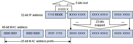
The high-order four bits of the IP multicast address are 1110, representing the multicast ID. Only 23 bits of the remaining 28 bits are mapped to a MAC address. Thus, five bits of the multicast IP address are lost. As a result, 32 IP multicast addresses are mapped to the same MAC address.
Multicast Protocols
![]()
l Generally, we refer to IP multicast working at the network layer as Layer 3 multicast and the corresponding multicast protocols as Layer 3 multicast protocols, which include IGMP, PIM, and MSDP; we refer to IP multicast working at the data link layer as Layer 2 multicast and the corresponding multicast protocols as Layer 2 multicast protocols, which include IGMP Snooping.
l This section provides only general descriptions about applications and functions of the Layer 2 and Layer 3 multicast protocols in a network. For details about these protocols, refer to the related chapters of this manual.
Layer 3 multicast protocols
Layer 3 multicast protocols include multicast group management protocols and multicast routing protocols. Figure 1-5 describes where these multicast protocols are in a network.
Figure 1-5 Positions of Layer 3 multicast protocols
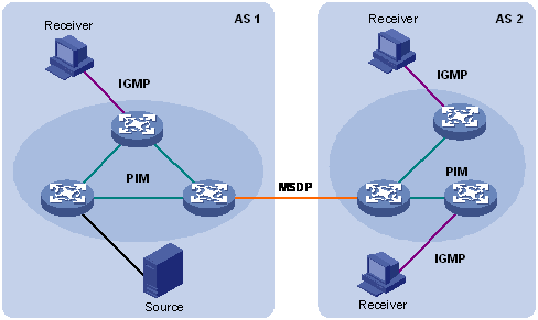
1) Multicast management protocols
Typically, the Internet Group Management Protocol (IGMP) is used between hosts and Layer 3 multicast devices directly connected with the hosts. These protocols define the mechanism of establishing and maintaining group memberships between hosts and Layer 3 multicast devices.
2) Multicast routing protocols
A multicast routing protocol runs on Layer 3 multicast devices to establish and maintain multicast routes and forward multicast packets correctly and efficiently. Multicast routes constitute a loop-free data transmission path from a data source to multiple receivers, namely a multicast distribution tree.
In the ASM model, multicast routes come in intra-domain routes and inter-domain routes.
l An intra-domain multicast routing protocol is used to discover multicast sources and build multicast distribution trees within an autonomous system (AS) so as to deliver multicast data to receivers. Among a variety of mature intra-domain multicast routing protocols, Protocol Independent Multicast (PIM) is a popular one. Based on the forwarding mechanism, PIM comes in two modes – dense mode (often referred to as PIM-DM) and sparse mode (often referred to as PIM-SM).
l An inter-domain multicast routing protocol is used for delivery of multicast information between two ASs. So far, mature solutions include Multicast Source Discovery Protocol (MSDP).
For the SSM model, multicast routes are not divided into inter-domain routes and intra-domain routes. Since receivers know the position of the multicast source, channels established through PIM-SM are sufficient for multicast information transport.
Layer 2 multicast protocols
Layer 2 multicast protocols include IGMP Snooping and multicast VLAN. Figure 1-6 shows where these protocols are in the network.
Figure 1-6 Positions of Layer 2 multicast protocols
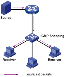
Running on Layer 2 devices, Internet Group Management Protocol Snooping (IGMP Snooping) are multicast constraining mechanisms that manage and control multicast groups by listening to and analyzing IGMP messages exchanged between the hosts and Layer 3 multicast devices, thus effectively controlling the flooding of multicast data in a Layer 2 network.
Multicast Packet Forwarding Mechanism
In a multicast model, a multicast source sends information to the host group identified by the multicast group address in the destination address field of the IP packets. Therefore, to deliver multicast packets to receivers located in different parts of the network, multicast routers on the forwarding path usually need to forward multicast packets received on one incoming interface to multiple outgoing interfaces. Compared with a unicast model, a multicast model is more complex in the following aspects.
l In the network, multicast packet transmission is based on the guidance of the multicast forwarding table derived from the unicast routing table or the multicast routing table specially provided for multicast.
l To process the same multicast information from different peers received on different interfaces of the same device, every multicast packet is subject to a Reverse Path Forwarding (RPF) check on the incoming interface. The result of the RPF check determines whether the packet will be forwarded or discarded. The RPF check mechanism is the basis for most multicast routing protocols to implement multicast forwarding.
The RPF mechanism enables multicast devices to forward multicast packets correctly based on the multicast route configuration. In addition, the RPF mechanism also helps avoid data loops caused by various reasons.
Implementation of the RPF Mechanism
Upon receiving a multicast packet that a multicast source S sends to a multicast group G, the multicast device first searches its multicast forwarding table:
1) If the corresponding (S, G) entry exists, and the interface on which the packet actually arrived is the incoming interface in the multicast forwarding table, the router forwards the packet to all the outgoing interfaces.
2) If the corresponding (S, G) entry exists, but the interface on which the packet actually arrived is not the incoming interface in the multicast forwarding table, the multicast packet is subject to an RPF check.
l If the result of the RPF check shows that the RPF interface is the incoming interface of the existing (S, G) entry, this means that the (S, G) entry is correct but the packet arrived from a wrong path and is to be discarded.
l If the result of the RPF check shows that the RPF interface is not the incoming interface of the existing (S, G) entry, this means that the (S, G) entry is no longer valid. The router replaces the incoming interface of the (S, G) entry with the interface on which the packet actually arrived and forwards the packet to all the outgoing interfaces.
3) If no corresponding (S, G) entry exists in the multicast forwarding table, the packet is also subject to an RPF check. The router creates an (S, G) entry based on the relevant routing information and using the RPF interface as the incoming interface, and installs the entry into the multicast forwarding table.
l If the interface on which the packet actually arrived is the RPF interface, the RPF check is successful and the router forwards the packet to all the outgoing interfaces.
l If the interface on which the packet actually arrived is not the RPF interface, the RPF check fails and the router discards the packet.
RPF Check
The basis for an RPF check is a unicast route. A unicast routing table contains the shortest path to each destination subnet. A multicast routing protocol does not independently maintain any type of unicast route; instead, it relies on the existing unicast routing information in creating multicast routing entries.
When performing an RPF check, a router searches its unicast routing table. The specific process is as follows: The router automatically chooses an optimal unicast route by searching its unicast routing table, using the IP address of the “packet source” as the destination address. The outgoing interface in the corresponding routing entry is the RPF interface and the next hop is the RPF neighbor. The router considers the path along which the packet from the RPF neighbor arrived on the RPF interface to be the shortest path that leads back to the source.
Assume that unicast routes exist in the network, as shown in Figure 1-7. Multicast packets travel along the SPT from the multicast source to the receivers.
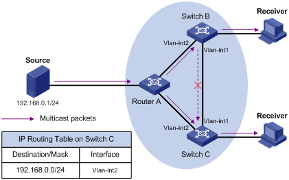
l A multicast packet from Source arrives to VLAN-interface 1 of Switch C, and the corresponding forwarding entry does not exist in the multicast forwarding table of Switch C. Switch C performs an RPF check, and finds in its unicast routing table that the outgoing interface to 192.168.0.0/24 is VLAN-interface 2. This means that the interface on which the packet actually arrived is not the RPF interface. The RPF check fails and the packet is discarded.
l A multicast packet from Source arrives to VLAN-interface 2 of Switch C, and the corresponding forwarding entry does not exist in the multicast forwarding table of Switch C. The router performs an RPF check, and finds in its unicast routing table that the outgoing interface to 192.168.0.0/24 is the interface on which the packet actually arrived. The RPF check succeeds and the packet is forwarded.
![]()
l In this manual, the term “router” refers to a router in the generic sense or a Layer 3 Ethernet switch running an IP multicast protocol.
l S3600-SI series Ethernet switches support only Configuring Suppression on the Multicast Source Port, Configuring a Multicast MAC Address Entry, and Configuring Dropping Unknown Multicast Packets, while S3600-EI series Ethernet switches support all multicast features.
Common Multicast Configuration
Table 2-1 Complete the following tasks to perform common multicast configurations:
|
Task |
Remarks |
|
Optional |
|
|
Required |
|
|
Optional |
|
|
Optional |
|
|
Optional |
|
|
Optional |
|
|
Optional |
|
|
Optional |
Enabling Multicast Packet Buffering
This mechanism buffers multicast packets at the price of impact to the CPU and extra memory usage.
Follow these steps to enable multicast packet buffering:
|
To do... |
Use the command... |
Remarks |
|
Enter system view |
system-view |
— |
|
Enable multicast packet buffering |
multicast storing-enable |
Optional By default, this function is disabled. |
|
Configure the maximum number of packets that can be buffered per multicast forwarding entry |
multicast storing-packet packet-number |
Optional The system default is 100. |
![]()
The multicast packet buffering feature should be enabled only before multicast routing is enabled.
Enabling Multicast Routing
Follow these steps to enable multicast routing:
|
To do... |
Use the command... |
Remarks |
|
Enter system view |
system-view |
— |
|
Enable multicast routing |
multicast routing-enable |
Required Disabled by default. |
![]()
To guard against attacks on any socket not in use, S3600 series provide the following functions to achieve enhanced security:
l The system opens the RAW Socket used for multicast routing only if multicast routing is enabled.
l When you disable multicast routing, the RAW Socket used for multicast routing is also closed.
![]()
IGMP, PIM and MSDP configurations can be performed or can take effect only if multicast routing has been enabled.
Configuring Limit on the Number of Route Entries
Too many multicast routing entries can exhaust the router’s memory and thus result in lower router performance. Therefore, the number of multicast routing entries should be limited.
Follow these steps to configure limit on the number of route entries:
|
To do... |
Use the command... |
Remarks |
|
Enter system view |
system-view |
— |
|
Configure the maximum number of multicast route entries |
multicast route-limit limit |
Optional By default, the maximum number of multicast route entries is 256 |
Configuring Suppression on the Multicast Source Port
Some users may deploy unauthorized multicast servers on the network. This affects the use of network bandwidth and transmission of multicast data of authorized users by taking network resources. You can configure multicast source port suppression on certain ports to prevent unauthorized multicast servers attached to these ports from sending multicast traffic to the network.
Configuring multicast source port suppression in system view
Follow these steps to configure multicast source port suppression in system view:
|
To do... |
Use the command... |
Remarks |
|
Enter system view |
system-view |
— |
|
Configure multicast source port suppression |
multicast-source-deny [ interface interface-list ] |
Optional Multicast source port suppression is disabled by default. |
Configuring multicast source port suppression in Ethernet port view
Follow these steps to configure multicast source port suppression in Ethernet port view:
|
To do... |
Use the command... |
Remarks |
|
Enter system view |
system-view |
— |
|
Enter Ethernet port view |
interface interface-type interface-number |
— |
|
Configure multicast source port suppression |
multicast-source-deny |
Optional Multicast source port suppression is disabled by default. |
Clearing Multicast Forwarding and Routing Entries
To release system memory, you can use reset commands to clear multicast routing entries, multicast forwarding entries, and related statistics information stored in the device.
Follow these steps to clear the multicast-related entries and statistics:
|
To do... |
Use the command... |
Remarks |
|
Clear multicast forwarding entries and, with statistics specified, the corresponding statistics information |
reset multicast forwarding-table [ statistics ] { all | { group-address [ mask {mask | mask-length } ] | source-address [ mask { mask |mask-length } ] | incoming-interface interface-type interface-number } * } |
Use the reset commands in user view. |
|
Clear routing entries in the core multicast routing table |
reset multicast routing-table { all | { group-address [ mask { mask |mask-length } ] | source-address [ mask { mask | mask-length } ] | { incoming-interface interface-type interface-number } } * } |
Configuring a Multicast MAC Address Entry
In Layer 2 multicast, the system can add multicast forwarding entries dynamically through a Layer 2 multicast protocol. Alternatively, you can statically bind a port to a multicast MAC address entry by configuring a multicast MAC address entry manually.
Generally, when receiving a multicast packet for a multicast group not yet registered on the switch, the switch will flood the packet within the VLAN to which the port belongs. You can configure a static multicast MAC address entry to avoid this.
Follow these steps to configure a multicast MAC address entry in system view:
|
To do... |
Use the command... |
Remarks |
|
Enter system view |
system-view |
— |
|
Create a multicast MAC address entry |
mac-address multicast mac-address interface interface-list vlan vlan-id |
Required The mac-address argument must be a multicast MAC address. |
Follow these steps to configure a multicast MAC address entry in Ethernet port view:
|
To do... |
Use the command... |
Remarks |
|
Enter system view |
system-view |
— |
|
Enter Ethernet port view |
interface interface-type interface-number |
— |
|
Create a multicast MAC address entry. |
mac-address multicast mac-address vlan vlan-id |
Required The mac-address argument must be a multicast MAC address. |
![]()
l If the multicast MAC address entry to be created already exists, the system gives you a prompt.
l If you want to add a port to a multicast MAC address entry created through the mac-address multicast command, you need to remove the entry first, create this entry again, and then add the specified port to the forwarding ports of this entry.
l You cannot configure a multicast MAC address starting with 01005e on a device with IRF Fabric enabled.
l You cannot enable link aggregation on a port on which you have configured a multicast MAC address, and you cannot configure a multicast MAC address on an aggregation port.
l You cannot configure a multicast MAC address starting with 01005e in an IGMP-Snooping-enabled VLAN. You can do that if IGMP Snooping is not enabled in the VLAN.
Configuring Dropping Unknown Multicast Packets
Generally, if the multicast address of the multicast packet received on the switch is not registered on the local switch, the packet will be flooded in the VLAN. When the function of dropping unknown multicast packets is enabled, the switch will drop any multicast packets whose multicast address is not registered. Thus, the bandwidth is saved and the processing efficiency of the system is improved.
Follow these steps to configure dropping unknown multicast packet:
|
To do... |
Use the command... |
Remarks |
|
Enter system view |
system-view |
— |
|
Configure dropping unknown multicast packets |
unknown-multicast drop enable |
Required By default, the function of dropping unknown multicast packets is disabled. |
Tracing a Multicast Path
You can run the mtracert command to trace the path down which the multicast traffic flows from a given first-hop router to the last-hop router.
|
To do… |
Use the command… |
Remarks |
|
Trace a multicast path |
mtracert source-address [ [ last-hop-router-address ] group-address ] |
Required Available in any view |
Displaying and Maintaining Common Multicast Configuration
The information about the multicast forwarding table is mainly used for debugging. Generally, you can get the required information by checking the core multicast routing table.
Three kinds of tables affect multicast data transmission. Their correlations are as follows:
l Each multicast routing protocol has its own multicast routing table, such as PIM routing table.
l The information of different multicast routing protocols forms a general multicast routing table.
l Consistent with the multicast routing table, the multicast forwarding table is the table that guide multicast forwarding.
Follow these commands to display common multicast configuration:
|
To do... |
Use the command... |
Remarks |
|
Display the statistics information about multicast source port suppression |
display multicast-source-deny [ interface interface-type [ interface-number ] ] |
Available in any view |
|
Display the information about the multicast routing table |
display multicast routing-table [ group-address [ mask { mask | length } ] | source-address [ mask { mask | length } ] | incoming-interface { interface-type interface-number | register } ]* |
Available in any view |
|
Display the information about the multicast forwarding table |
display multicast forwarding-table [ group-address [ mask { mask | mask-length } ] | source-address [ mask { mask | mask-length } ] | incoming-interface { interface-type interface-number ] register } ]* |
Available in any view |
|
Display multicast forward table information containing port information |
display mpm forwarding-table [ group-address ] |
Available in any view |
|
Display the information about the IP multicast groups and MAC multicast groups in a VLAN or all VLANs |
display mpm group [ vlan vlan-id ] |
Available in any view |
|
Display the created multicast MAC table entries |
display mac-address multicast [ static { { { mac-address vlan vlan-id | vlan vlan-id } [ count ] } | count } ] |
Available in any view |
![]()
l In this manual, the term “router” refers to a router in the generic sense or a Layer 3 Ethernet switch running an IP multicast protocol.
l S3600-SI series Ethernet switches do not support IGMP.
When configuring IGMP, go to these sections for information you are interested in:
l Displaying and Maintaining IGMP
IGMP Overview
As a TCP/IP protocol responsible for IP multicast group member management, the Internet Group Management Protocol (IGMP) is used by IP hosts to establish and maintain their multicast group memberships to immediately neighboring multicast routers.
IGMP Versions
So far, there are three IGMP versions:
l IGMPv1 (documented in RFC 1112)
l IGMPv2 (documented in RFC 2236)
l IGMPv3 (documented in RFC 3376)
All IGMP versions support the any-source multicast (ASM) model. In addition, IGMPv3 provides strong support to the source-specific multicast (SSM) model.
Work Mechanism of IGMPv1
IGMPv1 manages multicast group memberships mainly based on the query and response mechanism.
Of multiple multicast routers on the same subnet, all the routers can hear IGMP membership report messages (often referred to as reports) from hosts, but only one router is needed for sending IGMP query messages (often referred to as queries). So, a querier election mechanism is required to determine which router will act as the IGMP querier on the subnet.
In IGMPv1, the designated router (DR) elected by a multicast routing protocol (such as PIM) serves as the IGMP querier.
For more information about a DR, refer to DR election.
Figure 3-1 Joining multicast groups
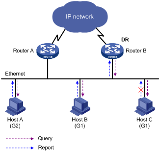
Assume that Host B and Host C are expected to receive multicast data addressed to multicast group G1, while Host A is expected to receive multicast data addressed to G2, as shown in Figure 3-1. The basic process that the hosts join the multicast groups is as follows:
1) The IGMP querier (Router B in the figure) periodically multicasts IGMP queries (with the destination address of 224.0.0.1) to all hosts and routers on the local subnet.
2) Upon receiving a query message, Host B or Host C (the delay timer of whichever expires first) sends an IGMP report to the multicast group address of G1, to announce its interest in G1. Assume it is Host B that sends the report message.
3) Host C, which is on the same subnet, hears the report from Host B for joining G1. Upon hearing the report, Host C will suppress itself from sending a report message for the same multicast group, because the IGMP routers (Router A and Router B) already know that at least one host on the local subnet is interested in G1. This mechanism, known as IGMP report suppression, helps reduce traffic over the local subnet.
4) At the same time, because Host A is interested in G2, it sends a report to the multicast group address of G2.
5) Through the above-mentioned query/report process, the IGMP routers learn that members of G1 and G2 are attached to the local subnet, and generate (*, G1) and (*, G2) multicast forwarding entries, which will be the basis for subsequent multicast forwarding, where * represents any multicast source.
6) When the multicast data addressed to G1 or G2 reaches an IGMP router, because the (*, G1) and (*, G2) multicast forwarding entries exist on the IGMP router, the router forwards the multicast data to the local subnet, and then the receivers on the subnet receive the data.
As IGMPv1 does not specifically define a Leave Group message, upon leaving a multicast group, an IGMPv1 host stops sending reports with the destination address being the address of that multicast group. If no member of a multicast group exists on the subnet, the IGMP routers will not receive any report addressed to that multicast group, so the routers will delete the multicast forwarding entries corresponding to that multicast group after a period of time.
Enhancements Provided by IGMPv2
Compared with IGMPv1, IGMPv2 provides the querier election mechanism and Leave Group mechanism.
Querier election mechanism
In IGMPv1, the DR elected by the Layer 3 multicast routing protocol (such as PIM) serves as the querier among multiple routers on the same subnet.
In IGMPv2, an independent querier election mechanism is introduced. The querier election process is as follows:
1) Initially, every IGMPv2 router assumes itself as the querier and sends IGMP general query messages (often referred to as general queries) to all hosts and routers on the local subnet (the destination address is 224.0.0.1).
2) Upon hearing a general query, every IGMPv2 router compares the source IP address of the query message with its own interface address. After comparison, the router with the lowest IP address wins the querier election and all other IGMPv2 routers become non-queriers.
3) All the non-queriers start a timer, known as “other querier present timer”. If a router receives an IGMP query from the querier before the timer expires, it resets this timer; otherwise, it assumes the querier to have timed out and initiates a new querier election process.
“Leave group” mechanism
In IGMPv1, when a host leaves a multicast group, it does not send any notification to the multicast router. The multicast router relies on IGMP query response timeout to know whether a group no longer has members. This adds to the leave latency.
In IGMPv2, on the other hand, when a host leaves a multicast group:
1) This host sends a Leave Group message (often referred to as leave message) to all routers (the destination address is 224.0.0.2) on the local subnet.
2) Upon receiving the leave message, the querier sends a configurable number of group-specific queries to the group being left. The destination address field and group address field of message are both filled with the address of the multicast group being queried.
3) One of the remaining members, if any on the subnet, of the group being queried should send a membership report within the maximum response time set in the query messages.
4) If the querier receives a membership report for the group within the maximum response time, it will maintain the memberships of the group; otherwise, the querier will assume that no hosts on the subnet are still interested in multicast traffic to that group and will stop maintaining the memberships of the group.
IGMP Proxy
A lot of stub networks (stub domains) are involved in the application of a multicast routing protocol (PIM-DM for example) over a large-scaled network. It is a hard work to configure and manage these stub networks.
To reduce the workload of configuration and management without affecting the multicast connection of leaf networks, you can configure an IGMP Proxy on a Layer 3 switch in the stub network (Switch B shown in Figure 3-2). The Layer 3 switch will then forward IGMP join or IGMP leave messages sent by the connected hosts. After IGMP Proxy is configured, the stub switch is no longer a PIM neighbor but a host for the exterior network. The Layer 3 switch receives the multicast data of corresponding groups only when it has directly attached multicast members.
Figure 3-2 Diagram for IGMP proxy
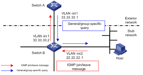
Figure 3-2 shows an IGMP Proxy diagram for a stub network. The upstream interface, VLAN-interface 1 of Switch B is the proxy interface for the downstream interface VLAN-interface 2.
Configure Switch B as follows:
Enable multicast routing, and then enable PIM and IGMP on VLAN-interface 1 and VLAN-interface 2. Run the igmp proxy command on VLAN-interface 1 to configure it as the proxy interface for VLAN-interface 2.
Configure Switch A as follows:
l Enable multicast routing, enable IGMP and PIM on VLAN-interface 1.
l Configure the pim neighbor-policy command to filter PIM neighbors in the network segment 33.33.33.0/24. That is, Switch A does not consider Switch B as its PIM neighbor.
In this case, when Switch B of the stub network receives from VLAN-interface 2 an IGMP join or IGMP leave message sent by the host, it changes the source address of the IGMP information to the address of VLAN-interface 1, 33.33.33.2, and sends the information to VLAN-interface 1 of Switch A. For Switch A, this works as if there is a host directly connected to VLAN-interface 1.
Similarly, when Switch B receives the IGMP general or group-specific query message from the Layer 3 Switch A, Switch B also changes the source address of the query message to the IP address of VLAN-interface 2, 22.22.22.1, and send the message from VLAN-interface 2.
Configuring IGMP
IGMP Configuration Task List
Complete the following tasks to configure IGMP:
|
Task |
Remarks |
|
Required |
|
|
Optional |
|
|
Optional |
|
|
Optional |
|
|
Optional |
|
|
Optional |
|
|
Optional |
|
|
Optional |
Enabling IGMP
First, IGMP must be enabled on the interface on which the multicast group memberships are to be established and maintained.
Follow these steps to enable IGMP:
|
To do... |
Use the command... |
Remarks |
|
Enter system view |
system-view |
— |
|
Enable IP multicast routing |
multicast routing-enable |
Required |
|
Enter interface view |
interface interface-type interface-number |
— |
|
Enable IGMP |
igmp enable |
Required Disabled by default |
![]()
Before performing the following configurations described in this chapter, you must enable multicast routing and enable IGMP on the specific interfaces.
Configuring IGMP Version
Follow these steps to configure IGMP version:
|
To do... |
Use the command... |
Remarks |
|
Enter system view |
system-view |
— |
|
Enter interface view |
interface interface-type interface-number |
— |
|
Configure the IGMP version |
igmp version { 1 | 2 } |
Optional The system default is IGMP version 2. |
![]()
IGMP versions cannot be switched to one another automatically. Therefore, all the interfaces on a subnet must be configured to use the same IGMP version.
Configuring Options Related to IGMP Query Messages
IGMP general query
An IGMP router sends IGMP general query messages to the local subnet periodically, and multicast receiver hosts send IGMP reports in response to IGMP queries. Thus the router learns which multicast groups on the subnet have active members.
IGMP group-specific query
On a multi-access network, the query router (querier for short) maintains group memberships. After the related features are configured, the IGMP querier sends a configurable number of IGMP group-specific queries at a configurable interval when it receives an IGMP leave message from the hosts.
Suppose a host in a multicast group decides to leave the multicast group. The related procedure is as follows:
l The host sends an IGMP leave message.
l When the IGMP querier receives the message, it sends robust-value IGMP group-specific query messages at the interval of lastmember-queryinterval.
l If other hosts are interested in the group after receiving the IGMP group-specific query message from the querier, they must send IGMP report messages within the maximum response time specified in the query messages.
l If the IGMP querier receives IGMP report messages from other hosts within the period of robust-value x lastmember-queryinterval, it will maintain the membership of the group.
l If the IGMP querier does not receive IGMP report messages from other hosts after the period of robust-value x lastmember-queryinterval, it considers that the group has no members on the local subnet and removes the forwarding table entry for the group.
![]()
You can use the igmp max-response-time command to set the maximum response time for general IGMP query messages, while that of an IGMP group-specific query message is determined by robust-value x lastmember-queryinterval.
The procedure is only fit for the occasion where IGMP queriers run IGMP version 2.
IGMP querier election
On a subnet containing multiple IGMP-enabled interfaces, the one with the lowest IP address becomes the IGMP querier. If non-querier interfaces receive no query message within the period configured in the igmp timer other-querier-present command, the current IGMP querier is considered to be down. In this case, a new IGMP querier election process takes place.
The maximum response time of IGMP general query messages
When the host receives a general query message, it will set a timer for each of its multicast groups. The timer value is selected from 0 to the maximum response time at random. When the value of a timer decreases to 0, the host will send the membership information of the multicast group.
By configuring reasonable maximum response time, you can enable the host to respond to the query information quickly and enable the Layer 3 switch to understand the membership information of multicast groups quickly.
Follow these steps to configure options related to IGMP query messages:
|
To do... |
Use the command... |
Remarks |
|
Enter system view |
system-view |
— |
|
Enter interface view |
interface interface-type interface-number |
— |
|
Configure the query interval (interval of sending general queries) |
igmp timer query seconds |
Optional 60 seconds by default. |
|
Configure the interval of sending IGMP group-specific query messages |
igmp lastmember-queryinterval seconds |
Optional 1 second by default |
|
Configure the number of times of sending IGMP group-specific query messages |
igmp robust-count robust-value |
Optional 2 by default. |
|
Configure the other querier present timer |
igmp timer other-querier-present seconds |
Optional The system default is 120 seconds, namely twice the query interval. |
|
Configure the maximum response time of IGMP general queries |
igmp max-response-time seconds |
Optional 10 seconds by default. |
Configuring the Maximum Allowed Number of Multicast Groups
By configuring the maximum number of IGMP multicast groups allowed to be joined on an interface of the switch, you can control the number of programs on demand available for users attached to the interface, thus to control the bandwidth usage on the interface.
Follow these steps to configure the maximum number of multicast groups allowed on an interface:
|
To do... |
Use the command... |
Remarks |
|
Enter system view |
system-view |
— |
|
Enter interface view |
interface interface-type interface-number |
— |
|
Configure the maximum number of multicast groups allowed on the interface |
igmp group-limit limit |
Required The default is 256. |
![]()
l After the maximum number of multicast groups is reached, the interface will not join any new multicast group.
l If you configure the maximum number of multicast groups allowed on the interface to 1, a new group registered on the interface supersedes the existing one automatically.
l If the number of existing multicast groups is larger than the configured limit on the number of joined multicast groups on the interface, the device will remove the oldest entries automatically until the number of multicast groups on the interface conforms to the configured limit.
Configuring a Multicast Group Filter
A multicast router determines the group memberships in the specified subnet by analyzing the received IGMP reports. To restrict the hosts on the network attached to an interface from joining certain multicast groups, you can apply an ACL rule on the interface as a group filter that limits the range of multicast groups that the interface serves.
You can:
l Configure the range of multicast groups that the current interface will work for in interface view.
l Configure the range of multicast groups that the interface corresponding to the VLAN where the current port resides will work for in Ethernet port view.
Configuring a multicast group filter in interface view
Follow these steps to configure a multicast group filter in VLAN interface view:
|
To do... |
Use the command... |
Remarks |
|
|
Enter system view |
system-view |
— |
|
|
Enter interface view |
interface interface-type interface-number |
— |
|
|
Configuring a multicast group filter |
In VLAN interface view |
igmp group-policy acl-number [ 1 | 2 | port interface-list ] |
Optional No multicast group filter is configured by default |
|
In LoopBack interface view |
igmp group-policy acl-number [ 1 | 2 ] |
||
Configuring a multicast group filter in Ethernet port view
Follow these steps to configure a multicast group filter in Ethernet port view:
|
To do... |
Use the command... |
Remarks |
|
Enter system view |
system-view |
— |
|
Enter Ethernet port view |
interface interface-type interface-number |
— |
|
Configuring a multicast group filter |
igmp group-policy acl-number vlan vlan-id |
Optional No multicast group filter is configured by default. The port must belong to the specified VLAN. |
Configuring Simulated Joining
Generally, hosts running IGMP respond to the IGMP query messages of the IGMP querier. If hosts fail to respond for some reason, the multicast router may consider that there is no member of the multicast group on the local subnet and remove the corresponding path.
To avoid this from happening, you can configure a port of the IGMP-enabled VLAN interface as a multicast group member. When the port receives IGMP query messages, the simulated member host will respond. As a result, the subnet attached to the Layer 3 interface can continue to receive multicast traffic.
Through this configuration, the following functions can be implemented:
l When an Ethernet port is configured as a simulated member host, the switch sends an IGMP report through this port. Meanwhile, the simulated host sends the same IGMP report to itself and establishes a corresponding IGMP entry based on this report.
l When receiving an IGMP general query, the simulated host responds with an IGMP report. Meanwhile, the simulated host sends the same IGMP report to itself to ensure that the IGMP entry does not age out.
l When the simulated joining function is disabled on an Ethernet port, the simulated host sends an IGMP leave message.
Therefore, to ensure that IGMP entries will not age out, the port must receive IGMP general queries periodically.
Configuring simulated joining in interface view
Follow these steps to configure simulated joining in interface view:
|
To do... |
Use the command... |
Remarks |
|
|
Enter system view |
system-view |
— |
|
|
Enter interface view |
interface interface-type interface-number |
— |
|
|
Configure one or more ports in the VLAN as simulated member host(s) of the specified multicast group |
VLAN interface view |
igmp host-join group-address port interface-list |
Required Disabled by default |
|
LoopBack interface view |
igmp host-join group-address |
||
Configuring simulated joining in Ethernet port view
Follow these steps to configure simulated joining in Ethernet port view:
|
To do... |
Use the command... |
Remarks |
|
Enter system view |
system-view |
— |
|
Enter Ethernet port view |
interface interface-type interface-number |
— |
|
Configure the port in the specified VLAN as a simulated member host of the specified multicast group |
igmp host-join group-address vlan vlan-id |
Required Disabled by default |
![]()
l Before configuring simulated joining, you must enable IGMP in interface view first.
l If you configure simulated joining in Ethernet port view, the Ethernet port must belong to the specified VLAN; otherwise the configuration does not take effect.
Configuring IGMP Proxy
Follow these steps to configure IGMP proxy:
|
To do... |
Use the command... |
Remarks |
|
Enter system view |
system-view |
— |
|
Enter VLAN interface view |
interface Vlan-interface interface-number |
— |
|
Configure IGMP proxy |
igmp proxy Vlan-interface interface-number |
Required Disabled by default |
![]()
l You must enable the PIM protocol on the interface before configuring the igmp proxy command. Otherwise, the IGMP Proxy feature does not take effect.
l One interface cannot serve as the proxy interface for two or more interfaces.
l Generally, an interface serving as an IGMP querier cannot act as an IGMP proxy interface. If it is necessary to configure an IGMP querier interface as an IGMP proxy interface, you must configure the port that belongs to the proxy interface and connects to the upstream multicast device as a static router port. For details, see Configuring a Static Router Port.
Removing Joined IGMP Groups from an Interface
You can remove all the joined multicast groups from a particular interface or all interfaces of the switch, or remove a particular multicast group address or group address range from a particular interface or all interfaces.
Follow these steps to remove joined multicast groups from one or all interfaces:
|
To do... |
Use the command... |
Remarks |
|
Remove the specified group or all groups from the specified interface or all interfaces |
reset igmp group { all | interface interface-type interface-number { all | group-address [ group-mask ] } } |
This command is available in user view. |
![]()
After a multicast group is removed from an interface, the multicast group can join the group again.
Displaying and Maintaining IGMP
|
To do... |
Use the command... |
Remarks |
|
Display the membership information of the IGMP multicast group |
display igmp group [ group-address | interface interface-type interface-number ] |
Available in any view |
|
Display the IGMP configuration and running information of the interface |
display igmp interface [ interface-type interface-number ] |
Available in any view |
When configuring PIM, go to these sections for information you are interested in:
l Configuring Common PIM Parameters
l Displaying and Maintaining PIM
![]()
l In this manual, the term “router” refers to a router in the generic sense or a Layer 3 Ethernet switch running an IP multicast protocol.
l S3600-SI series Ethernet switches do not support PIM.
PIM Overview
Protocol Independent Multicast (PIM) provides IP multicast forwarding by leveraging static routes or unicast routing tables generated by any unicast routing protocol, such as Routing Information Protocol (RIP), open shortest path first (OSPF), Intermediate System to Intermediate System (IS-IS), or Border Gateway Protocol (BGP). Independent of the unicast routing protocols running on the device, multicast routing can be implemented as long as the corresponding multicast routing entries are created through unicast routes. PIM uses the Reverse Path Forwarding (RPF) mechanism to implement multicast forwarding. When a multicast packet arrives on an interface of the device, it is subject to an RPF check. If the RPF check succeeds, the device creates the corresponding routing entry and forwards the packet; if the RPF check fails, the device discards the packet.
Based on the forwarding mechanism, PIM falls into two modes:
l Protocol Independent Multicast–Dense Mode (PIM-DM), and
l Protocol Independent Multicast–Sparse Mode (PIM-SM).
![]()
To facilitate description, a network comprising PIM-capable routers is referred to as a “PIM domain” in this document.
Introduction to PIM-DM
PIM-DM is a type of dense mode multicast protocol. It uses the “push mode” for multicast forwarding, and is suitable for small-sized networks with densely distributed multicast members.
The basic implementation of PIM-DM is as follows:
l PIM-DM assumes that at least one multicast group member exists on each subnet of a network, and therefore multicast data is flooded to all nodes on the network. Then, branches without multicast forwarding are pruned from the forwarding tree, leaving only those branches that contain receivers. This “flood and prune” process takes place periodically, that is, pruned branches resume multicast forwarding when the pruned state times out and then data is re-flooded down these branches, and then are pruned again.
l When a new receiver on a previously pruned branch joins a multicast group, to reduce the join latency, PIM-DM uses a graft mechanism to resume data forwarding to that branch.
Generally speaking, the multicast forwarding path is a source tree, namely a forwarding tree with the multicast source as its “root” and multicast group members as its “leaves”. Because the source tree is the shortest path from the multicast source to the receivers, it is also called shortest path tree (SPT).
How PIM-DM Works
The working mechanism of PIM-DM is summarized as follows:
l Neighbor discovery
l SPT building
l Graft
Neighbor discovery
In a PIM domain, a PIM router discovers PIM neighbors, maintains PIM neighboring relationships with other routers, and builds and maintains SPTs by periodically multicasting hello messages to all other PIM routers (224.0.0.13).
![]()
Every activated interface on a router sends hello messages periodically, and thus learns the PIM neighboring information pertinent to the interface.
SPT building
The process of building an SPT is the process of “flood and prune”.
1) In a PIM-DM domain, when a multicast source S sends multicast data to a multicast group G, the multicast packet is first flooded throughout the domain: The router first performs RPF check on the multicast packet. If the packet passes the RPF check, the router creates an (S, G) entry and forwards the data to all downstream nodes in the network. In the flooding process, an (S, G) entry is created on all the routers in the PIM-DM domain.
2) Then, nodes without receivers downstream are pruned: A router having no receivers downstream sends a prune message to the upstream node to “tell” the upstream node to delete the corresponding interface from the outgoing interface list in the (S, G) entry and stop forwarding subsequent packets addressed to that multicast group down to this node.
![]()
l An (S, G) entry contains the multicast source address S, multicast group address G, outgoing interface list, and incoming interface.
l For a given multicast stream, the interface that receives the multicast stream is referred to as “upstream”, and the interfaces that forward the multicast stream are referred to as “downstream”.
A prune process is first initiated by a leaf router. As shown in Figure 4-1, a router without any receiver attached to it (the router connected with Host A, for example) sends a prune message, and this prune process goes on until only necessary branches are left in the PIM-DM domain. These branches constitute the SPT.
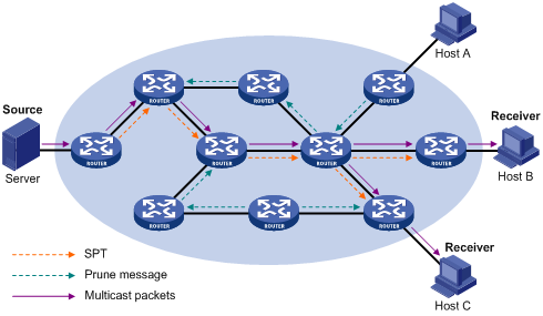
The “flood and prune” process takes place periodically. A pruned state timeout mechanism is provided. A pruned branch restarts multicast forwarding when the pruned state times out and then is pruned again when it no longer has any multicast receiver.
![]()
Pruning has a similar implementation in PIM-SM.
Graft
When a host attached to a pruned node joins a multicast group, to reduce the join latency, PIM-DM uses a graft mechanism to resume data forwarding to that branch. The process is as follows:
1) The node that need to receive multicast data sends a graft message hop by hop toward the source, as a request to join the SPT again.
2) Upon receiving this graft message, the upstream node puts the interface on which the graft was received into the forwarding state and responds with a graft-ack message to the graft sender.
Assert
If multiple multicast routers exist on a multi-access subnet, duplicate packets may flow to the same subnet. To shutoff duplicate flows, the assert mechanism is used for election of a single multicast forwarder on a multi-access network.
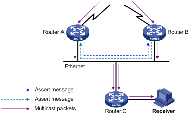
As shown in Figure 4-2, after Router A and Router B receive an (S, G) packet from the upstream node, they both forward the packet to the local subnet. As a result, the downstream node Router C receives two identical multicast packets, and both Router A and Router B, on their own local interface, receive a duplicate packet forwarded by the other. Upon detecting this condition, both routers send an assert message to all PIM routers (224.0.0.13) through the interface on which the packet was received. The assert message contains the following information: the multicast source address (S), the multicast group address (G), and the preference and metric of the unicast route to the source. By comparing these parameters, either Router A or Router B becomes the unique forwarder of the subsequent (S, G) packets on the multi-access subnet. The comparison process is as follows:
1) The router with a higher unicast route preference to the source wins;
2) If both routers have the same unicast route preference to the source, the router with a smaller metric to the source wins;
3) If there is a tie in route metric to the source, the router with a higher IP address of the local interface wins.
Introduction to PIM-SM
PIM-DM uses the “flood and prune” principle to build SPTs for multicast data distribution. Although an SPT has the shortest path, it is built with a low efficiency. Therefore the PIM-DM mod is not suitable for large- and medium-sized networks.
PIM-SM is a type of sparse mode multicast protocol. It uses the “pull mode” for multicast forwarding, and is suitable for large- and medium-sized networks with sparsely and widely distributed multicast group members.
The basic implementation of PIM-SM is as follows:
l PIM-SM assumes that no hosts need to receive multicast data. In the PIM-SM mode, routers must specifically request a particular multicast stream before the data is forwarded to them. The core task for PIM-SM to implement multicast forwarding is to build and maintain rendezvous point trees (RPTs). An RPT is rooted at a router in the PIM domain as the common node, or rendezvous point (RP), through which the multicast data travels along the RPT and reaches the receivers.
l When a receiver is interested in the multicast data addressed to a specific multicast group, the router connected to this receiver sends a join message to the RP corresponding to that multicast group. The path along which the message goes hop by hop to the RP forms a branch of the RPT.
l When a multicast source sends a multicast packet to a multicast group, the router directly connected with the multicast source first registers the multicast source with the RP by sending a register message to the RP by unicast. The arrival of this message at the RP triggers the establishment of an SPT. Then, the multicast source sends subsequent multicast packets along the SPT to the RP. Upon reaching the RP, the multicast packet is duplicated and delivered to the receivers along the RPT.
Multicast traffic is duplicated only where the distribution tree branches, and this process automatically repeats until the multicast traffic reaches the receivers.
How PIM-SM Works
The working mechanism of PIM-SM is summarized as follows:
l Neighbor discovery
l DR election
l RP discovery
l RPT building
l Multicast source registration
l Switchover from RPT to SPT
l Assert
Neighbor discovery
PIM-SM uses exactly the same neighbor discovery mechanism as PIM-DM does. Refer to Neighbor discovery.
DR election
A DR must be elected in a multi-access network, no matter this network connects to multicast sources or to receivers. The DR at the receiver side sends join messages to the RP; the DR at the multicast source side sends register messages to the RP.
![]()
l A DR is elected on a multi-access subnet by means of comparison of the priorities and IP addresses carried in hello messages. An elected DR is substantially meaningful to PIM-SM. PIM-DM itself does not require a DR. However, if IGMPv1 runs on any multi-access network in a PIM-DM domain, a DR must be elected to act as the IGMPv1 querier on that multi-access network.
l IGMP must be enabled on a device that acts as a DR before receivers attached to this device can join multicast groups through this DR.
As shown in Figure 4-3, the DR election process is as follows:
1) Routers on the multi-access network send hello messages to one another. The hello messages contain the router priority for DR election. The router with the highest DR priority will become the DR.
2) In the case of a tie in the router priority, or if any router in the network does not support carrying the DR-election priority in hello messages, the router with the highest IP address will win the DR election.
When the DR fails, a timeout in receiving hello message triggers a new DR election process among the other routers.
![]()
l S3600 series Ethernet switches do not support DR priority. DR election is based on IP addresses.
l In a PIM-DM domain, a DR serves as an IGMPv1 querier.
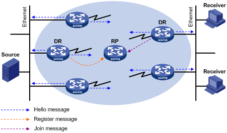
RP discovery
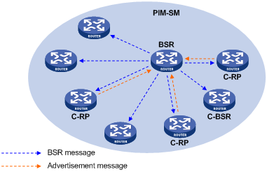
The RP is the core of a PIM-SM domain. For a small-sized, simple network, one RP is enough for forwarding information throughout the network, and the position of the RP can be statically specified on each router in the PIM-SM domain. In most cases, however, a PIM-SM network covers a wide area and a huge amount of multicast traffic needs to be forwarded through the RP. To lessen the RP burden and optimize the topological structure of the RPT, each multicast group should have its own RP. Therefore, a bootstrap mechanism is needed for dynamic RP election. For this purpose, a bootstrap router (BSR) should be configured.
As the administrative core of a PIM-SM domain, the BSR collects advertisement messages (C-RP-Adv messages) from candidate-RPs (C-RPs) and chooses the appropriate C-RP information for each multicast group to form an RP-Set, which is a database of mappings between multicast groups and RPs. The BSR then floods the RP-Set to the entire PIM-SM domain. Based on the information in these RP-Sets, all routers (including the DRs) in the network can calculate the location of the corresponding RPs.
A PIM-SM domain (or an administratively scoped region) can have only one BSR, but can have multiple candidate-BSRs (C-BSRs). Once the BSR fails, a new BSR is automatically elected from the C-BSRs through the bootstrap mechanism to avoid service interruption. Similarly, multiple C-RPs can be configured in a PIM-SM domain, and the position of the RP corresponding to each multicast group is calculated through the BSR mechanism.
Figure 4-4 shows the positions of C-RPs and the BSR in the network.
RPT building
Figure 4-5 Building an RPT in PIM-SM
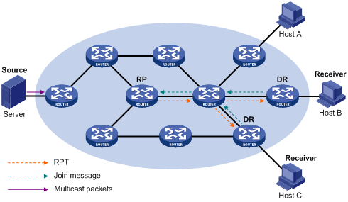
As shown in Figure 4-5, the process of building an RPT is as follows:
1) When a receiver joins a multicast group G, it uses an IGMP message to inform the directly connected DR.
2) Upon getting the receiver information, the DR sends a join message, which is hop by hop forwarded to the RP corresponding to the multicast group.
3) The routers along the path from the DR to the RP form an RPT branch. Each router on this branch generates a (*, G) entry in its forwarding table. The * means any multicast source. The RP is the root, while the DRs are the leaves, of the RPT.
The multicast data addressed to the multicast group G flows through the RP, reaches the corresponding DR along the established RPT, and finally is delivered to the receiver.
When a receiver is no longer interested in the multicast data addressed to a multicast group G, the directly connected DR sends a prune message, which goes hop by hop along the RPT to the RP. Upon receiving the prune message, the upstream node deletes its link with this downstream node from the outgoing interface list and checks whether it itself has receivers for that multicast group. If not, the router continues to forward the prune message to its upstream router.
Multicast source registration
The purpose of multicast source registration is to inform the RP about the existence of the multicast source.
Figure 4-6 Multicast registration
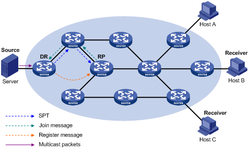
As shown in Figure 4-6, the multicast source registers with the RP as follows:
1) When the multicast source S sends the first multicast packet to a multicast group G, the DR directly connected with the multicast source, upon receiving the multicast packet, encapsulates the packet in a PIM register message, and sends the message to the corresponding RP by unicast.
2) When the RP receives the register message, on one hand, it extracts the multicast packet from the register message and forwards the multicast packet down the RPT, and, on the other hand, it sends an (S, G) join message hop by hop toward the multicast source. Thus, the routers along the path from the RP to the multicast source constitute an SPT branch. Each router on this branch generates a (S, G) entry in its forwarding table. The multicast source is the root, while the RP is the leaf, of the SPT.
3) The subsequent multicast data from the multicast source travels along the established SPT to the RP, and then the RP forwards the data along the RPT to the receivers. When the multicast traffic arrives at the RP along the SPT, the RP sends a register-stop message to the source-side DR by unicast to stop the source registration process.
Switchover from RPT to SPT
Initially, multicast traffic flows along an RPT from the RP to the receivers. Because the RPT is not necessarily the tree that has the shortest path, upon receiving the first multicast packet along the RPT, the receiver-side DR initiates an RPT-to-SPT switchover process, as follows:
1) First, the receiver-side DR sends an (S, G) join message hop by hop to the multicast source. When the join message reaches the source-side DR, all the routers on the path have installed the (S, G) entry in their forwarding table, and thus an SPT branch is established.
2) Subsequently, the receiver-side DR sends a prune message hop by hop to the RP. Upon receiving this prune message, the RP forwards it towards the multicast source, thus to implement RPT-to-SPT switchover.
After the RPT-to-SPT switchover, multicast data can be directly sent from the source to the receivers. PIM-SM builds SPTs through RPT-to-SPT switchover more economically than PIM-DM does through the “flood and prune” mechanism.
Assert
PIM-SM uses exactly the same assert mechanism as PIM-DM does. Refer to Assert.
Configuring PIM-DM
Enabling PIM-DM
With PIM-DM enabled, a router sends hello messages periodically to discover PIM neighbors and processes messages from PIM neighbors. When deploying a PIM-DM domain, you are recommended to enable PIM-DM on all interfaces of non-border routers.
Follow these steps to enable PIM-DM:
|
To do... |
Use the command... |
Remarks |
|
Enter system view |
system-view |
— |
|
Enable multicast routing |
multicast routing-enable |
Required Disabled by default |
|
Enter interface view |
interface interface-type interface-number |
— |
|
Enable PIM-DM |
pim dm |
Required Disabled by default |
Configuring PIM-SM
Complete the following tasks to configure PIM-SM:
|
Task |
Remarks |
|
Required |
|
|
Required |
|
|
Optional |
|
|
Optional |
|
|
Optional |
Enabling PIM-SM
With PIM-SM enabled, a router sends hello messages periodically to discover PIM neighbors and processes messages from PIM neighbors. When deploying a PIM-SM domain, you are recommended to enable PIM-SM on all interfaces of non-border routers (border routers are PIM-enabled routers located on the boundary of BSR admin-scope regions).
Follow these steps to enable PIM-SM:
|
To do... |
Use the command... |
Remarks |
|
Enter system view |
system-view |
— |
|
Enable multicast routing |
multicast routing-enable |
Required Disabled by default |
|
Enter interface view |
interface interface-type interface-number |
— |
|
Enable PIM-SM |
pim sm |
Required Disabled by default |
Configuring an RP
An RP can be manually configured or dynamically elected through the BSR mechanism. For a large PIM network, static RP configuration is a tedious job. Generally, static RP configuration is just a backup means for the dynamic RP election mechanism to enhance the robustness and operation manageability of a multicast network.
Configuring a static RP
If there is only one dynamic RP in a network, manually configuring a static RP can avoid communication interruption due to single-point failures and avoid frequent message exchange between C-RPs and the BSR. To enable a static RP to work normally, you must perform this configuration on all the routers in the PIM-SM domain and specify the same RP address.
Follow these steps to configure a static RP:
|
To do… |
Use the command… |
Remarks |
|
Enter system view |
system-view |
— |
|
Enter PIM view |
pim |
— |
|
Configure a static RP |
static-rp rp-address [ acl-number ] |
Optional No static RP by default |
Configuring a C-RP
In a PIM-SM domain, you can configure routers that intend to become the RP as C-RPs. The BSR collects the C-RP information by receiving the C-RP-Adv messages from C-RPs or auto-RP announcements from other routers and organizes the information into an RP-set, which is flooded throughout the entire network. Then, the other routers in the network calculate the mappings between specific group ranges and the corresponding RPs based on the RP-set. We recommend that you configure C-RPs on backbone routers.
To guard against C-RP spoofing, you need to configure a legal C-RP address range and the range of multicast groups to be served on the BSR. In addition, because every C-BSR has a chance to become the BSR, you need to configure the same filtering policy on all C-BSRs in the PIM-SM domain.
Follow these steps to configure a C-RP:
|
To do... |
Use the command... |
Remarks |
|
Enter system view |
system-view |
— |
|
Enter PIM view |
pim |
— |
|
Configure candidate RPs |
c-rp interface-type interface-number [ group-policy acl-number | priority priority ]* |
Optional By default, candidate RPs are not set for the switch and the value of priority is 0. |
|
Limit the range of valid C-RPs |
crp-policy acl-number |
Optional By default, the range of valid C-RPs is not set for the switch. |
![]()
l If the range of multicast groups that an RP serves is not specified when the RP is configured, the RP serves all multicast groups.
l If the configured static RP address is the address of an UP interface on the local switch, the switch will serve as an RP.
l Static RPs do not take effect when the RP generated by the BSR mechanism takes effect.
Configuring a BSR
Configuring a C-BSR
C-BSRs should be configured on routers in the backbone network. When configuring a router as a C-BSR, be sure to specify a PIM-SM-enabled interface on the router. The BSR election process is summarized as follows:
l Initially, every C-BSR assumes itself to be the BSR of this PIM-SM domain, and uses its interface IP address as the BSR address to send bootstrap messages.
l When a C-BSR receives the bootstrap message of another C-BSR, it first compares its own priority with the other C-BSR’s priority carried in message. The C-BSR with a higher priority wins. If there is a tie in the priority, the C-BSR with a higher IP address wins. The loser uses the winner’s BSR address to replace its own BSR address and no longer assumes itself to be the BSR, while the winner retains its own BSR address and continues assuming itself to be the BSR.
Configuring a legal range of BSR addresses enables filtering of bootstrap messages based on the address range, thus to prevent a maliciously configured host from masquerading as a BSR. The same configuration needs to be made on all routers in the PIM-SM domain. The following are typical BSR spoofing cases and the corresponding preventive measures:
1) Some maliciously configured hosts can forge bootstrap messages to fool routers and change RP mappings. Such attacks often occur on border routers. Because a BSR is inside the network whereas hosts are outside the network, you can protect a BSR against attacks from external hosts by enabling the border routers to perform neighbor checks and RPF checks on bootstrap messages and discard unwanted messages.
2) When a router in the network is controlled by an attacker or when an illegal router is present in the network, the attacker can configure this router as a C-BSR and make it win BSR election to control the right of advertising RP information in the network. After being configured as a C-BSR, a router automatically floods the network with bootstrap messages. As a bootstrap message has a TTL value of 1, the whole network will not be affected as long as the neighbor router discards these bootstrap messages. Therefore, with a legal BSR address range configured on all routers in the entire network, all these routers will discard bootstrap messages from out of the legal address range.
The above-mentioned preventive measures can partially protect the security of BSRs in a network. However, if a legal BSR is controlled by an attacker, the above-mentioned problem will still occur.
Follow these steps to configure a C-BSR:
|
To do… |
Use the command… |
Remarks |
|
Enter system view |
system-view |
— |
|
Enter PIM view |
pim |
— |
|
Configure an interface as a C-BSR |
c-bsr interface-type interface-number hash-mask-len [ priority ] |
Optional No C-BSRs are configured by default. The default priority is 0. |
|
Configure a legal BSR address range |
bsr-policy acl-number |
Optional No restrictions on BSR address range by default |
![]()
Only one C-BSR is in effect on a Layer 3 switch at a time and the latest C-BSR configured on another interface will overwrite the existing one.
Configuring a PIM-SM domain border
As the administrative core of a PIM-SM domain, the BSR sends the collected RP-Set information in the form of bootstrap messages to all routers in the PIM-SM domain.
A PIM domain border is a bootstrap message boundary. Each BSR has its specific service scope. A number of PIM domain border interfaces partition a network into different PIM-SM domains. Bootstrap messages cannot cross a domain border in either direction.
Perform the following configuration on routers that can become a PIM-SM domain border.
Follow these steps to configure a PIM-SM domain border:
|
To do... |
Use the command... |
Remarks |
|
Enter system view |
system-view |
— |
|
Enter interface view |
interface interface-type interface-number |
— |
|
Configure a PIM-SM domain border |
pim bsr-boundary |
Optional By default, no PIM-SM domain border is configured. |
![]()
After this feature is configured, Bootstrap messages cannot pass the border. However, the other PIM messages can pass the domain border. The network can be effectively divided into domains that use different BSRs.
Filtering the Registration Packets from DR to RP
Follow these steps to filter the registration packets from RP to DR:
|
To do... |
Use the command... |
Remarks |
|
Enter system view |
system-view |
— |
|
Enter PIM view |
pim |
— |
|
Configure to filter the registration packets from RP to DR |
register-policy acl-number |
Required By default, the switch does not filter the registration packets from DR. |
![]()
Only the registration packets matching the permit command of ACLs can be accepted. When an invalid ACL is defined, RP will reject all the registration packets.
Disabling RPT-to-SPT Switchover
Initially, a PIM-SM-enabled multicast device forwards multicast packets through an RPT. By default, the last-hop switch initiates an RPT-to-SPT switchover process. You can also disable RPT-to-SPT switchover through the configuration.
Follow these steps to disable RPT-to-SPT switchover:
|
To do... |
Use the command... |
Remarks |
|
Enter system view |
system-view |
— |
|
Enter PIM view |
pim |
— |
|
Disable RPT-to-SPT switchover |
spt-switch-threshold infinity [ group-policy acl-number [ order order-value ] ] |
Optional By default, the device switches to the SPT immediately after it receives the first multicast packet from the RPT. |
![]()
Typically, you need to configure the above-mentioned parameters on the receiver-side DR and the RP only. Since both the DR and RP are elected, however, you should carry out these configurations on the routers that may win DR election and on the C-RPs that may win RP election.
Configuring Common PIM Parameters
Complete the following tasks to configure common PIM parameters:
|
Task |
Remarks |
|
Optional |
|
|
Optional |
|
|
Optional |
|
|
Optional |
|
|
Optional |
Configuring a Multicast Data Filter
No matter in a PIM-DM domain or a PIM-SM domain, routers can check passing-by multicast data based on the configured filtering rules and determine whether to continue forwarding the multicast data. In other words, PIM routers can act as multicast data filters. These filters can help implement traffic control on one hand, and control the information available to receivers downstream to enhance data security on the other hand.
Follow these steps to configure a multicast data filter:
|
To do... |
Use the command... |
Remarks |
|
Enter system view |
system-view |
— |
|
Enter PIM view |
pim |
— |
|
Configure a multicast group filter |
source-policy acl-number |
Optional No multicast data filter by default |
![]()
l If you have configured a basic ACL, the switch filters all the received multicast packets based on the multicast source address, and discards packets that fail source address match.
l If you have configured an advanced ACL, the switch filters all the received multicast packets based on the multicast source address and group address, and discards packets that fail source and group address match.
Configuring the Hello Interval
In a PIM domain, a PIM router discovers PIM neighbors and maintains PIM neighboring relationships with other routers by periodically sending hello messages.
Follow these steps to configure the Hello interval:
|
To do... |
Use the command... |
Remarks |
|
Enter system view |
system-view |
— |
|
Enter interface view |
interface interface-type interface-number |
— |
|
Configure the Hello interval on the interface |
pim timer hello seconds |
Required The default Hello interval is 30 seconds. |
![]()
Before configuring related PIM functions, you must enable PIM-DM or PIM-SM first.
Configuring PIM Neighbors
In order to prevent plenty of PIM neighbors from exhausting the memory of the router, which may result in router failure, you can limit the number of PIM neighbors on the router interface. However, the total number of PIM neighbors of a router is defined by the system, and you cannot modify it through commands.
You can define what Layer 3 switches can become PIM neighbors of the current interface by configuring a basic ACL.
Follow these steps to configure PIM neighbors:
|
To do... |
Use the command... |
Remarks |
|
Enter system view |
system-view |
— |
|
Enter interface view |
interface interface-type interface-number |
— |
|
Configure a limit on the number of PIM neighbors on the interface |
pim neighbor-limit limit |
Optional By default, the upper limit on the number of PIM neighbors on an interface is 128. |
|
Configure a filtering rule to filter PIM neighbors |
pim neighbor-policy acl-number |
Optional By default, no filtering rule is configured. |
![]()
If the number of existing PIM neighbors exceeds the user-defined limit, the existing PIM neighbors will not be deleted.
Configuring Multicast Source Lifetime
Initially, some data is lost when multicast receivers receive multicast data from a multicast source. The reason is that (S, G) entries in the PIM routing table and multicast routing table age out if no data stream is received within a configurable period of time, known as multicast source lifetime or (S, G) aging time. These entries need to be reestablished before the corresponding multicast data can be forwarded by the multicast switch again. In the process of table entry reestablishment, some data may be lost.
If the multicast source lifetime is appropriately lengthened when the data traffic has stopped, the multicast data, when arriving at the multicast switch again, can be forwarded by the switch without the need of reestablishing the table entries. This helps avoid data loss.
Follow these steps to configure multicast source lifetime:
|
To do... |
Use the command... |
Remarks |
|
Enter system view |
system-view |
— |
|
Enter PIM view |
pim |
— |
|
Configure multicast source lifetime |
source-lifetime interval |
Optional 210 seconds by default |
![]()
The configured multicast source lifetime applies to all (S, G) entries in the PIM routing table and the multicast routing table rather than to a specific (S, G) entry, and the configuration changes the aging time of all the existing (S, G) entries.
Clearing the Related PIM Entries
You can execute the reset command in user view to clear the related statistics about multicast PIM.
Follow these steps to clear the related PIM entries:
|
To do... |
Use the command... |
Remarks |
|
Clear PIM route entries |
reset pim routing-table { all | { group-address [ mask { mask-length | mask } ] | source-address [ mask { mask-length | mask } ] | incoming-interface interface-type interface-number } * } |
Perform the configuration in user view. |
|
Clear PIM neighbors |
reset pim neighbor { all | { neighbor-address | interface interface-type interface-number } * } |
Displaying and Maintaining PIM
|
Configuration |
Use the command... |
Remarks |
|
Display PIM multicast routing tables |
display pim routing-table [ { { *g [ group-address [ mask { mask-length | mask } ] ] | **rp [ rp-address [ mask { mask-length | mask } ] ] } | { group-address [ mask { mask-length | mask } ] | source-address [ mask { mask-length | mask } ] } * } | incoming-interface { interface-type interface-number | null } | { dense-mode | sparse-mode } ] * |
Available in any view |
|
Display the information about PIM interfaces |
display pim interface [ interface-type interface-number ] |
Available in any view |
|
Display the information about PIM neighbor routers |
display pim neighbor [ interface interface-type interface-number ] |
Available in any view |
|
Display BSR information |
display pim bsr-info |
Available in any view |
|
Display RP information |
display pim rp-info [ group-address ] |
Available in any view |
PIM Configuration Examples
PIM-DM Configuration Example
Network requirements
l Receivers receive VOD information through multicast. The receiver groups of different organizations form stub networks, and one or more receiver hosts exist in each stub network. The entire PIM domain operates in the dense mode.
l Host A and Host C are multicast receivers in two stub networks.
l Switch D connects to the network that comprises the multicast source (Source) through VLAN-interface 300.
l Switch A connects to stub network N1 through VLAN-interface 100, and to Switch D through VLAN-interface 103.
l Switch B and Switch C connect to stub network N2 through their respective VLAN-interface 200, and to Switch D through VLAN-interface 101 and VLAN-interface 102 respectively.
l IGMP is required on Switch A, Switch B, Switch C, and hosts in N1 and N2. Switch B is the IGMP querier on the multi-access subnet.
Network diagram
Figure 4-7 Network diagram for PIM-DM configuration
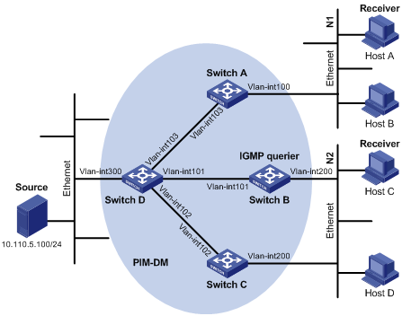
|
Interface |
IP address |
Device |
Interface |
IP address |
|
|
Switch A |
Vlan-int100 |
10.110.1.1/24 |
Switch D |
Vlan-int300 |
10.110.5.1/24 |
|
|
Vlan-int103 |
192.168.1.1/24 |
|
Vlan-int103 |
192.168.1.2/24 |
|
Switch B |
Vlan-int200 |
10.110.2.1/24 |
|
Vlan-int101 |
192.168.2.2/24 |
|
|
Vlan-int101 |
192.168.2.1/24 |
|
Vlan-int102 |
192.168.3.2/24 |
|
Switch C |
Vlan-int200 |
10.110.2.2/24 |
|
|
|
|
|
Vlan-int102 |
192.168.3.1/24 |
|
|
|
Configuration procedure
1) Configure the interface IP addresses and unicast routing protocol for each switch
Configure the IP address and subnet mask for each interface as per Figure 4-7. Detailed configuration steps are omitted here.
Configure the OSPF protocol for interoperation among the switches in the PIM-DM domain. Ensure the network-layer interoperation among Switch A, Switch B, Switch C and Switch D in the PIM-DM domain and enable dynamic update of routing information among the switches through a unicast routing protocol. Detailed configuration steps are omitted here.
2) Enable IP multicast routing, and enable PIM-DM on each interface
# Enable IP multicast routing on Switch A, enable PIM-DM on each interface, and enable IGMP on VLAN-interface 100, which connects Switch A to the stub network.
<SwitchA> system-view
[SwitchA] multicast routing-enable
[SwitchA] interface vlan-interface 100
[SwitchA-Vlan-interface100] igmp enable
[SwitchA-Vlan-interface100] pim dm
[SwitchA-Vlan-interface100] quit
[SwitchA] interface vlan-interface 103
[SwitchA-Vlan-interface103] pim dm
[SwitchA-Vlan-interface103] quit
The configuration on Switch B and Switch C is similar to the configuration on Switch A.
# Enable IP multicast routing on Switch D, and enable PIM-DM on each interface.
<SwitchD> system-view
[SwitchD] multicast routing-enable
[SwitchD] interface vlan-interface 300
[SwitchD-Vlan-interface300] pim dm
[SwitchD-Vlan-interface300] quit
[SwitchD] interface vlan-interface 103
[SwitchD-Vlan-interface103] pim dm
[SwitchD-Vlan-interface103] quit
[SwitchD] interface vlan-interface 101
[SwitchD-Vlan-interface101] pim dm
[SwitchD-Vlan-interface101] quit
[SwitchD] interface vlan-interface 102
[SwitchD-Vlan-interface102] pim dm
[SwitchD-Vlan-interface102] quit
Verifying the configuration
Use the display pim neighbor command to view the PIM neighboring relationships among the switches. For example:
# View the PIM neighboring relationships on Switch D.
[SwitchD] display pim neighbor
Neighbor's Address Interface Name Uptime Expires
192.168.1.1 Vlan-interface1 00:47:08 00:01:39
192.168.2.1 Vlan-interface1 00:48:05 00:01:29
192.168.3.1 Vlan-interface1 00:49:08 00:01:34
Use the display pim routing-table command to view the PIM routing table information on each switch. For example:
# View the PIM routing table information on Switch A.
<SwitchA> display pim routing-table
PIM-DM Routing Table
Total 1 (S,G) entry
(10.110.5.100, 225.1.1.1)
Protocol 0x40: PIMDM, Flag 0xC: SPT NEG_CACHE
Uptime: 00:00:23, Timeout in 187 sec
Upstream interface: Vlan-interface103, RPF neighbor: 192.168.1.2
Downstream interface list:
Vlan-interface100, Protocol 0x1: IGMP, never timeout
Matched 1 (S,G) entry
The information on Switch B and Switch C is similar to that on Switch A.
# View the PIM routing table information on Switch D.
<SwitchD> display pim routing-table
PIM-DM Routing Table
Total 1 (S,G) entry
(10.110.5.100, 225.1.1.1)
Protocol 0x40: PIMDM, Flag 0xC: SPT NEG_CACHE
Uptime: 00:00:23, Timeout in 187 sec
Upstream interface: Vlan-interface300, RPF neighbor: NULL
Downstream interface list:
Vlan-interface101, Protocol 0x200: SPT, timeout in 147 sec
Vlan-interface103, Protocol 0x200: SPT, timeout in 145 sec
Vlan-interface103, Protocol 0x200: SPT, timeout in 145 sec
Matched 1 (S,G) entry
PIM-SM Configuration Example
Network requirements
l Receivers receive VOD information through multicast. The receiver groups of different organizations form stub networks, and one or more receiver hosts exist in each stub network. The entire PIM domain operates in the sparse mode (not divided into different BSR admin-scope regions).
l Host A and Host C are multicast receivers in two stub networks.
l Switch D connects to the network that comprises the multicast source (Source) through VLAN-interface 300.
l Switch A connects to stub network N1 through VLAN-interface 100, and to Switch D and Switch E through VLAN-interface 101 and VLAN-interface 102 respectively.
l Switch B and Switch C connect to stub network N2 through their respective VLAN-interface 200, and to Switch E through VLAN-interface 103 and VLAN-interface 104 respectively.
l Switch E connects to Switch A, Switch B, Switch C and Switch D, and its VLAN-interface 102 interface acts a C-BSR and a C-RP, with the range of multicast groups served by the C-RP being 225.1.1.0/24.
Network diagram
Figure 4-8 Network diagram for PIM-SM domain configuration
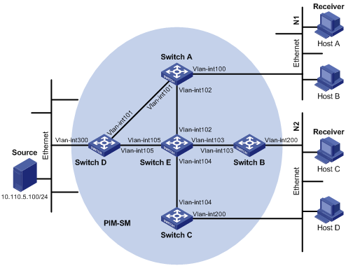
|
Interface |
IP address |
Device |
Interface |
IP address |
|
|
Switch A |
Vlanint100 |
10.110.1.1/24 |
Switch D |
Vlanint300 |
10.110.5.1/24 |
|
|
Vlanint101 |
192.168.1.1/24 |
|
Vlanint101 |
192.168.1.2/24 |
|
|
Vlanint102 |
192.168.9.1/24 |
|
Vlanint105 |
192.168.4.2/24 |
|
Switch B |
Vlanint200 |
10.110.2.1/24 |
Switch E |
Vlanint104 |
192.168.3.2/24 |
|
|
Vlanint103 |
192.168.2.1/24 |
|
Vlanint103 |
192.168.2.2/24 |
|
Switch C |
Vlanint200 |
10.110.2.2/24 |
|
Vlanint102 |
192.168.9.2/24 |
|
|
Vlanint104 |
192.168.3.1/24 |
|
Vlanint105 |
192.168.4.1/24 |
Configuration procedure
1) Configure the interface IP addresses and unicast routing protocol for each switch
Configure the IP address and subnet mask for each interface as per Figure 4-8. Detailed configuration steps are omitted here.
Configure the OSPF protocol for interoperation among the switches in the PIM-SM domain. Ensure the network-layer interoperation among Switch A, Switch B, Switch C, Switch D and Switch E in the PIM-SM domain and enable dynamic update of routing information among the switches through a unicast routing protocol. Detailed configuration steps are omitted here.
2) Enable IP multicast routing, and enable PIM-SM on each interface
# Enable IP multicast routing on Switch A, enable PIM-SM on each interface, and enable IGMP on VLAN-interface 100, which connects Switch A to the stub network.
<SwitchA> system-view
[SwitchA] multicast routing-enable
[SwitchA] interface vlan-interface 100
[SwitchA-Vlan-interface100] igmp enable
SwitchA-Vlan-interface100] pim sm
[SwitchA-Vlan-interface100] quit
[SwitchA] interface vlan-interface 101
[SwitchA-Vlan-interface101] pim sm
[SwitchA-Vlan-interface101] quit
[SwitchA] interface vlan-interface 102
[SwitchA-Vlan-interface102] pim sm
[SwitchA-Vlan-interface102] quit
The configuration on Switch B and Switch C is similar to that on Switch A. The configuration on Switch D and Switch E is also similar to that on Switch A except that it is not necessary to enable IGMP on the corresponding interfaces on these two switches.
3) Configure a C-BSR and a C-RP
# Configure the service scope of RP advertisements and the positions of the C-BSR and C-RP on Switch E.
<SwitchE> system-view
[SwitchE] acl number 2005
[SwitchE-acl-basic-2005] rule permit source 225.1.1.0 0.0.0.255
[SwitchE-acl-basic-2005] quit
[SwitchE] pim
[SwitchE-pim] c-bsr vlan-interface 102 24
[SwitchE-pim] c-rp vlan-interface 102 group-policy 2005
[SwitchE-pim] quit
Verifying the configuration
# Display PIM neighboring relationships on Switch E.
<SwitchE> display pim neighbor
Neighbor's Address Interface Name Uptime Expires
192.168.9.1 Vlan-interface102 02:47:04 00:01:42
192.168.2.1 Vlan-interface103 02:45:04 00:04:46
192.168.3.1 Vlan-interface104 02:42:24 00:04:45
192.168.4.2 Vlan-interface105 02:43:44 00:05:44
# Display BSR information on Switch E.
<SwitchE> display pim bsr-info
Current BSR Address: 192.168.9.2
Priority: 0
Mask Length: 24
Expires: 00:01:39
Local host is BSR
# Display RP information on Switch E.
<SwitchE> display pim rp-info
PIM-SM RP-SET information:
BSR is: 192.168.9.2
Group/MaskLen: 225.1.1.0/24
RP 192.168.9.2
Version: 2
Priority: 0
Uptime: 00:49:44
Expires: 00:01:46
# Display PIM routing table information on Switch A.
<SwitchA> display pim routing-table
PIM-SM Routing Table
Total 1 (S,G) entries, 1 (*,G) entries, 0 (*,*,RP) entry
(*, 225.1.1.1), RP 192.168.9.2
Protocol 0x20: PIMSM, Flag 0x2003: RPT WC NULL_IIF
Uptime: 00:23:21, never timeout
Upstream interface: Vlan-interface102, RPF neighbor: 192.168.9.2
Downstream interface list:
Vlan-interface100, Protocol 0x1: IGMP, never timeout
(10.110.5.100, 225.1.1.1)
Protocol 0x20: PIMSM, Flag 0x80004: SPT
Uptime: 00:03:43, Timeout in 199 sec
Upstream interface: Vlan-interface102, RPF neighbor: 192.168.9.2
Downstream interface list:
Vlan-interface100, Protocol 0x1: IGMP, never timeout
Matched 1 (S,G) entries, 1 (*,G) entries, 0 (*,*,RP) entry
The displayed information of Switch B and Switch C is similar to that of Switch A.
# Display PIM routing table information on Switch D.
<SwitchD> display pim routing-table
PIM-SM Routing Table
Total 1 (S,G) entry, 0 (*,G) entry, 0 (*,*,RP) entry
(10.110.5.100, 225.1.1.1)
Protocol 0x20: PIMSM, Flag 0x4: SPT
Uptime: 00:03:03, Timeout in 27 sec
Upstream interface: Vlan-interface300, RPF neighbor: NULL
Downstream interface list:
Vlan-interface101, Protocol 0x200: SPT, timeout in 147 sec
Vlan-interface105, Protocol 0x200: SPT, timeout in 145 sec
Matched 1 (S,G) entry, 0 (*,G) entry, 0 (*,*,RP) entry
# Display PIM routing table information on Switch E.
<SwitchE> display pim routing-table
PIM-SM Routing Table
Total 1 (S,G) entry, 1 (*,G) entry, 0 (*,*,RP) entry
(*,225.1.1.1), RP 192.168.9.2
Protocol 0x20: PIMSM, Flag 0x2003: RPT WC NULL_IIF
Uptime: 00:02:34, Timeout in 176 sec
Upstream interface: Null, RPF neighbor: 0.0.0.0
Downstream interface list:
Vlan-interface102, Protocol 0x100: RPT, timeout in 176 sec
Vlan-interface103, Protocol 0x100: SPT, timeout in 135 sec
(10.110.5.100, 225.1.1.1)
Protocol 0x20: PIMSM, Flag 0x4: SPT
Uptime: 00:03:03, Timeout in 27 sec
Upstream interface: Vlan-interface105, RPF neighbor: 192.168.4.2
Downstream interface list:
Vlan-interface102, Protocol 0x200: SPT, timeout in 147 sec
Vlan-interface103, Protocol 0x200: SPT, timeout in 145 sec
Matched 1 (S,G) entry, 1 (*,G) entry, 0 (*,*,RP) entry
Troubleshooting PIM
Symptom: The router cannot set up multicast routing tables correctly.
Solution: You can troubleshoot PIM according to the following procedure.
l Make sure that the unicast routing is correct before troubleshooting PIM.
l Because PIM-SM needs the support of RP and BSR, you must execute the display pim bsr-info command to see whether BSR information exists. If not, you must check whether there is any unicast route to the BSR. Then, use the display pim rp-info command to check whether the RP information is correct. If RP information does not exist, you must check whether there is any unicast route to RP.
l Use the display pim neighbor command to check whether the neighboring relationship is correctly established.
When configuring MSDP, go to these sections for information you are interested in:
l Configuring MSDP Basic Functions
l Configuring Connection Between MSDP Peers
l Configuring SA Message Transmission
l Displaying and Maintaining MSDP
l Troubleshooting MSDP Configuration
![]()
l In this manual, the term “router” refers to a router in the generic sense or a Layer 3 Ethernet switch running an IP multicast protocol.
l S3600-SI series Ethernet switches do not support MSDP.
l Because Multicast Source Discovery Protocol (MSDP) does not support the IRF feature, MSDP cannot be configured in Fabric.
MSDP Overview
Introduction to MSDP
In the basic PIM-SM mode, a multicast source registers only with the RP in the local PIM-SM domain, and the multicast source information of a domain is isolated from that of another domain. As a result, the RP is aware of the source information only within the local domain and a multicast distribution tree is built only within the local domain to deliver multicast data from a local multicast source to local receivers. If there is a mechanism that allows RPs of different PIM-SM domains to share their multicast source information, the local RP will be able to join multicast sources in other domains and multicast data can be transmitted among different domains.
MSDP achieves this objective. By establishing MSDP peer relationships among RPs of different PIM-SM domains, source active (SA) messages can be forwarded among domains and the multicast source information can be shared.
![]()
l MSDP is applicable only if the intra-domain multicast protocol is PIM-SM.
l MSDP is meaningful only for the any-source multicast (ASM) model.
How MSDP Works
MSDP peers
With one or more pairs of MSDP peers configured in the network, an MSDP interconnection map is formed, where the RPs of different PIM-SM domains are interconnected in series. Relayed by these MSDP peers, an SA message sent by an RP can be delivered to all other RPs.
Figure 5-1 Where MSDP peers are in the network
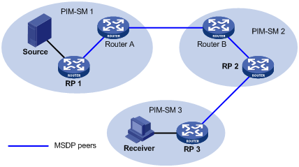
As shown in Figure 5-1 , an MSDP peer can be created on any PIM-SM router. MSDP peers created on PIM-SM routers that assume different roles function differently.
1) MSDP peers on RPs
l Source-side MSDP peer: the MSDP peer nearest to the multicast source (Source), typically the source-side RP, like RP 1. The source-side RP creates SA messages and sends the messages to its remote MSDP peer to notify the MSDP peer of the locally registered multicast source information. A source-side MSDP must be created on the source-side RP; otherwise it will not be able to advertise the multicast source information out of the PIM-SM domain.
l Receiver-side MSDP peer: the MSDP peer nearest to the receivers, typically the source-side RP, like RP 3. Upon receiving an SA message, the receiver-side MSDP peer resolves the multicast source information carried in the message and joins the SPT rooted at the source across the PIM-SM domain. When multicast data from the multicast source arrives, the receiver-side MSDP peer forwards the data to the receivers along the RPT.
l Intermediate MSDP peer: an MSDP peer with multicast remote MSDP peers, like RP 2. An intermediate MSDP peer forwards SA messages received from one remote MSDP peer to other remote MSDP peers, functioning as a relay of multicast source information.
2) MSDP peers created on common PIM-SM routers (other than RPs)
Router A and Router B are MSDP peers on common multicast routers. Such MSDP peers just forward received SA messages.
![]()
An RP is dynamically elected from C-RPs. To enhance network robustness, a PIM-SM network typically has more than one C-RP. As the RP election result is unpredictable, MSDP peering relationships should be built among all C-RPs so that the winner C-RP is always on the "MSDP interconnection map”, while loser C-RPs will assume the role of common PIM-SM routers on the “MSDP interconnection map”.
Implementing inter-domain multicast delivery by leveraging MSDP peers
As shown in Figure 5-2, an active source (Source) exists in the domain PIM-SM 1, and RP 1 has learned the existence of Source through multicast source registration. If RPs in PIM-SM 2 and PIM-SM 3 also wish to know the specific location of Source so that receiver hosts can receive multicast traffic originated from it, MSDP peering relationships should be established between RP 1 and RP 3 and between RP 3 and RP 2 respectively.
Figure 5-2 MSDP peering relationships
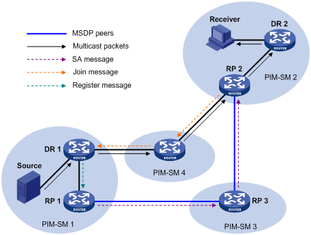
The process if implementing inter-domain multicast delivery by leveraging MSDP peers is as follows:
1) When the multicast source in PIM-SM 1 sends the first multicast packet to multicast group G, DR 1 encapsulates the multicast data within a register message and sends the register message to RP 1. Then, RP 1 gets aware of the information related to the multicast source.
2) As the source-side RP, RP 1 creates SA messages and periodically sends the SA messages to its MSDP peer. An SA message contains the source address (S), the multicast group address (G), and the address of the RP which has created this SA message (namely RP 1).
3) On MSDP peers, each SA message is subject to a Reverse Path Forwarding (RPF) check and multicast policy–based filtering, so that only SA messages that have arrived along the correct path and passed the filtering are received and forwarded. This avoids delivery loops of SA messages. In addition, you can configure MSDP peers into an MSDP mesh group so as to avoid flooding of SA messages between MSDP peers.
4) SA messages are forwarded from one MSDP peer to another, and finally the information of the multicast source traverses all PIM-SM domains with MSDP peers (PIM-SM 2 and PIM-SM 3 in this example).
5) Upon receiving the SA message create by RP 1, RP 2 in PIM-SM 2 checks whether there are any receivers for the multicast group in the domain.
l If so, the RPT for the multicast group G is maintained between RP 2 and the receivers. RP 2 creates an (S, G) entry, and sends an (S, G) join message hop by hop towards DR 1 at the multicast source side, so that it can directly join the SPT rooted at the source over other PIM-SM domains. Then, the multicast data can flow along the SPT to RP 2 and is forwarded by RP 2 to the receivers along the RPT. Upon receiving the multicast traffic, the DR at the receiver side (DR 2) decides whether to initiate an RPT-to-SPT switchover process.
l If no receivers for the group exist in the domain, RP 2 does dot create an (S, G) entry and does join the SPT rooted at the source.
![]()
l An MSDP mesh group refers to a group of MSDP peers that have MSDP peering relationships among one another and share the same group name.
l When using MSDP for inter-domain multicasting, once an RP receives information form a multicast source, it no longer relies on RPs in other PIM-SM domains. The receivers can override the RPs in other domains and directly join the multicast source based SPT.
RPF check rules for SA messages
As shown in Figure 5-3, there are five autonomous systems in the network, AS 1 through AS 5, with IGP enabled on routers within each AS and EBGP as the interoperation protocol among different ASs. Each AS contains at least one PIM-SM domain and each PIM-SM domain contains one ore more RPs. MSDP peering relationships have been established among different RPs. RP 3, RP 4 and RP 5 are in an MSDP mesh group. On RP 7, RP 6 is configured as its static RPF peer.
![]()
If only one MSDP peer exists in a PIM-SM domain, this PIM-SM domain is also called a stub domain. For example, AS 4 in Figure 5-3 is a stub domain. The MSDP peer in a stub domain can have multiple remote MSDP peers at the same time. You can configure one or more remote MSDP peers as static RPF peers. When an RP receives an SA message from a static RPF peer, the RP accepts the SA message and forwards it to other peers without performing an RPF check.
Figure 5-3 Diagram for RPF check for SA messages
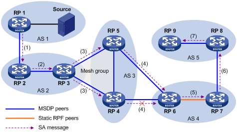
As illustrated in Figure 5-3, these MSDP peers dispose of SA messages according to the following RPF check rules:
1) When RP 2 receives an SA message from RP 1
Because the source-side RP address carried in the SA message is the same as the MSDP peer address, which means that the MSDP peer where the SA is from is the RP that has created the SA message, RP 2 accepts the SA message and forwards it to its other MSDP peer (RP 3).
2) When RP 3 receives the SA message from RP 2
Because the SA message is from an MSDP peer (RP 2) in the same AS, and the MSDP peer is the next hop on the optimal path to the source-side RP, RP 3 accepts the message and forwards it to other peers (RP 4 and RP 5).
3) When RP 4 and RP 5 receive the SA message from RP 3
Because the SA message is from an MSDP peer (RP 3) in the same mesh group, RP 4 and RP 5 both accept the SA message, but they do not forward the message to other members in the mesh group; instead, they forward it to other MSDP peers (RP 6 in this example) out of the mesh group.
4) When RP 6 receives the SA messages from RP 4 and RP 5 (suppose RP 5 has a higher IP address)
Although RP 4 and RP 5 are in the same SA (AS 3) and both are MSDP peers of RP 6, because RP 5 has a higher IP address, RP 6 accepts only the SA message from RP 5.
5) When RP 7 receives the SA message from RP 6
Because the SA message is from a static RPF peer (RP 6), RP 7 accepts the SA message and forwards it to other peer (RP 8).
6) When RP 8 receives the SA message from RP 7
An EBGP route exists between two MSDP peers in different ASs. Because the SA message is from an MSDP peer (RP 7) in a different AS, and the MSDP peer is the next hop on the EBGP route to the source-side RP, RP 8 accepts the message and forwards it to its other peer (RP 9).
7) When RP 9 receives the SA message from RP 8
Because RP 9 has only one MSDP peer, RP 9 accepts the SA message.
SA messages from other paths than described above will not be accepted nor forwarded by MSDP peers.
Implementing intra-domain Anycast RP by leveraging MSDP peers
Anycast RP refers to such an application that enables load balancing and redundancy backup between two or more RPs within a PIM-SM domain by configuring the same IP address for, and establishing MSDP peering relationships between, these RPs.
As shown in Figure 5-4, within a PIM-SM domain, a multicast source sends multicast data to multicast group G, and Receiver is a member of the multicast group. To implement Anycast RP, configure the same IP address (known as anycast RP address, typically a private address) on Router A and Router B, configure these interfaces as C-RPs, and establish an MSDP peering relationship between Router A and Router B.
![]()
Usually an Anycast RP address is configured on a logic interface, like a loopback interface.
Figure 5-4 Typical network diagram of Anycast RP
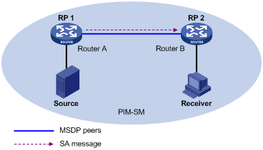
The work process of Anycast RP is as follows:
1) The multicast source registers with the nearest RP. In this example, Source registers with RP 1, with its multicast data encapsulated in the register message. When the register message arrives to RP 1, RP 1 decapsulates the message.
2) Receivers send join messages to the nearest RP to join in the RPT rooted as this RP. In this example, Receiver joins the RPT rooted at RP 2.
3) RPs share the registered multicast information by means of SA messages. In this example, RP 1 creates an SA message and sends it to RP 2, with the multicast data from Source encapsulated in the SA message. When the SA message reaches RP 2, RP 2 decapsulates the message.
4) Receivers receive the multicast data along the RPT and directly join the SPT rooted at the multicast source. In this example, RP 2 forwards the multicast data down the RPT. When Receiver receives the multicast data from Source, it directly joins the SPT rooted at Source.
The significance of Anycast RP is as follows:
l Optimal RP path: A multicast source registers with the nearest RP so that an SPT with the optimal path is built; a receiver joins the nearest RP so that an RPT with the optimal path is built.
l Load balancing between RPs: Each RP just needs to maintain part of the source/group information within the PIM-SM domain and forward part of the multicast data, thus achieving load balancing between different RPs.
l Redundancy backup between RPs: When an RP fails, the multicast source previously registered on it or the receivers previous joined it will register with or join another nearest RP, thus achieving redundancy backup between RPs.
![]()
l Be sure to configure a 32-bit subnet mask (255.255.255.255) for the Anycast RP address, namely configure the Anycast RP address into a host address.
l An MSDP peer address must be different from the Anycast RP address.
Protocols and Standards
MSDP is documented in the following specifications:
l RFC 3618: Multicast Source Discovery Protocol (MSDP)
l RFC 3446: Anycast Rendezvous Point (RP) mechanism using Protocol Independent Multicast (PIM) and Multicast Source Discovery Protocol (MSDP)
Configuring MSDP Basic Functions
A route is required between two routers that are MSDP peers to each other. Through this route, the two routers can transfer SA messages between PIM-SM domains. For an area containing only one MSDP peer, known as a stub area, the route is not compulsory. SA messages are transferred in a stub area through the configuration of static RPF peers. In addition, the use of static RPF peers can avoid RPF check on the received SA messages, thus saving resources.
When configuring multiple static RPF peers for the same router, you must follow the following two configuration methods:
l In the case that all the peers use the rp-policy keyword: Multiple static RPF peers function at the same time. RPs in SA messages are filtered based on the configured prefix list, and only the SA messages whose RP addresses pass the filtering are received. If multiple static RPF peers using the same rp-policy keyword are configured, when any of the peers receives an SA message, it will forward the SA message to other peers.
l None of the peers use the rp-policy keyword: Based on the configured sequence, only the first static RPF peer whose connection state is UP is active. All the SA messages from this peer will be received, while the SA messages from other static RPF peers will be discarded. Once the active static RPF peer fails (because the configuration is removed or the connection is terminated), based on the configuration sequence, the subsequent first static RPF peer whose connection is in the UP state will be selected as the active static RPF peer.
Configuration Prerequisites
Before configuring basic MSDP functions, you need to configure:
l A unicast routing protocol
Configuring MSDP Basic Functions
Follow these steps to configure MSDP basic functions:
|
To do... |
Use the command... |
Remarks |
|
Enter system view |
system-view |
— |
|
Enable MSDP function and enter MSDP view |
msdp |
Required Disabled by default |
|
Create an MSDP peer connection |
peer peer-address connect-interface interface-type interface-number |
Required No MSDP peer connection is created by default. |
|
Configure a static RPF peer |
static-rpf-peer peer-address [ rp-policy ip-prefix-name ] |
Optional No static RFP is configured by default. |
Configuring Connection Between MSDP Peers
An AS may contain multiple MSDP peers. To avoid SA flooding between the MSDP peers, you can use the MSDP mesh mechanism to improve traffic. When multiple MSDP peers are fully connected with one another, these MSDP peers form a mesh group.
When an MSDP peer in the mesh group receives SA messages from outside the mesh group, it sends them to other members of the group. On the other hand, a mesh group member does not perform RPF check on SA messages from within the mesh group and does not forward the messages to other members of the mesh group. This avoids SA message flooding since it is unnecessary to run BGP or MBGP between MSDP peers, thus simplifying the RPF checking mechanism.
Configuration Prerequisites
Before configuring an MSDP peer connection, you need to configure:
l A unicast routing protocol
l Basic functions of IP multicast
l PIM-SM basic functions
Complete the following tasks to configure an MSDP peer connection:
|
Task |
Remarks |
|
Optional |
|
|
Optional |
|
|
Optional |
Configuring Description Information for MSDP Peers
You can configure description information for each MSDP peer to manage and memorize the MSDP peers.
Follow these steps to configure description information for an MSDP peer:
|
To do... |
Use the command... |
Remarks |
|
Enter system view |
system-view |
— |
|
Enter MSDP view |
msdp |
— |
|
Configure description information for an MSDP peer |
peer peer-address description text |
Optional By default, an MSDP peer has no description information. |
Configuring an MSDP Mesh Group
Configure a mesh group name on all the peers that will become members of the MSDP mesh group so that the peers are fully connected with one another in the mesh group.
Follow these steps to configure an MSDP mesh group:
|
To do... |
Use the command... |
Remarks |
|
Enter system view |
system-view |
— |
|
Enter MSDP view |
msdp |
— |
|
Add an MSDP peer to a mesh group |
peer peer-address mesh-group name |
Required By default, an MSDP peer does not belong to any mesh group. |
![]()
l Before you configure an MSDP mesh group, make sure that the routers are fully connected with one another.
l The same group name must be configured on all the peers before they can join a mesh group.
l If you add the same MSDP peer to multiple mesh groups, only the latest configuration takes effect.
Configuring MSDP Peer Connection Control
Follow these steps to configure MSDP peer connection control:
|
To do... |
Use the command... |
Remarks |
|
Enter system view |
system-view |
— |
|
Enter MSDP view |
msdp |
— |
|
Shut down the connection with the specified MSDP peer |
shutdown peer-address |
Optional By default, all MSDP peering connections are up. |
|
Configure the retry interval of MSDP peer connection establishment |
timer retry seconds |
Optional 30 seconds by default |
Configuring SA Message Transmission
An SA message contains the IP address of the multicast source S, multicast group address G, and RP address. In addition, it contains the first multicast data received by the RP in the domain where the multicast source resides. For some burst multicast data, if the multicast data interval exceeds the SA message hold time, the multicast data must be encapsulated in the SA message; otherwise, the receiver will never receive the multicast source information.
By default, when a new receiver joins, a router does not send any SA request message to its MSDP peer but has to wait for the next SA message. This defers the reception of the multicast information by the receiver. In order for the new receiver to know about the currently active multicast source as quickly as possible, the router needs to send SA request messages to the MSDP peer.
Generally, a router accepts all SA messages sent by all MSDP peers and sends all SA messages to all MSDP peers. By configuring the rules for filtering SA messages to receive/send, you can effectively control the transmission of SA messages among MSDP peers. For forwarded SA messages, you can also configure a Time-to-Live (TTL) threshold to control the range where SA messages carrying encapsulated data are transmitted.
Configuration Prerequisites
Before you configure SA message transmission, perform the following tasks:
l Configuring a unicast routing protocol.
l Configuring basic IP multicast functions.
l Configuring basic PIM-SM functions.
l Configuring basic MSDP functions.
Complete the following tasks to configure SA message transmission:
|
Task |
Remarks |
|
Optional |
|
|
Optional |
|
|
Configuring the Transmission and Filtering of SA Request Messages |
Optional |
|
Configuring a Rule for Filtering the Multicast Sources of SA Messages |
Optional |
|
Configuring a Rule for Filtering Received and Forwarded SA Messages |
Optional |
Configuring RP Address in SA Messages
MSDP peers deliver SA messages to one another. Upon receiving an SA message, a router performs an RPF check on the message. If the router finds that the remote RP address is the same as the local RP address, it will discard the SA message. In anycast RP application, however, you need to configure RPs with the same IP address on two or more routers in the same PIM-SM domain, and configure these RPs as MSDP peers to one another. Therefore, a logic RP address (namely the RP address on a logic interface) that is different from the actual RP address must be designated for SA messages so that the messages can pass the RPF check.
Follow these steps to configure RP address in SA messages:
|
To do... |
Use the command... |
Remarks |
|
Enter system view |
system-view |
— |
|
Enter MSDP view |
msdp |
— |
|
Configure the address of the specified interface as the RP address in SA messages |
originating-rp interface-type interface-number |
Required By default, the RP address in SA messages is the RP address configured for PIM. |
![]()
In Anycast RP application, a C-BSR and a C-RP must be configured on different devices or ports.
Configuring SA Message Cache
You can configure the number of SA entries cached in each MSDP peer on the router by executing the following command, but the number must be within the system limit. To protect a router against Denial of Service (DoS) attacks, you can manually configure the maximum number of SA messages cached on the router. Generally, the configured number of SA messages cached should be less than the system limit.
Follow these steps to configure SA message cache:
|
To do... |
Use the command... |
Remarks |
|
Enter system view |
system-view |
— |
|
Enter MSDP view |
msdp |
— |
|
Enable SA message caching mechanism |
cache-sa-enable |
Optional Enabled by default |
|
Configure the maximum number of SA messages that can be cached |
peer peer-address sa-cache-maximum sa-limit |
Optional The default is 2,048. |
Configuring the Transmission and Filtering of SA Request Messages
After you enable the sending of SA request messages, when a router receives a Join message, it sends an SA request message to the specified remote MSDP peer, which responds with an SA message that it has cached. After sending an SA request message, the router will get immediately a response from all active multicast sources. The SA message that the remote MSDP peer sends in response is cached in advance; therefore, you must enable the SA message caching mechanism in advance. Typically, only the routers caching SA messages can respond to SA request messages.
After you have configured a rule for filtering received SA messages, if no ACL is specified, all SA request messages sent by the corresponding MSDP peer will be ignored; if an ACL is specified, the SA request messages that satisfy the ACL rule are received while others are ignored.
Follow these steps to configure the transmission and filtering of SA request messages:
|
To do... |
Use the command... |
Remarks |
|
Enter system view |
system-view |
— |
|
Enter MSDP view |
msdp |
— |
|
Enable SA message caching mechanism |
cache-sa-enable |
Optional By default, the router caches the SA state upon receipt of an SA message. |
|
Enable MSDP peers to send SA request messages |
peer peer-address request-sa-enable |
Optional By default, upon receipt of a Join message, the router sends no SA request message to its MSDP peer but waits for the next SA message. |
|
Configure a rule for filtering the SA messages received by an MSDP peer |
peer peer-address sa-request-policy [ acl acl-number ] |
Optional By default, a router receives all SA request messages from the MSDP peer. |
Configuring a Rule for Filtering the Multicast Sources of SA Messages
An RP filters each registered source to control the information of active sources advertised in the SA message. An MSDP peer can be configured to advertise only the (S, G) entries in the multicast routing table that satisfy the filtering rule when the MSDP creates the SA message; that is, to control the (S, G) entries to be imported from the multicast routing table to the PIM-SM domain. If the import-source command is executed without the acl keyword, no source will be advertised in the SA message.
Follow these steps to configure a rule for filtering multicast sources using SA messages:
|
To do... |
Use the command... |
Remarks |
|
Enter system view |
system-view |
— |
|
Enter MSDP view |
msdp |
— |
|
Configure to filter multicast sources using SA messages |
import-source [ acl acl-number ] |
Optional By default, all the (S, G) entries in the domain are advertised in the SA message. |
Configuring a Rule for Filtering Received and Forwarded SA Messages
Besides the creation of source information, controlling multicast source information allows you to control the forwarding and reception of source information. You can control the reception of SA messages using the MSDP inbound filter (corresponding to the import keyword); you can control the forwarding of SA messages by using either the MSDP outbound filter (corresponding to the export argument) or the TTL threshold. MSDP inbound/outbound filter implements the following functions:
l Filtering out all (S, G) entries
l Receiving/forwarding only the SA messages permitted by advanced ACL rules (You can configure ACL rules for filtering source IP addresses and group IP addresses.)
An SA message carrying encapsulated data can reach the specified MSDP peer outside the domain only if the TTL in its IP header is greater than the threshold; therefore, you can control the forwarding range of SA messages that carry encapsulated data by configuring the TTL threshold.
Follow these steps to configure a rule for filtering received and forwarded SA messages:
|
To do... |
Use the command... |
Remarks |
|
Enter system view |
system-view |
— |
|
Enter MSDP view |
msdp |
— |
|
Configure to filter imported and exported SA messages |
peer peer-address sa-policy { import | export } [ acl acl-number ] |
Optional By default, no filtering is imposed on SA messages to be received or forwarded, namely all SA messages from MSDP peers are received or forwarded. |
|
Configure the minimum TTL required for a multicast packet to be sent to the specified MSDP peer |
peer peer-address minimum-ttl ttl-value |
Optional By default, the value of TTL threshold is 0. |
Displaying and Maintaining MSDP
Displaying and maintaining MSDP
|
To do... |
Use the command... |
Remarks |
|
Display the brief information of MSDP peer state |
display msdp brief |
Available in any view |
|
Display the detailed information of MSDP peer status |
display msdp peer-status [ peer-address ] |
Available in any view |
|
Display the (S, G) state learned from MSDP peers |
display msdp sa-cache [ group-address | source-address | as-number ] * |
Available in any view |
|
Display the number of sources and groups in the MSDP cache |
display msdp sa-count [autonomous-system-number ] |
Available in any view |
|
Reset the TCP connection with the specified MSDP peer |
reset msdp peer peer-address |
Available in user view |
|
Clear the cached SA messages |
reset msdp sa-cache [ group-address ] |
Available in user view |
|
Clear the statistics information of the specified MSDP peer without resetting the MSDP peer |
reset msdp statistics [ peer-address ] |
Available in user view |
Tracing the transmission path of an SA message over the network
Follow these steps to trace the transmission path of an SA message over the network:
|
To do... |
Use the command... |
Remarks |
|
Trace the transmission path of an SA message over the network |
msdp-tracert source-address group-address rp-address [ max-hops max-hops ] [ next-hop-info | sa-info | peer-info ]* [ skip-hops skip-hops ] |
You can execute the msdp-tracert command in any view. |
|
Trace the transmission path of messages sent by the multicast source over the network |
mtracert source-address [ group-address | last-hop-router-address group-address ] |
You can execute the mtracert command in any view. |
MSDP Configuration Example
Anycast RP Configuration
Network requirements
l The PIM-SM domain has multiple multicast sources and receivers. OSPF runs within the domain to provide unicast routes.
l It is required to configure the anycast RP feature so that the receiver-side DRs and the source-side DRs can initiate a Join message to their respective RPs that are the topologically nearest to them.
l On Switch B and Switch D, configure the interface Loopback 10 as a C-BSR, and Loopback 20 as a C-RP.
l The router ID of Switch B is 1.1.1.1, while the router ID of Switch D is 2.2.2.2. Set up an MSDP peering relationship between Switch B and Switch D.
Network diagram
Figure 5-5 Network diagram for anycast RP configuration
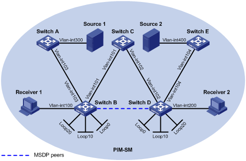
|
Device |
Interface |
IP address |
Device |
Interface |
IP address |
|
Source 1 |
— |
10.110.5.100/24 |
Switch C |
Vlan-int101 |
192.168.1.2/24 |
|
Source 2 |
— |
10.110.6.100/24 |
|
Vlan-int102 |
192.168.2.2/24 |
|
Switch A |
Vlan-int300 |
10.110.5.1/24 |
Switch D |
Vlan-int200 |
10.110.3.1/24 |
|
|
Vlan-int103 |
10.110.2.2/24 |
|
Vlan-int104 |
10.110.4.1/24 |
|
Switch B |
Vlan-int100 |
10.110.1.1/24 |
|
Vlan-int102 |
192.168.2.1/24 |
|
|
Vlan-int103 |
10.110.2.1/24 |
|
Loop0 |
2.2.2.2/32 |
|
|
Vlan-int101 |
192.168.1.1/24 |
|
Loop10 |
4.4.4.4/32 |
|
|
Loop0 |
1.1.1.1/32 |
|
Loop20 |
10.1.1.1/32 |
|
|
Loop10 |
3.3.3.3/32 |
Switch E |
Vlan-int400 |
10.110.6.1/24 |
|
|
Loop20 |
10.1.1.1/32 |
|
Vlan-int104 |
10.110.4.2/24 |
Configuration procedure
1) Configure the interface IP addresses and unicast routing protocol for each switch
Configure the IP address and subnet mask for each interface as per Figure 5-5. Detailed configuration steps are omitted here.
Configure OSPF for interconnection between the switches. Ensure the network-layer interoperation among the switches, and ensure the dynamic update of routing information between the switches through a unicast routing protocol. Detailed configuration steps are omitted here.
2) Enable IP multicast routing, and enable PIM-SM and IGMP
# Enable IP multicast routing on Switch B, enable PIM-SM on each interface, and enable IGMP on the host-side interface VLAN-interface 100.
<SwitchB> system-view
[SwitchB] multicast routing-enable
[SwitchB] interface vlan-interface 100
[SwitchB-Vlan-interface100] igmp enable
[SwitchB-Vlan-interface100] pim sm
[SwitchB-Vlan-interface100] quit
[SwitchB] interface vlan-interface 103
[SwitchB-Vlan-interface103] pim sm
[SwitchB-Vlan-interface103] quit
[SwitchB] interface Vlan-interface 101
[SwitchB-Vlan-interface101] pim sm
[SwitchB-Vlan-interface101] quit
[SwitchB] interface loopback 0
[SwitchB-LoopBack0] pim sm
[SwitchB-LoopBack0] quit
[SwitchB] interface loopback 10
[SwitchB-LoopBack10] pim sm
[SwitchB-LoopBack10] quit
[SwitchB] interface loopback 20
[SwitchB-LoopBack20] pim sm
[SwitchB-LoopBack20] quit
The configuration on Switch A, Switch C, Switch D, and Switch E is similar to the configuration on Switch B.
3) Configure C-BSRs and C-RPs.
# Configure Loopback 10 as a C-BSR and configure Loopback 20 as a C-RP on Switch B.
[SwitchB] pim
[SwitchB-pim] c-bsr loopback 10 24
[SwitchB-pim] c-rp loopback 20
[SwitchB-pim] quit
The configuration on Switch D is similar to the configuration on Switch B.
4) Configure MSDP peers
# Configure an MSDP peer on Loopback 0 of Switch B.
[SwitchB] msdp
[SwitchB-msdp] originating-rp loopback 0
[SwitchB-msdp] peer 2.2.2.2 connect-interface loopback 0
[SwitchB-msdp] quit
# Configure an MSDP peer on Loopback 0 of Switch D.
[SwitchD] msdp
[SwitchD-msdp] originating-rp loopback 0
[SwitchD-msdp] peer 1.1.1.1 connect-interface loopback 0
[SwitchD-msdp] quit
5) Verify the configuration
You can use the display msdp brief command to view the brief information of MSDP peering relationships between the switches.
# View the brief MSDP peer information on Switch B.
[SwitchB] display msdp brief
MSDP Peer Brief Information
Peer's Address State Up/Down time AS SA Count Reset Count
2.2.2.2 Up 00:48:21 ? 2 0
# View the brief MSDP peer information on Switch D.
[SwitchD] display msdp brief
MSDP Peer Brief Information
Peer's Address State Up/Down time AS SA Count Reset Count
1.1.1.1 Up 00:50:22 ? 2 0
When Source 1 (10.110.5.100/24) sends multicast data to multicast group G (225.1.1.1), Receiver 1 joins multicast group G. By comparing the PIM routing information displayed on Switch B with that displayed on Switch D, you can see that Switch B now acts as the RP for Source 1 and Receiver 1. Source 1 registers with Switch B and Receiver 1 sends a join message to Switch B.
# View the PIM routing information on Switch B.
[Switch B] display pim routing-table
PIM-SM Routing Table
Total 1 (S,G) entry, 1 (*,G) entry, 0 (*,*,RP) entry
(*, 225.1.1.1), RP 10.1.1.1
Protocol 0x20: PIMSM, Flag 0x2003: RPT WC NULL_IIF
Uptime: 00:00:13, never timeout
Upstream interface: Null, RPF neighbor: 0.0.0.0
Downstream interface list:
Vlan-interface100, Protocol 0x1: IGMP, never timeout
(10.110.5.100, 225.1.1.1)
Protocol 0x20: PIMSM, Flag 0x4: SPT
Uptime: 00:03:08, Timeout in 206 sec
Upstream interface: Vlan-interface103, RPF neighbor: NULL
Downstream interface list:
Vlan-interface100, Protocol 0x1: IGMP, never timeout
Matched 1 (S,G) entry, 1 (*,G) entry, 0 (*,*,RP) entry
# View the PIM routing information on Switch D.
[SwitchD] display pim routing-table
PIM-SM Routing Table
Total 0 (S,G) entry, 0 (*,G) entry, 0 (*,*,RP) entry
Matched 0 (S,G) entry, 0 (*,G) entry, 0 (*,*,RP) entry
Troubleshooting MSDP Configuration
MSDP Peer Always in the Down State
Symptom
An MSDP peer is configured, but it is always in the down state.
Analysis
An MSDP peer relationship between the locally configured connect-interface interface address and the configured peer address is based on a TCP connection. If the address of local connect-interface interface is inconsistent with the peer address configured on the peer router, no TCP connection can be established. If there is no route between the two peers, no TCP connection can be established.
Solution
1) Check the connectivity of the route between the routers. Use the display ip routing-table command to check that the unicast route between the routers is correct.
2) Further check that a unicast route exists between two routers that will become MSDP peers and that the route leads to the two peers.
No SA Entry in the SA Cache of the Router
Symptom
An MSDP fails to send (S, G) forwarding entries through an SA message.
Analysis
You can use the import-source command to send the (S, G) entries of the local multicast domain to the neighboring MSDP peer through SA messages. The acl keyword is optional. If you do not use this keyword, all (S, G) entries will be filtered out by default, that is, none of the (S, G) entries in the local multicast domain will be advertised. Before the import-source command is executed, the system will send all (S, G) entries in the local multicast domain. If the MSDP fails to send the (S, G) entries of the local multicast domain through SA messages, verify that the import-source command is configured correctly.
Solution
1) Check the connectivity of the route between the routers. Use the display ip routing-table command to check that the unicast route between the routers is correct.
2) Further check that a unicast route exists between two routers that will become MSDP peers and that the route leads to the two peers.
3) Verify the configuration of the import-source command and the corresponding ACL to ensure that the ACL rule filters the right (S, G) entries.
When configuring IGMP snooping, go to these sections for information you are interested in:
l Displaying and Maintaining IGMP Snooping
l IGMP Snooping Configuration Examples
l Troubleshooting IGMP Snooping
![]()
In this manual, the term “router” refers to a router in the generic sense or a Layer 3 Ethernet switch running an IP multicast protocol.
IGMP Snooping Overview
Internet Group Management Protocol Snooping (IGMP Snooping) is a multicast constraining mechanism that runs on Layer 2 devices to manage and control multicast groups.
Principle of IGMP Snooping
By analyzing received IGMP messages, a Layer 2 device running IGMP Snooping establishes mappings between ports and multicast MAC addresses and forwards multicast data based on these mappings.
As shown in Figure 6-1, when IGMP Snooping is not running on the switch, multicast packets are broadcast to all devices at Layer 2. When IGMP Snooping is running on the switch, multicast packets for known multicast groups are multicast to the receivers, rather than broadcast to all hosts, at Layer 2. However, multicast packets for unknown multicast groups are still broadcast at Layer 2.
Figure 6-1 Before and after IGMP Snooping is enabled on Layer 2 device
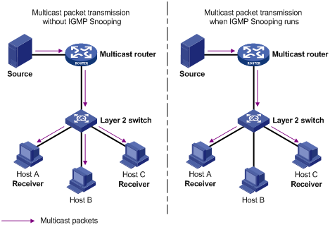
Basic Concepts in IGMP Snooping
IGMP Snooping related ports
As shown in Figure 6-2, Router A connects to the multicast source, IGMP Snooping runs on Switch A and Switch B, Host A and Host C are receiver hosts (namely, multicast group members).
Figure 6-2 IGMP Snooping related ports
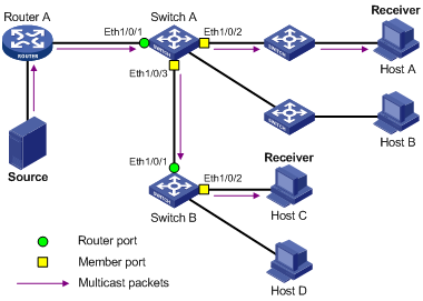
Ports involved in IGMP Snooping, as shown in Figure 6-2, are described as follows:
l Router port: A router port is a port on the Layer 3 multicast device (DR or IGMP querier) side of the Ethernet switch. In the figure, Ethernet 1/0/1 of Switch A and Ethernet 1/0/1 of Switch B are router ports. A switch registers all its local router ports in its router port list.
l Member port: A member port is a port on the multicast group member side of the Ethernet switch. In the figure, Ethernet 1/0/2 and Ethernet 1/0/3 of Switch A and Ethernet 1/0/2 of Switch B are member ports. The switch records all member ports on the local device in the IGMP Snooping forwarding table.
Port aging timers in IGMP Snooping and related messages and actions
Table 6-1 Port aging timers in IGMP Snooping and related messages and actions
|
Timer |
Description |
Message before expiry |
Action after expiry |
|
Router port aging timer |
For each router port, the switch sets a timer initialized to the aging time of the route port |
IGMP general query or PIM hello |
The switch removes this port from its router port list |
|
Member port aging timer |
When a port joins a multicast group, the switch sets a timer for the port, which is initialized to the member port aging time |
IGMP membership report |
The switch removes this port from the multicast group forwarding table |
Work Mechanism of IGMP Snooping
A switch running IGMP Snooping performs different actions when it receives different IGMP messages, as follows:
When receiving a general query
The IGMP querier periodically sends IGMP general queries to all hosts and routers on the local subnet to find out whether active multicast group members exist on the subnet.
Upon receiving an IGMP general query, the switch forwards it through all ports in the VLAN except the receiving port and performs the following to the receiving port:
l If the receiving port is a router port existing in its router port list, the switch resets the aging timer of this router port.
l If the receiving port is not a router port existing in its router port list, the switch adds it into its router port list and sets an aging timer for this router port.
When receiving a membership report
A host sends an IGMP report to the multicast router in the following circumstances:
l Upon receiving an IGMP query, a multicast group member host responds with an IGMP report.
l When intended to join a multicast group, a host sends an IGMP report to the multicast router to announce that it is interested in the multicast information addressed to that group.
Upon receiving an IGMP report, the switch forwards it through all the router ports in the VLAN, resolves the address of the multicast group the host is interested in, and performs the following to the receiving port:
l If the port is already in the forwarding table, the switch resets the member port aging timer of the port.
l If the port is not in the forwarding table, the switch installs an entry for this port in the forwarding table and starts the member port aging timer of this port.
![]()
A switch will not forward an IGMP report through a non-router port for the following reason: Due to the IGMP report suppression mechanism, if member hosts of that multicast group still exist under non-router ports, the hosts will stop sending reports when they receive the message, and this prevents the switch from knowing if members of that multicast group are still attached to these ports.
For the description of IGMP report suppression mechanism, refer to Work Mechanism of IGMPv1.
When receiving a leave message
When an IGMPv1 host leaves a multicast group, the host does not send an IGMP leave message, so the switch cannot know immediately that the host has left the multicast group. However, as the host stops sending IGMP reports as soon as it leaves a multicast group, the switch deletes the forwarding entry for the member port corresponding to the host from the forwarding table when its aging timer expires.
When an IGMPv2 or IGMPv3 host leaves a multicast group, the host sends an IGMP leave message to the multicast router to announce that it has leaf the multicast group.
Upon receiving an IGMP leave message on the last member port, a switch forwards it out all router ports in the VLAN. Because the switch does not know whether any other member hosts of that multicast group still exists under the port to which the IGMP leave message arrived, the switch does not immediately delete the forwarding entry corresponding to that port from the forwarding table; instead, it resets the aging timer of the member port.
Upon receiving the IGMP leave message from a host, the IGMP querier resolves from the message the address of the multicast group that the host just left and sends an IGMP group-specific query to that multicast group through the port that received the leave message. Upon receiving the IGMP group-specific query, a switch forwards it through all the router ports in the VLAN and all member ports of that multicast group, and performs the following to the receiving port:
l If any IGMP report in response to the group-specific query arrives to the member port before its aging timer expires, this means that some other members of that multicast group still exist under that port: the switch resets the aging timer of the member port.
l If no IGMP report in response to the group-specific query arrives to the member port before its aging timer expires as a response to the IGMP group-specific query, this means that no members of that multicast group still exist under the port: the switch deletes the forwarding entry corresponding to the port from the forwarding table when the aging timer expires.
![]()
After an Ethernet switch enables IGMP Snooping, when it receives the IGMP leave message sent by a host in a multicast group, it judges whether the multicast group exists automatically. If the multicast group does not exist, the switch drops this IGMP leave message.
Configuring IGMP Snooping
Complete the following tasks to configure IGMP Snooping:
|
Task |
Remarks |
|
Required |
|
|
Optional |
|
|
Optional |
|
|
Optional |
|
|
Optional |
|
|
Configuring the Maximum Number of Multicast Groups on a Port |
Optional |
|
Optional |
|
|
Optional |
|
|
Optional |
|
|
Optional |
|
|
Optional |
|
|
Optional |
|
|
Optional |
Enabling IGMP Snooping
Follow these steps to enable IGMP Snooping:
|
To do... |
Use the command... |
Remarks |
|
Enter system view |
system-view |
— |
|
Enable IGMP Snooping globally |
igmp-snooping enable |
Required By default, IGMP Snooping is disabled globally. |
|
Enter VLAN view |
vlan vlan-id |
— |
|
Enable IGMP Snooping on the VLAN |
igmp-snooping enable |
Required By default, IGMP Snooping is disabled on all the VLANs. |
![]()
l Although both Layer 2 and Layer 3 multicast protocols can run on the same switch simultaneously, they cannot run simultaneously on a VLAN or its corresponding VLAN interface.
l Before enabling IGMP Snooping in a VLAN, be sure to enable IGMP Snooping globally in system view; otherwise the IGMP Snooping settings will not take effect.
l If IGMP Snooping and VLAN VPN are enabled on a VLAN at the same time, IGMP queries are likely to fail to pass the VLAN. You can solve this problem by configuring VLAN tags for queries. For details, see Configuring a VLAN Tag for Query Messages.
Configuring the Version of IGMP Snooping
With the development of multicast technologies, IGMPv3 has found increasingly wide application. In IGMPv3, a host can not only join a specific multicast group but also explicitly specify to receive or reject the information from a specific multicast source. Working with PIM-SSM, IGMPv3 enables hosts to join specific multicast sources and groups directly, greatly simplifying multicast routing protocols and optimizing the network topology.
Follow these steps to configure the version of IGMP Snooping:
|
To do... |
Use the command... |
Remarks |
|
Enter system view |
system-view |
— |
|
Enter VLAN view |
vlan vlan-id |
— |
|
Configure the version of IGMP Snooping |
igmp-snooping version version-number |
Optional The default IGMP Snooping version is version 2. |
![]()
l Before configuring related IGMP Snooping functions, you must enable IGMP Snooping in the specified VLAN.
l Different multicast group addresses should be configured for different multicast sources because IGMPv3 Snooping cannot distinguish multicast data from different sources to the same multicast group.
Configuring Timers
This section describes how to configure the aging timer of the router port, the aging timer of the multicast member ports, and the query response timer.
Follow these steps to configure timers:
|
To do... |
Use the command... |
Remarks |
|
Enter system view |
system-view |
— |
|
Configure the aging timer of the router port |
igmp-snooping router-aging-time seconds |
Optional By default, the aging time of the router port is 105 seconds. |
|
Configure the general query response timer |
igmp-snooping max-response-time seconds |
Optional By default, the general query response timeout time is 10 seconds. |
|
Configure the aging timer of the multicast member port |
igmp-snooping host-aging-time seconds |
Optional By default, the aging time of multicast member ports is 260 seconds |
Configuring Fast Leave Processing
With fast leave processing enabled, when the switch receives an IGMP leave message on a port, the switch directly removes that port from the forwarding table entry for the specific group. If only one host is attached to the port, enable fast leave processing to improve bandwidth management.
Enabling fast leave processing in system view
Follow these steps to enable fast leave processing in system view:
|
To do... |
Use the command... |
Remarks |
|
Enter system view |
system-view |
— |
|
Enable fast leave processing |
igmp-snooping fast-leave [ vlan vlan-list ] |
Required By default, the fast leave processing feature is disabled. |
Enabling fast leave processing in Ethernet port view
Follow these steps to enable fast leave processing in Ethernet view:
|
To do... |
Use the command... |
Remarks |
|
Enter system view |
system-view |
— |
|
Enter Ethernet port view |
interface interface-type interface-number |
— |
|
Enable fast leave processing for specific VLANs |
igmp-snooping fast-leave [ vlan vlan-list ] |
Required By default, the fast leave processing feature is disabled. |
![]()
l The fast leave processing function works for a port only if the host attached to the port runs IGMPv2 or IGMPv3.
l The configuration performed in system view takes effect on all ports of the switch if no VLAN is specified; if one or more VLANs are specified, the configuration takes effect on all ports in the specified VLAN(s).
l The configuration performed in Ethernet port view takes effect on the port no matter which VLAN it belongs to if no VLAN is specified; if one or more VLANs are specified, the configuration takes effect on the port only if the port belongs to the specified VLAN(s).
l If fast leave processing and unknown multicast packet dropping or non-flooding are enabled on a port to which more than one host is connected, when one host leaves a multicast group, the other hosts connected to port and interested in the same multicast group will fail to receive multicast data for that group.
Configuring a Multicast Group Filter
On an IGMP Snooping-enabled switch, the configuration of a multicast group allows the service provider to define restrictions on multicast programs available to different users.
In an actual application, when a user requests a multicast program, the user’s host initiates an IGMP report. Upon receiving this report message, the switch checks the report against the ACL rule configured on the receiving port. If the receiving port can join this multicast group, the switch adds this port to the IGMP Snooping multicast group list; otherwise the switch drops this report message. Any multicast data that has failed the ACL check will not be sent to this port. In this way, the service provider can control the VOD programs provided for multicast users.
Make sure that an ACL rule has been configured before configuring this feature.
Configuring a multicast group filter in system view
Follow these steps to configure a multicast group filter in system view:
|
To do... |
Use the command... |
Remarks |
|
Enter system view |
system-view |
— |
|
Configure a multicast group filter |
igmp-snooping group-policy acl-number [ vlan vlan-list ] |
Required No group filter is configured by default, namely hosts can join any multicast group. |
Configuring a multicast group filter in Ethernet port view
Follow these steps to configure a multicast group filter in Ethernet port view:
|
To do... |
Use the command... |
Remarks |
|
Enter system view |
system-view |
— |
|
Enter Ethernet port view |
interface interface-type interface-number |
— |
|
Configure a multicast group filter |
igmp-snooping group-policy acl-number [ vlan vlan-list ] |
Optional No group filter is configured by default, namely hosts can join any multicast group. |
![]()
l A port can belong to multiple VLANs, you can configure only one ACL rule per VLAN on a port.
l If no ACL rule is configured, all the multicast groups will be filtered.
l Since most devices broadcast unknown multicast packets by default, this function is often used together with the function of dropping unknown multicast packets to prevent multicast streams from being broadcast as unknown multicast packets to a port blocked by this function.
l The configuration performed in system view takes effect on all ports of the switch if no VLAN is specified; if one or more VLANs are specified, the configuration takes effect on all ports in the specified VLAN(s).
l The configuration performed in Ethernet port view takes effect on the port no matter which VLAN it belongs to if no VLAN is specified; if one or more VLANs are specified, the configuration takes effect on the port only if the port belongs to the specified VLAN(s).
Configuring the Maximum Number of Multicast Groups on a Port
By configuring the maximum number of multicast groups that can be joined on a port, you can limit the number of multicast programs on-demand available to users, thus to regulate traffic on the port.
Follow these steps to configure the maximum number of multicast groups on a port:
|
To do... |
Use the command... |
Remarks |
|
Enter system view |
system-view |
— |
|
Enter Ethernet port view |
interface interface-type interface-number |
— |
|
Limit the number of multicast groups on a port |
igmp-snooping group-limit limit [ vlan vlan-list [ overflow-replace ] ] |
Required The maximum number of multicast groups on a port is 256 by default. |
![]()
l To prevent bursting traffic in the network or performance deterioration of the device caused by excessive multicast groups, you can set the maximum number of multicast groups that the switch should process.
l When the number of multicast groups exceeds the configured limit, the switch removes its multicast forwarding entries starting from the oldest one. In this case, the multicast packets for the removed multicast group(s) will be flooded in the VLAN as unknown multicast packets. As a result, non-member ports can receive multicast packets within a period of time. To avoid this from happening, enable the function of dropping unknown multicast packets.
Configuring IGMP Snooping Querier
In an IP multicast network running IGMP, a multicast router is responsible for sending IGMP general queries, so that all Layer 3 multicast devices can establish and maintain multicast forwarding entries, thus to forward multicast traffic correctly at the network layer. This router or Layer 3 switch is called IGMP querier.
However, a Layer 2 multicast switch does not support IGMP, and therefore cannot send general queries by default. By enabling IGMP Snooping querier on a Layer 2 switch in a VLAN where multicast traffic needs to be Layer-2 switched only and no multicast routers are present, the Layer 2 switch will act as a querier to send IGMP general queries, thus allowing multicast forwarding entries to be established and maintained at the data link layer.
You can also configure the source address and interval of general queries to be sent from the IGMP Snooping querier.
Follow these steps to configure IGMP Snooping querier:
|
To do... |
Use the command... |
Remarks |
|
Enter system view |
system-view |
— |
|
Enable IGMP Snooping |
igmp-snooping enable |
Required By default, IGMP Snooping is disabled. |
|
Enter VLAN view |
vlan vlan-id |
— |
|
Enable IGMP Snooping |
igmp-snooping enable |
Required By default, IGMP Snooping is disabled. |
|
Enable IGMP Snooping querier |
igmp-snooping querier |
Required By default, IGMP Snooping querier is disabled. |
|
Configure the interval between IGMP general queries |
igmp-snooping query-interval seconds |
Optional By default, the interval between IGMP general queries is 60 seconds. |
|
Configure the source IP address of IGMP general queries |
igmp-snooping general-query source-ip { current-interface | ip-address } |
Optional By default, the source IP address of IGMP general queries is 0.0.0.0. |
Suppressing Flooding of Unknown Multicast Traffic in a VLAN
With IGMP Snooping enabled in a VLAN, multicast traffic for unknown multicast groups is flooded within the VLAN by default. This wastes network bandwidth and affects multicast forwarding efficiency.
With the unknown multicast flooding suppression function enabled, when receiving a multicast packet for an unknown multicast group, an IGMP Snooping switch creates a nonflooding entry and relays the packet to router ports only, instead of flooding the packet within the VLAN. If the switch has no router ports, it drops the multicast packet.
Follow these steps to suppress flooding of unknown multicast traffic in the VLAN:
|
To do... |
Use the command... |
Remarks |
|
Enter system view |
system-view |
— |
|
Enable unknown multicast flooding suppression |
igmp-snooping nonflooding-enable |
Required By default, unknown multicast flooding suppression |
![]()
l If the function of dropping unknown multicast packets or the IRF fabric function is enabled, you cannot enable unknown multicast flooding suppression.
l Unknown multicast flooding suppression and multicast source port suppression cannot take effect at the same time. If both are enabled, only multicast source port suppression takes effect. In this case, multicast data received on the blocked port will be dropped.
Configuring Static Member Port for a Multicast Group
If the host connected to a port is interested in the multicast data for a specific group, you can configure that port as a static member port for that multicast group.
In Ethernet port view
Follow these steps to configure a static multicast group member port in Ethernet port view:
|
To do... |
Use the command... |
Remarks |
|
Enter system view |
system-view |
— |
|
Enter Ethernet port view |
interface interface-type interface-number |
— |
|
Configure the current port as a static member port for a multicast group in a VLAN |
multicast static-group group-address vlan vlan-id |
Required By default, no port is configured as a static multicast group member port. |
In VLAN interface view
Follow these steps to configure a static multicast group member port in VLAN interface view:
|
To do... |
Use the command... |
Remarks |
|
Enter system view |
system-view |
— |
|
Enter VLAN interface view |
interface vlan-interface interface-number |
— |
|
Configure specified port(s) as static member port(s) of a multicast group in the VLAN |
multicast static-group group-address interface interface-list |
Required By default, no port is configured as a static multicast group member port. |
![]()
l You can configure up to 200 static member ports on an S3600 series switch.
l If a port has been configured as an IRF fabric port or a reflect port, it cannot be configured as a static member port.
Configuring a Static Router Port
In a network where the topology is unlikely to change, you can configure a port on the switch as a static router port, so that the switch has a static connection to a multicast router and receives IGMP messages from that router.
In Ethernet port view
Follow these steps to configure a static router port in Ethernet port view:
|
To do... |
Use the command... |
Remarks |
|
Enter system view |
system-view |
— |
|
Enter Ethernet port view |
interface interface-type interface-number |
— |
|
Configure the current port as a static router port |
multicast static-router-port vlan vlan-id |
Required By default, no static router port is configured. |
In VLAN view
Follow these steps to configure a static router port in VLAN view:
|
To do... |
Use the command... |
Remarks |
|
Enter system view |
system-view |
— |
|
Enter VLAN view |
vlan vlan-id |
— |
|
Configure a specified port as a static router port |
multicast static-router-port interface-type interface-number |
Required By default, no static router port is configured. |
Configuring a Port as a Simulated Group Member
Simulated joining in IGMP Snooping is implemented in the same way as in IGMP except that IGMP Snooping establishes and maintains IGMP Snooping entries.
Enabling simulated joining in VLAN interface view
Follow these steps to enable simulated joining in VLAN interface view:
|
To do… |
Use the command… |
Remarks |
|
Enter system view |
system-view |
— |
|
Enter VLAN interface view |
interface Vlan-interface interface-number |
— |
|
Enable simulated joining |
igmp host-join group-address [ source-ip source-address ] port interface-list |
Required Disabled by default |
Configuring simulated joining in Ethernet port view
Follow these steps to configure a port as a simulated group member:
|
To do... |
Use the command... |
Remarks |
|
Enter system view |
system-view |
— |
|
Enter Ethernet port view |
interface interface-type interface-number |
— |
|
Configure the current port as a simulated multicast group member |
igmp host-join group-address [ source-ip source-address ] vlan vlan-id |
Required Simulated joining is disabled by default. |
![]()
l Before configuring a simulated host, enable IGMP Snooping in VLAN view first.
l The port to be configured must belong to the specified VLAN; otherwise the configuration does not take effect.
l You can use the source-ip source-address command to specify a multicast source address that the port will join as a simulated host. This configuration takes effect when IGMPv3 Snooping is enabled in the VLAN.
Configuring a VLAN Tag for Query Messages
By configuring the VLAN tag carried in IGMP general and group-specific queries forwarded and sent by IGMP Snooping switches, you can enable multicast packet forwarding between different VLANs In a Layer-2 multicast network environment.
Follow these steps to configure VLAN tag for query message:
|
To do... |
Use the command... |
Remarks |
|
|
Enter system view |
system-view |
— |
|
|
Configure a VLAN tag for query messages |
igmp-snooping vlan-mapping vlan vlan-id |
Required By default, the VLAN tag in IGMP general and group-specific query messages is not changed. |
|
![]()
It is not recommended to configure this function while the multicast VLAN function is in effect.
Configuring Multicast VLAN
In traditional multicast implementations, when users in different VLANs listen to the same multicast group, the multicast data is copied on the multicast router for each VLAN that contains receivers. This is a big waste of network bandwidth.
In an IGMP Snooping environment, by configuring a multicast VLAN and adding ports to the multicast VLAN, you can allow users in different VLANs to share the same multicast VLAN. This saves bandwidth because multicast streams are transmitted only within the multicast VLAN. In addition, because the multicast VLAN is isolated from user VLANs, this method also enhances the information security.
Multicast VLAN is mainly used in Layer 2 switching, but you must make the corresponding configurations on the Layer 3 switch.
Follow these steps to configure multicast VLAN on the Layer 3 switch:
|
To do... |
Use the command... |
Remarks |
|
Enter system view |
system-view |
— |
|
Create a multicast VLAN and enter VLAN view |
vlan vlan-id |
— |
|
Return to system view |
quit |
— |
|
Enter VLAN interface view |
interface Vlan-interface vlan-id |
— |
|
Enable IGMP |
igmp enable |
Required By default, the IGMP feature is disabled. |
|
Return to system view |
quit |
— |
|
Enter Ethernet port view for the Layer 2 switch to be configured |
interface interface-type interface-number |
— |
|
Define the port as a trunk or hybrid port |
port link-type { trunk | hybrid } |
Required |
|
Specify the VLANs to be allowed to pass the Ethernet port |
port hybrid vlan vlan-id-list { tagged | untagged } |
Required The multicast VLAN defined on the Layer 2 switch must be included, and the port must be configured to forward tagged packets for the multicast VLAN if the port type is hybrid. |
|
port trunk permit vlan vlan-list |
Follow these steps to configure multicast VLAN on the Layer 2 switch:
|
To do... |
Use the command... |
Remarks |
|
Enter system view |
system-view |
— |
|
Enable IGMP Snooping |
igmp-snooping enable |
— |
|
Enter VLAN view |
vlan vlan-id |
— |
|
Enable IGMP Snooping |
igmp-snooping enable |
Required |
|
Enable multicast VLAN |
service-type multicast |
Required |
|
Return to system view |
quit |
— |
|
Enter Ethernet port view for the Layer 3 switch |
interface interface-type interface-number |
— |
|
Define the port as a trunk or hybrid port |
port link-type { trunk | hybrid } |
Required |
|
Specify the VLANs to be allowed to pass the Ethernet port |
port hybrid vlan vlan-list { tagged | untagged } |
Required The multicast VLAN must be included, and the port must be configured to forward tagged packets for the multicast VLAN if the port type is hybrid. |
|
port trunk permit vlan vlan-list |
||
|
Enter Ethernet port view for a user device |
interface interface-type interface-number |
— |
|
Define the port as a hybrid port |
port link-type hybrid |
Required |
|
Specify the VLANs to be allowed to pass the port |
port hybrid vlan vlan-id-list { tagged | untagged } |
Required The multicast VLAN must be included, and the port must be configured to forward tagged packets for the multicast VLAN. |
![]()
l One port can belong to only one multicast VLAN.
l The port connected to a user terminal must be a hybrid port.
l The multicast member ports must be in the same VLAN with the router port. Otherwise, the multicast member port cannot receive multicast packets.
l If a router port is in a multicast VLAN, the router port must be configured as a trunk port or a hybrid port that allows tagged packets to pass for the multicast VLAN. Otherwise, all the multicast member ports in this multicast VLAN cannot receive multicast packets.
l The multicast VLAN function and the VLAN mapping function cannot be configured at the same time.
Displaying and Maintaining IGMP Snooping
|
To do... |
Use the command… |
Remarks |
|
Display the current IGMP Snooping configuration |
display igmp-snooping configuration |
Available in any view |
|
Display IGMP Snooping message statistics |
display igmp-snooping statistics |
Available in any view |
|
Display the information about IP and MAC multicast groups in one or all VLANs |
display igmp-snooping group [ vlan vlan-id ] |
Available in any view |
|
Clear IGMP Snooping statistics |
reset igmp-snooping statistics |
Available in user view |
IGMP Snooping Configuration Examples
Configuring IGMP Snooping
Network requirements
To prevent multicast traffic from being flooded at Layer 2, enable IGMP snooping on Layer 2 switches.
l As shown in Figure 6-3, Router A connects to a multicast source (Source) through Ethernet 1/0/2, and to Switch A through Ethernet 1/0/1.
l Run PIM-DM and IGMP on Router A. Run IGMP snooping on Switch A. Router A acts as the IGMP querier.
l The multicast source sends multicast data to the multicast group 224.1.1.1. Host A and Host B are receivers of the multicast group 224.1.1.1.
Network diagram
Figure 6-3 Network diagram for IGMP Snooping configuration
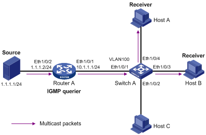
Configuration procedure
1) Configure the IP address of each interface
Configure an IP address and subnet mask for each interface as per Figure 6-3. The detailed configuration steps are omitted.
2) Configure Router A
# Enable IP multicast routing, enable PIM-DM on each interface, and enable IGMP on Ethernet 1/0/1.
<RouterA> system-view
[RouterA] multicast routing-enable
[RouterA] interface Ethernet 1/0/1
[RouterA-Ethernet1/0/1] igmp enable
[RouterA-Ethernet1/0/1] pim dm
[RouterA-Ethernet1/0/1] quit
[RouterA] interface Ethernet 1/0/2
[RouterA-Ethernet1/0/2] pim dm
[RouterA-Ethernet1/0/2] quit
3) Configure Switch A
# Enable IGMP Snooping globally.
<SwitchA> system-view
[SwitchA] igmp-snooping enable
Enable IGMP-Snooping ok.
# Create VLAN 100, assign Ethernet 1/0/1 through Ethernet 1/0/4 to this VLAN, and enable IGMP Snooping in the VLAN.
[SwitchA] vlan 100
[SwitchA-vlan100] port Ethernet 1/0/1 to Ethernet 1/0/4
[SwitchA-vlan100] igmp-snooping enable
[SwitchA-vlan100] quit
4) Verify the configuration
# View the detailed information of the multicast group in VLAN 100 on Switch A.
<SwitchA> display igmp-snooping group vlan100
Total 1 IP Group(s).
Total 1 MAC Group(s).
Vlan(id):100.
Total 1 IP Group(s).
Total 1 MAC Group(s).
Static Router port(s):
Dynamic Router port(s):
Ethernet1/0/1
IP group(s):the following ip group(s) match to one mac group.
IP group address: 224.1.1.1
Static host port(s):
Dynamic host port(s):
Ethernet1/0/3 Ethernet1/0/4
MAC group(s):
MAC group address: 0100-5e01-0101
Host port(s): Ethernet1/0/3 Ethernet1/0/4
As shown above, the multicast group 224.1.1.1 has been registered on Switch A, with the dynamic router port Ethernet 1/0/1 and dynamic member ports Ethernet 1/0/3 and Ethernet 1/0/4. This means that Host A and Host B have joined the multicast group 224.1.1.1.
Configuring Multicast VLAN
Network requirements
As shown in Figure 6-4, Workstation is a multicast source. Switch A forwards multicast data from the multicast source. A Layer 2 switch, Switch B forwards the multicast data to the end users Host A and Host B.
Table 6-2 describes the network devices involved in this example and the configurations you should make on them.
Table 6-2 Network devices and their configurations
|
Device |
Device description |
Networking description |
|
Switch A |
Layer 3 switch |
The interface IP address of VLAN 20 is 168.10.1.1. Ethernet 1/0/1 is connected to the workstation and belongs to VLAN 20. The interface IP address of VLAN 10 is 168.10.2.1. Ethernet 1/0/10 belongs to VLAN 10. Ethernet 1/0/10 is connected to Switch B. |
|
Switch B |
Layer 2 switch |
l VLAN 2 contains Ethernet 1/0/1 and VLAN 3 contains Ethernet 1/0/2. l The default VLANs of Ethernet 1/0/1 and Ethernet 1/0/2 are VLAN 2 and VLAN 3 respectively. l VLAN 10 contains Ethernet 1/0/10, Ethernet 1/0/1, and Ethernet 1/0/2. Ethernet 1/0/10 is connected to Switch A. l VLAN 10 is a multicast VLAN. l Ethernet 1/0/1 sends untagged packets for VLAN 2 and VLAN 10. l Ethernet 1/0/2 sends untagged packets for VLAN 3 and VLAN 10. |
|
Host A |
User 1 |
Host A is connected to Ethernet 1/0/1 on Switch B. |
|
Host B |
User 2 |
Host B is connected to Ethernet 1/0/2 on Switch B. |
In this configuration example, you need to configure the ports that connect Switch A and Switch B to each other as hybrid ports. The following text describes the configuration details. You can also configure these ports as trunk ports. The configuration procedure is omitted here. For details, see Configuring Multicast VLAN.
Configure a multicast VLAN, so that users in VLAN 2 and VLAN 3 can receive multicast streams through the multicast VLAN.
Network diagram
Figure 6-4 Network diagram for multicast VLAN configuration
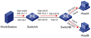
Configuration procedure
The following configuration is based on the prerequisite that the devices are properly connected and all the required IP addresses are already configured.
1) Configure Switch A:
# Set the interface IP address of VLAN 20 to 168.10.1.1 and enable PIM DM on the VLAN interface.
<SwitchA> system-view
[SwitchA] multicast routing-enable
[SwitchA] vlan 20
[SwitchA–vlan20]port Ethernet 1/0/1
[SwitchA-vlan20] quit
[SwitchA] interface Vlan-interface 20
[SwitchA-Vlan-interface20] ip address 168.10.1.1 255.255.255.0
[SwitchA-Vlan-interface20] pim dm
[SwitchA-Vlan-interface20] quit
# Configure VLAN 10.
[SwitchA] vlan 10
[SwitchA-vlan10] quit
# Define Ethernet 1/0/10 as a hybrid port, add the port to VLAN 10, and configure the port to forward tagged packets for VLAN 10.
[SwitchA] interface Ethernet 1/0/10
[SwitchA-Ethernet1/0/10] port link-type hybrid
[SwitchA-Ethernet1/0/10] port hybrid vlan 10 tagged
[SwitchA-Ethernet1/0/10] quit
# Configure the interface IP address of VLAN 10 as 168.10.2.1, and enable PIM-DM and IGMP.
[SwitchA] interface Vlan-interface 10
[SwitchA-Vlan-interface10] ip address 168.10.2.1 255.255.255.0
[SwitchA-Vlan-interface10] igmp enable
[SwitchA-Vlan-interface10] pim dm
2) Configure Switch B:
# Enable the IGMP Snooping feature on Switch B.
<SwitchB> system-view
[SwitchB] igmp-snooping enable
# Create VLAN 2, VLAN 3 and VLAN 10, configure VLAN 10 as the multicast VLAN, and then enable IGMP Snooping on it.
[SwitchB] vlan 2 to 3
Please wait.... Done.
[SwitchB] vlan 10
[SwitchB-vlan10] service-type multicast
[SwitchB-vlan10] igmp-snooping enable
[SwitchB-vlan10] quit
# Define Ethernet 1/0/10 as a hybrid port, add the port to VLAN 2, VLAN 3, and VLAN 10, and configure the port to forward tagged packets for VLAN 2, VLAN 3, and VLAN 10.
[SwitchB] interface Ethernet 1/0/10
[SwitchB-Ethernet1/0/10] port link-type hybrid
[SwitchB-Ethernet1/0/10] port hybrid vlan 2 3 10 tagged
[SwitchB-Ethernet1/0/10] quit
# Define Ethernet 1/0/1 as a hybrid port, add the port to VLAN 2 and VLAN 10, configure the port to forward untagged packets for VLAN 2 and VLAN 10, and set VLAN 2 as the default VLAN of the port.
[SwitchB] interface Ethernet 1/0/1
[SwitchB-Ethernet1/0/1] port link-type hybrid
[SwitchB-Ethernet1/0/1] port hybrid vlan 2 10 untagged
[SwitchB-Ethernet1/0/1] port hybrid pvid vlan 2
[SwitchB-Ethernet1/0/1] quit
# Define Ethernet 1/0/2 as a hybrid port, add the port to VLAN 3 and VLAN 10, configure the port to forward untagged packets for VLAN 3 and VLAN 10, and set VLAN 3 as the default VLAN of the port.
[SwitchB] interface Ethernet 1/0/2
[SwitchB-Ethernet1/0/2] port link-type hybrid
[SwitchB-Ethernet1/0/2] port hybrid vlan 3 10 untagged
[SwitchB-Ethernet1/0/2] port hybrid pvid vlan 3
[SwitchB-Ethernet1/0/2] quit
Troubleshooting IGMP Snooping
Symptom: Multicast function does not work on the switch.
Solution:
Possible reasons are:
1) IGMP Snooping is not enabled.
l Use the display current-configuration command to check the status of IGMP Snooping.
l If IGMP Snooping is disabled, check whether it is disabled globally or in the specific VLAN. If it is disabled globally, use the igmp-snooping enable command in both system view and VLAN view to enable it both globally and on the corresponding VLAN at the same time. If it is only disabled on the corresponding VLAN, use the igmp-snooping enable command in VLAN view only to enable it on the corresponding VLAN.
2) Multicast forwarding table set up by IGMP Snooping is wrong.
l Use the display igmp-snooping group command to check if the multicast groups are expected ones.
l If the multicast group set up by IGMP Snooping is not correct, contact your technical support personnel.