- Table of Contents
-
- H3C S3600 Operation Manual-Release 1602(V1.02)
- 00-1Cover
- 00-2Product Overview
- 01-CLI Operation
- 02-Login Operation
- 03-Configuration File Management Operation
- 04-VLAN Operation
- 05-IP Address and Performance Operation
- 06-Voice VLAN Operation
- 07-GVRP Operation
- 08-Port Basic Configuration Operation
- 09-Link Aggregation Operation
- 10-Port Isolation Operation
- 11-Port Security-Port Binding Operation
- 12-DLDP Operation
- 13-MAC Address Table Management Operation
- 14-Auto Detect Operation
- 15-MSTP Operation
- 16-Routing Protocol Operation
- 17-Multicast Operation
- 18-802.1x and System Guard Operation
- 19-AAA Operation
- 20-Web Authentication Operation
- 21-MAC Address Authentication Operation
- 22-VRRP Operation
- 23-ARP Operation
- 24-DHCP Operation
- 25-ACL Operation
- 26-QoS-QoS Profile Operation
- 27-Web Cache Redirection Operation
- 28-Mirroring Operation
- 29-IRF Fabric Operation
- 30-Cluster Operation
- 31-PoE-PoE Profile Operation
- 32-UDP Helper Operation
- 33-SNMP-RMON Operation
- 34-NTP Operation
- 35-SSH Operation
- 36-File System Management Operation
- 37-FTP-SFTP-TFTP Operation
- 38-Information Center Operation
- 39-System Maintenance and Debugging Operation
- 40-VLAN-VPN Operation
- 41-HWPing Operation
- 42-IPv6 Management Operation
- 43-DNS Operation
- 44-Smart Link-Monitor Link Operation
- 45-Access Management Operation
- 46-Appendix
- Related Documents
-
| Title | Size | Download |
|---|---|---|
| 16-Routing Protocol Operation | 828.17 KB |
Table of Contents
1 IP Routing Protocol Overview
Introduction to IP Route and Routing Table
Static Routing and Dynamic Routing
Classification of Dynamic Routing Protocols
Routing Protocols and Routing Priority
Displaying and Maintaining a Routing Table
Displaying and Maintaining Static Routes
Static Route Configuration Example
Troubleshooting a Static Route
Configuring Basic RIP Functions
RIP Network Adjustment and Optimization
Displaying and Maintaining RIP Configuration
Troubleshooting RIP Configuration
OSPF Area Partition and Route Summarization
OSPF Area Attribute Configuration
Configuring OSPF Area Attributes
OSPF Network Type Configuration
Configuring the Network Type of an OSPF Interface
Configuring an NBMA/P2MP Neighbor
Configuring the DR Priority on an OSPF Interface
Configuring OSPF Route Summarization
Configuring OSPF to Filter Received Routes
Configuring the OSPF Cost on an Interface
Configuring OSPF Route Priority
Configuring the Maximum Number of OSPF ECMP Routes
Configuring OSPF to Redistribute External Routes
OSPF Network Adjustment and Optimization
Configuring the LSA transmission delay
Configuring the SPF Calculation Interval
Disabling OSPF Packet Transmission on an Interface
Configuring OSPF Authentication
Configuring the MTU Field in DD Packets
Enabling OSPF Logging of Neighbor State Changes
Configuring OSPF Network Management
Displaying and Maintaining OSPF Configuration
Troubleshooting OSPF Configuration
Unable to Establish a Neighbor Relationship between Routers
Unable to Learn a Complete Network Topology
5 IP Route Policy Configuration
Introduction to IP Route Policy
IP Route Policy Configuration Task List
Defining if-match Clauses and apply Clauses
IP Route Policy Configuration Example
Configuring to Filter Received Routing Information
Controlling RIP Packet Cost to Implement Dynamic Route Backup
Troubleshooting IP Route Policy
6 Route Capacity Configuration
Route Capacity Configuration Overview
Route Capacity Limitation Configuration
Configuring the Lower Limit and the Safety Value of the Switch Memory
Enabling/Disabling Automatic Protocol Recovery
Displaying and Maintaining Route Capacity Limitation Configuration
Go to these sections for information you are interested in:
l Introduction to IP Route and Routing Table
l Displaying and Maintaining a Routing Table
![]()
l The term router in this chapter refers to a router in a generic sense or an Ethernet switch running a routing protocol.
l The S3600-SI series do not support OSPF.
l The feature of specifying the ABR of an NSSA area as the Type-7 LSAs translator is added. For the command used, refer to the part "Configure the current area to be an NSSA area" in OSPF Area Attribute Configuration.
l The feature of configuring an OSPF interface to unicast packets on a P2MP network is added. For the command used, refer to Configuring the Network Type of an OSPF Interface.
Introduction to IP Route and Routing Table
IP Route
Routers are used for route selection on the Internet. As a router receives a packet, it selects an appropriate route (through a network) according to the destination address of the packet and forwards the packet to the next router. The last router on the route is responsible for delivering the packet to the destination host.
Routing Table
Function
The key for a router to forward packets is the routing table. Each router maintains a routing table. Each entry in this table contains an IP address that represents a host/subnet and specifies which physical port on the router should be used to forward the packets destined for the host/subnet. And the router forwards those packets through this port to the next router or directly to the destination host if the host is on a network directly connected to the router.
Routes in a routing table can be divided into three categories by origin:
l Direct routes: Routes discovered by data link protocols, also known as interface routes.
l Static routes: Routes that are manually configured.
l Dynamic routes: Routes that are discovered dynamically by routing protocols.
Routing entry
Each routing entry in a routing table contains:
l Destination: It identifies the address of the destination host or network of an IP packet.
l Mask: Along with the destination address, it identifies the address of the network segment where the destination host or router resides. By performing a logical AND operation between destination address and network mask, you can get the address of the network segment where the destination host or router resides. For example, if the destination address is 129.102.8.10 and the mask is 255.255.0.0, the address of the network segment where the destination host or router resides is 129.102.0.0. A mask consists of some consecutive 1s, represented either in dotted decimal notation or by the number of the consecutive 1s in the mask.
l Interface: It indicates through which interface IP packets should be forwarded to the destination.
l Nexthop: It indicates the next router that IP packets will pass through to reach the destination.
l Preference: There may be multiple routes with different next hops to the same destination. These routes may be discovered by different routing protocols, or be manually configured static routes. The one with the highest preference (the smallest numerical value) will be selected as the current optimal route.
According to different destinations, routes fall into the following categories:
l Subnet route: The destination is a subnet.
l Host route: The destination is a host.
In addition, according to whether the network where the destination resides is directly connected to the router, routes fall into the following categories:
l Direct route: The router is directly connected to the network where the destination resides.
l Indirect route: The router is not directly connected to the network where the destination resides.
In order to avoid an oversized routing table, you can set a default route. All the packets for which the router fails to find a matching entry in the routing table will be forwarded through this default route.
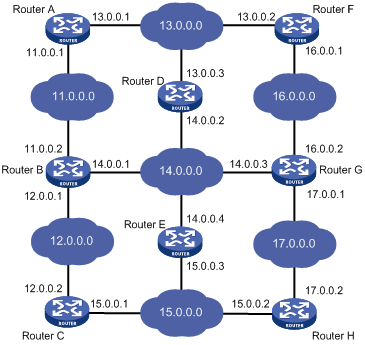
Figure 1-1 shows a relatively complicated internet environment, the number in each network cloud indicate the network address. Router G is connected to three networks, and so it has three IP addresses and three physical ports. Its routing table is shown in Figure 1-1.
|
Destination Network |
Nexthop |
Interface |
|
11.0.0.0 |
14.0.0.1 |
3 |
|
12.0.0.0 |
14.0.0.1 |
3 |
|
13.0.0.0 |
16.0.0.1 |
2 |
|
14.0.0.0 |
14.0.0.3 |
3 |
|
15.0.0.0 |
17.0.0.2 |
1 |
|
16.0.0.0 |
16.0.0.2 |
2 |
|
17.0.0.0 |
17.0.0.1 |
1 |
Routing Protocol Overview
Static Routing and Dynamic Routing
Static routing is easy to configure and requires less system resources. It works well in small, stable networks with simple topologies. It cannot adapt itself to any network topology change automatically so that you must perform routing configuration again whenever the network topology changes.
Dynamic routing is based on dynamic routing protocols, which can detect network topology changes and recalculate the routes accordingly. Therefore, dynamic routing is suitable for large networks. It is complicated to configure, and it not only imposes higher requirements on the system than static routing, but also occupies a certain amount of network resources.
Classification of Dynamic Routing Protocols
Dynamic routing protocols can be classified based on the following standards:
Operational scope
l Interior Gateway Protocols (IGPs): Work within an autonomous system, typically including RIP, OSPF, and IS-IS.
l Exterior Gateway Protocols (EGPs): Work between autonomous systems. The most popular one is BGP.
![]()
An autonomous system refers to a group of routers that share the same route policy and work under the same administration.
Routing algorithm
l Distance-vector protocols: RIP and BGP. BGP is also considered a path-vector protocol.
l Link-state protocols: OSPF and IS-IS.
The main differences between the above two types of routing algorithms lie in the way routes are discovered and calculated.
Type of the destination address
l Unicast routing protocols: RIP, OSPF, BGP, and IS-IS.
l Multicast routing protocols: PIM-SM and PIM-DM.
This chapter focuses on unicast routing protocols. For information on multicast routing protocols, refer to the part discussing Multicast.
Routing Protocols and Routing Priority
The following table lists some routing protocols and the default priorities for routes found by them:
Table 1-1 Routing protocols and priorities of their default route
|
Routing approach |
Priority |
|
DIRECT |
0 |
|
OSPF |
10 |
|
STATIC |
60 |
|
RIP |
100 |
|
OSPF ASE |
150 |
|
OSPF NSSA |
150 |
|
UNKNOWN |
255 |
![]()
l The smaller the priority value, the higher the priority.
l The priority for a direct route is always 0, which you cannot change. Any other type of routes can have their priorities manually configured.
l Each static route can be configured with a different priority.
Load Sharing and Route Backup
Load sharing
A given routing protocol may find several routes with the same metric to the same destination, and if this protocol has the highest priority among all the active protocols, these routes will be considered valid and are used to forward packets, thus achieving load sharing.
Route backup
You can configure multiple routes to the same destination, expecting the one with the highest priority to be the primary route and all the rest backup routes.
Route backup can help improve network reliability. Automatic switching can happen between the primary route and a backup route.
Under normal circumstances, packets are forwarded through the primary route. When the primary route goes down, the route with the highest priority among the backup routes is selected to forward packets. When the primary route recovers, the route selection process is performed again and the primary route is selected again to forward packets.
Routing Information Sharing
As different routing protocols use different algorithms to calculate routes, they may discover different routes. In a large network with multiple routing protocols, it is required for routing protocols to share their routing information. Each routing protocol shares routing information discovered by other routing protocols through a route redistribution mechanism.
Displaying and Maintaining a Routing Table
|
To do… |
Use the command… |
Remarks |
|
Display brief information about a routing table |
display ip routing-table [ | { begin | exclude | include } regular-expression ] |
Available in any view |
|
Display detailed information about a routing table |
display ip routing-table verbose |
|
|
Display information about routes permitted by a basic ACL |
display ip routing-table acl acl-number [ verbose ] |
|
|
Display information about routes permitted by a prefix list |
display ip routing-table ip-prefix ip-prefix-name [ verbose ] |
|
|
Display routes to a specified destination |
display ip routing-table ip-address [ mask | mask-length ] [ longer-match ] [ verbose ] |
|
|
Display routes to specified destinations |
display ip routing-table ip-address1 { mask1 | mask-length1 } ip-address2 { mask2 | mask-length2 } [ verbose ] |
|
|
Display routes discovered by a routing protocol |
display ip routing-table protocol protocol [ inactive | verbose ] |
|
|
Display the tree-structured routing table information |
display ip routing-table radix |
|
|
Display statistics about a routing table |
display ip routing-table statistics |
|
|
Clear statistics about a routing table |
reset ip routing-table statistics protocol { all | protocol } |
Available in user view |
When configuring a static route, go to these sections for information you are interested in:
l Introduction to Static Route
l Displaying and Maintaining Static Routes
l Static Route Configuration Example
l Troubleshooting a Static Route
![]()
The term router in this chapter refers to a router in a generic sense or an Ethernet switch running a routing protocol.
Introduction to Static Route
Static Route
Static routes are special routes. They are manually configured by the administrator. In a relatively simple network, you only need to configure static routes to make routers work normally. Proper configuration and usage of static routes can improve network performance and ensure sufficient bandwidth for important applications.
When the network topology changes, static routes may become unreachable because they cannot adapt themselves to the change automatically, thus resulting in network interruption. In this case, the network administrator needs to modify the configuration of static routes manually.
Static routes are divided into three types:
l Reachable route: normal route. If a static route to a destination is of this type, the IP packets destined for this destination will be forwarded to the next hop. It is the most common type of static routes.
l Unreachable route: route with the reject attribute. If a static route to a destination has the reject attribute, all the IP packets destined for this destination will be discarded, and the source hosts will be informed of the unreachability of the destination.
l Blackhole route: route with blackhole attribute. If a static route destined for a destination has the blackhole attribute, the outgoing interface of this route is the Null 0 interface regardless of the next hop address, and all the IP packets addressed to this destination will be dropped without notifying the source hosts.
The attributes reject and blackhole are usually used to limit the range of the destinations this router can reach, and help troubleshoot the network.
Default Route
To avoid too large a routing table, you can configure a default route.
When the destination address of a packet fails to match any entry in the routing table,
l If there is default route in the routing table, the default route will be selected to forward the packet.
l If there is no default route, the packet will be discarded and an ICMP Destination Unreachable or Network Unreachable packet will be returned to the source.
A default route can be manually configured or generated by some dynamic routing protocols, such as OSPF and RIP.
Static Route Configuration
Configuration Prerequisites
Before configuring a static route, perform the following tasks:
l Configuring the physical parameters of related interfaces
l Configuring IP addresses for related interfaces
Configuring a Static Route
Follow these steps to configure a static route:
|
To do... |
Use the command... |
Remarks |
|
Enter system view |
system-view |
— |
|
Configure a static route |
ip route-static ip-address { mask | mask-length } { interface-type interface-number | next-hop } [ preference preference-value ] [ reject | blackhole ] [ detect-group group number ] [ description text ] |
Required By default, the system can obtain the route to the subnet directly connected to the router. |
![]()
l Use the ip route-static command to configure a default route by setting the destination IP address and the mask to 0.0.0.0.
l Avoid configuring the next hop address of a static route to the address of an interface on the local switch.
l Different preferences can be configured to implement flexible route management policies.
l For automatic detection information, refer to the part discussing Auto Detect.
Displaying and Maintaining Static Routes
|
To do... |
Use the command... |
Remarks |
|
Display the current configuration information |
display current-configuration |
Available in any view |
|
Display the brief information of a routing table |
display ip routing-table |
|
|
Display the detailed information of a routing table |
display ip routing-table verbose |
|
|
Display the information of static routes |
display ip routing-table protocol static [ inactive | verbose ] |
|
|
Delete all static routes |
delete static-routes all |
Available in system view |
Static Route Configuration Example
Network requirements
In this case, static routes can implement communication between any two nodes.
Network diagram
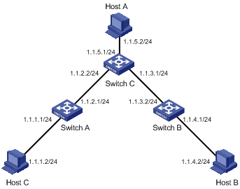
According to the network requirements, the network topology is designed as shown in Figure 2-1.
Figure 2-1 Network diagram for static route configuration
Configuration procedure
![]()
When only one interface of the device is interconnected with another network segment, you can implement network communication by configuring either a static route or default route.
1) Perform the following configurations on the switch.
# Approach 1: Configure static routes on Switch A.
<SwitchA> system-view
[SwitchA] ip route-static 1.1.3.0 255.255.255.0 1.1.2.2
[SwitchA] ip route-static 1.1.4.0 255.255.255.0 1.1.2.2
[SwitchA] ip route-static 1.1.5.0 255.255.255.0 1.1.2.2
# Approach 2: Configure a static route on Switch A.
<SwitchA> system-view
[SwitchA] ip route-static 0.0.0.0 0.0.0.0 1.1.2.2
# Approach 1: Configure static routes on Switch B.
<SwitchB> system-view
[SwitchB] ip route-static 1.1.2.0 255.255.255.0 1.1.3.1
[SwitchB] ip route-static 1.1.5.0 255.255.255.0 1.1.3.1
[SwitchB] ip route-static 1.1.1.0 255.255.255.0 1.1.3.1
# Approach 2: Configure a static route on Switch B.
<SwitchB> system-view
[SwitchB] ip route-static 0.0.0.0 0.0.0.0 1.1.3.1
# Configure static routes on Switch C.
<SwitchC> system-view
[SwitchC] ip route-static 1.1.1.0 255.255.255.0 1.1.2.1
[SwitchC] ip route-static 1.1.4.0 255.255.255.0 1.1.3.2
2) Perform the following configurations on the host.
# Set the default gateway address of Host A to 1.1.5.1. Detailed configuration procedure is omitted.
# Set the default gateway address of Host B to 1.1.4.1. Detailed configuration procedure is omitted.
# Set the default gateway address of Host C to 1.1.1.1. Detailed configuration procedure is omitted.
Now, all the hosts and switches in the figure can communicate with each other.
Troubleshooting a Static Route
Symptom: The switch is not configured with a dynamic routing protocol. Both the physical status and the link layer protocol status of an interface are UP, but IP packets cannot be forwarded on the interface.
Solution: Perform the following procedure.
1) Use the display ip routing-table protocol static command to view whether the corresponding static route is correctly configured.
2) Use the display ip routing-table command to view whether the static route is valid.
When configuring RIP, go to these sections for information you are interested in:
l Troubleshooting RIP Configuration
![]()
The term router in this chapter refers to a router in a generic sense or an Ethernet switch running a routing protocol.
RIP Overview
Routing information protocol (RIP) is a simple interior gateway protocol (IGP) suitable for small-sized networks. RIP is not recommended in complicated large networks.
Basic Concepts
RIP
RIP is a distance-vector (D-V) algorithm–based protocol. It uses port 520 to exchange routing information through UDP packets.
RIP uses hop count (also called routing cost) to measure the distance to a destination address. In RIP, the hop count from a router to its directly connected network is 0, and that to a network which can be reached through another router is 1, and so on. To restrict the time to converge, RIP prescribes that the cost is an integer ranging from 0 and 15. The hop count equal to or exceeding 16 is defined as infinite; that is, the destination network or host is unreachable. This limitation makes RIP not suitable for large networks.
To improve performance and avoid routing loop, RIP supports split horizon. Besides, RIP can import routes discovered by other routing protocols.
RIP routing database
Each RIP router has a routing table containing routing entries of all reachable destinations, and each routing entry contains:
l Destination address: IP address of a host or network.
l Next hop: IP address of an interface on the adjacent router that IP packets should pass through to reach the destination.
l Interface: Outbound interface on this router, through which IP packets should be forwarded to reach the destination.
l Metric: Cost from the local router to the destination.
l Route time: Time elapsed since the routing entry was last updated. The time is reset to 0 every time the routing entry is updated.
RIP timers
As defined in RFC 1058, RIP is controlled by three timers: Period update, Timeout, and Garbage-collection.
l Period update timer: The period update timer defines the interval between routing updates.
l Timeout timer: The timeout timer defines the route aging time. If no update for a route is received after the aging time elapses, the metric of the route is set to 16 in the routing table.
Routing loops prevention
RIP is a distance-vector (D-V) based routing protocol. Since a RIP router advertises its own routing table to neighbors, routing loops may occur.
RIP uses the following mechanisms to prevent routing loops.
l Counting to infinity. The metric value of 16 is defined as unreachable. When a routing loop occurs, the metric value of the route will increment to 16.
l Split horizon. A router does not send the routing information learned from a neighbor back to the neighbor to prevent routing loops and save the bandwidth.
RIP Startup and Operation
The whole process of RIP startup and operation is as follows:
l Once RIP is enabled on a router, the router broadcasts or multicasts a request packet to its neighbors. Upon receiving the packet, each neighbor running RIP answers a response packet containing its routing table information.
l When this router receives a response packet, it updates its local routing table and sends a triggered update packet to the neighbors. Upon receiving the triggered update packet, the neighbor sends the packet to all its neighbors. After a series of update triggering processes, each router can get and keep the updated routing information.
l By default, RIP sends its routing table to its neighbors every 30 seconds. Upon receiving the packets, the neighbors maintain their own routing tables and select optimal routes, and then advertise update information to their respective neighbors so as to make the updated routes known globally. Furthermore, RIP uses the aging mechanism to handle the timeout routes to ensure real-time and valid routes.
RIP Configuration Task List
Complete the following tasks to configure RIP:
|
Task |
Remarks |
|
|
Enabling RIP on the interfaces attached to a specified network segment |
Required |
|
|
Optional |
||
|
Optional |
||
|
Optional |
||
|
Optional |
||
|
Optional |
||
|
Optional |
||
|
Optional |
||
|
Optional |
||
|
Configuring RIP to redistribute routes from another protocol |
Optional |
|
|
Optional |
||
|
Optional |
||
|
Optional |
||
|
Optional |
||
|
Optional |
||
Basic RIP Configuration
Configuration Prerequisites
Before configuring basic RIP functions, perform the following tasks:
l Configuring the link layer protocol
Configuring Basic RIP Functions
Enabling RIP on the interfaces attached to a specified network segment
Follow these steps to enable RIP on the interfaces attached to a specified network segment:
|
To do... |
Use the command... |
Remarks |
|
Enter system view |
system-view |
— |
|
Enable RIP and enter RIP view |
rip |
Required |
|
Enable RIP on the specified interface |
network network-address |
Required Disabled by default |
![]()
l Related RIP commands configured in interface view can take effect only after RIP is enabled.
Setting the RIP operating status on an interface
Follow these steps to set the RIP operating status on an interface:
|
To do... |
Use the command... |
Remarks |
|
Enter system view |
system-view |
— |
|
Enter interface view |
interface interface-type interface-number |
— |
|
Enable the interface to receive RIP update packets |
rip input |
Optional Enabled by default |
|
Enable the interface to send RIP update packets |
rip output |
|
|
Enable the interface to receive and send RIP update packets |
rip work |
Specifying the RIP version on an interface
Follow these steps to specify the RIP version on an interface:
|
To do... |
Use the command... |
Remarks |
|
Enter system view |
system-view |
— |
|
Enter interface view |
interface interface-type interface-number |
— |
|
Specify the version of the RIP running on the interface |
rip version { 1 | 2 [ broadcast | multicast ] } |
Optional By default, the version of the RIP running on an interface is RIP-1. |
RIP Route Control
In actual implementation, it may be needed to control RIP routing information more accurately to accommodate complex network environments. By performing the configuration described in the following sections, you can:
l Control route selection by adjusting additional routing metrics on interfaces running RIP.
l Reduce the size of the routing table by setting route summarization and disabling the receiving of host routes.
l Filter incoming and outgoing routes.
l Redistribute external routes in an environment with multiple routing protocols.
Configuration Prerequisites
Before configuring RIP route control, perform the following tasks:
l Configuring network layer addresses of interfaces so that adjacent nodes are reachable to each other at the network layer
l Configuring basic RIP functions
Configuring RIP Route Control
Setting the additional routing metrics of an interface
Additional metric is the metric added to the original metrics of RIP routes on an interface. It does not directly change the metric value of a RIP route in the routing table of a router, but will be added to incoming or outgoing RIP routes on the interface.
Follow these steps to set additional routing metric:
|
To do... |
Use the command... |
Remarks |
|
Enter system view |
system-view |
— |
|
Enter interface view |
interface interface-type interface-number |
— |
|
Set the additional routing metric to be added for incoming RIP routes on this interface |
rip metricin value |
Optional 0 by default |
|
Set the additional routing metric to be added for outgoing RIP routes on this interface |
rip metricout value |
Optional 1 by default |
![]()
The rip metricout command takes effect only on the RIP routes learnt by the router and the RIP routes generated by the router itself, but the command is invalid for any route imported to RIP from other routing protocols.
Configuring RIP route summarization
Rip route summarization means that when the router advertises RIP updates, different subnet routes in the same natural network segment can be aggregated into one route with a natural mask for transmission to another network segment. This function is used to reduce the routing traffic on the network as well as the size of the routing table.
When it is necessary to advertise RIP route updates in a subnet, disable the route summarization for RIP-2.
Follow these steps to configure RIP route summarization:
|
To do... |
Use the command... |
Remarks |
|
Enter system view |
system-view |
— |
|
Enter RIP view |
rip |
— |
|
Enable RIP-2 automatic route summarization |
summary |
Required Enabled by default |
Disabling the router from receiving host routes
In some special cases, the router can receive a lot of host routes from the same segment, and these routes are of little help in route addressing but consume a lot of network resources. After a router is disabled from receiving host routes, it can refuse any incoming host route.
Follow these steps to disable the router from receiving host routes:
|
To do... |
Use the command... |
Remarks |
|
Enter system view |
system-view |
— |
|
Enter RIP view |
rip |
— |
|
Disable the router from receiving host routes |
undo host-route |
Required By default, the router receives host routes. |
Configuring RIP to filter incoming/outgoing routes
The route filtering function provided by a router enables you to configure inbound/outbound filter policy by specifying an ACL, address prefix list, or route policy to make RIP filter incoming/outgoing routes. Besides, you can configure RIP to receive only the RIP packets from a specific neighbor.
Follow these steps to configure RIP to filter incoming/outgoing routes:
|
To do... |
Use the command... |
Remarks |
|
Enter system view |
system-view |
— |
|
Enter RIP view |
rip |
— |
|
Configure RIP to filter incoming routes |
filter-policy { acl-number | ip-prefix ip-prefix-name [ gateway ip-prefix-name ] | route-policy route-policy-name } import |
Required By default, RIP does not filter any incoming route. The gateway keyword is used to filter the incoming routes advertised from a specified address. |
|
filter-policy gateway ip-prefix-name import |
||
|
Configure RIP to filter outgoing routes |
filter-policy { acl-number | ip-prefix ip-prefix-name } export [ protocol [ process-id ] ] |
Required By default, RIP does not filter any outgoing route. |
|
filter-policy route-policy route-policy-name export |
![]()
l The filter-policy import command filters the RIP routes received from neighbors, and the routes being filtered out will neither be added to the routing table nor be advertised to any neighbors.
l The filter-policy export command filters all the routes to be advertised, including the routes redistributed with the import-route command and routes learned from neighbors.
l You can also use the filter-policy export command to filter outgoing routes redistributed from a specified routing protocol.
Setting RIP preference
Follow these steps to set RIP preference:
|
To do... |
Use the command... |
Remarks |
|
Enter system view |
system-view |
— |
|
Enter RIP view |
rip |
— |
|
Set the RIP preference |
preference value |
Required 100 by default |
Enabling load sharing among RIP interfaces
Follow these steps to enable load sharing among RIP interfaces:
|
To do... |
Use the command... |
Remarks |
|
Enter system view |
system-view |
— |
|
Enter RIP view |
rip |
— |
|
Enable load sharing among RIP interfaces |
traffic-share-across-interface |
Required Disabled by default |
Configuring RIP to redistribute routes from another protocol
Follow these steps to configure RIP to import routes from another protocol:
|
To do... |
Use the command... |
Remarks |
|
Enter system view |
system-view |
— |
|
Enter RIP view |
rip |
— |
|
Configure a default cost for an incoming route |
default cost value |
Optional 1 by default |
|
Configure RIP to redistribute routes from another protocol |
import-route protocol [ process-id ] [ cost value | route-policy route-policy-name ]* |
Required By default, RIP does not redistribute any route from other protocols. |
RIP Network Adjustment and Optimization
In some special network environments, some RIP features need to be configured and RIP network performance needs to be adjusted and optimized. By performing the configuration mentioned in this section, the following can be implemented:
l Changing the convergence speed of RIP network by adjusting RIP timers;
l Avoiding routing loops by configuring split horizon;
l Packet validation in network environments with high security requirements, and
l Configuring RIP to unicast RIP messages on interfaces with special requirements.
Configuration Prerequisites
Before adjusting RIP, perform the following tasks:
l Configuring the network layer addresses of interfaces so that adjacent nodes are reachable to each other at the network layer
l Configuring basic RIP functions
Configuration Tasks
Configuring RIP timers
Follow these steps to configure RIP timers:
|
To do... |
Use the command... |
Remarks |
|
Enter system view |
system-view |
— |
|
Enter RIP view |
rip |
— |
|
Set the RIP timers |
timers { update update-timer | timeout timeout-timer } * |
Required By default, the Update timer is 30 seconds and the Timeout timer 180 seconds. |
![]()
When configuring the values of RIP timers, you should take network performance into consideration and perform consistent configuration on all routers running RIP to avoid unnecessary network traffic and network route oscillation.
Configuring split horizon
Follow these steps to configure split horizon:
|
To do... |
Use the command... |
Remarks |
|
Enter system view |
system-view |
— |
|
Enter interface view |
interface interface-type interface-number |
— |
|
Enable split horizon |
rip split-horizon |
Required Enabled by default |
Split horizon cannot be disabled on a point-to-point link.
Configuring RIP-1 packet zero field check
Follow these steps to configure RIP-1 packet zero field check:
|
To do... |
Use the command... |
Remarks |
|
Enter system view |
system-view |
— |
|
Enter RIP view |
rip |
— |
|
Enable the check of the must be zero field in RIP-1 packets |
checkzero |
Required Enabled by default |
![]()
Some fields in a RIP-1 packet must be 0, and they are known as must be zero field. For RIP-1, the must be zero field is checked for incoming packets, and those RIP-1 packets with this field being nonzero will not be processed.
Setting RIP-2 packet authentication mode
RIP-2 supports two authentication modes: simple authentication and message digest 5 (MD5) authentication.
Simple authentication cannot provide complete security, because the authentication keys sent along with packets that are not encrypted. Therefore, simple authentication cannot be applied where high security is required.
Follow these steps to set RIP-2 packet authentication mode:
|
To do... |
Use the command... |
Remarks |
|
Enter system view |
system-view |
— |
|
Enter interface view |
interface interface-type interface-number |
— |
|
Set RIP-2 packet authentication mode |
rip authentication-mode { simple password | md5 { rfc2082 key-string key-id | rfc2453 key-string } } |
Required If you specify to use MD5 authentication, you must specify one of the following MD5 authentication types: l rfc2453 (this type supports the packet format defined in RFC 2453) l rfc2082 (this type supports the packet format defined in RFC 2082) |
Configuring RIP to unicast RIP packets
Follow these steps to configure RIP to unicast RIP packets:
|
To do... |
Use the command... |
Remarks |
|
Enter system view |
system-view |
— |
|
Enter RIP view |
rip |
— |
|
Configure RIP to unicast RIP packets |
peer ip-address |
Required When RIP runs on the link that does not support broadcast or multicast, you must configure RIP to unicast RIP packets. |
Displaying and Maintaining RIP Configuration
|
To do... |
Use the command... |
Remarks |
|
Display the current RIP running status and configuration information |
display rip |
Available in any view |
|
Display RIP interface information |
display rip interface |
|
|
Display RIP routing information |
display rip routing |
|
|
Reset the system configuration related to RIP |
reset |
Available in RIP view |
RIP Configuration Example
Network requirements
A small-sized company requires that any two nodes in its small office network communicate with each other, and that the network devices automatically adapt themselves to any topology change so as to reduce the work of manual maintenance.
In this case, RIP can implement communication between any two nodes.
Network diagram
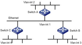
According to the network requirements, the network topology is designed as shown in Figure 3-1.
Figure 3-1 Network diagram for RIP configuration
|
Device |
Interface |
IP address |
Device |
Interface |
IP address |
|
Switch A |
Vlan-int1 |
110.11.2.1/24 |
Switch B |
Vlan-int1 |
110.11.2.2/24 |
|
|
Vlan-int2 |
155.10.1.1/24 |
|
Vlan-int3 |
196.38.165.1/24 |
|
Switch C |
Vlan-int1 |
110.11.2.3/24 |
|
|
|
|
|
Vlan-int4 |
117.102.0.1/16 |
|
|
|
Configuration procedure
![]()
Only the configuration related to RIP is listed below. Before the following configuration, make sure the Ethernet link layer works normally and the IP addresses of VLAN interfaces are configured correctly.
1) Configure Switch A:
# Configure RIP.
<SwitchA> system-view
[SwitchA] rip
[SwitchA-rip] network 110.11.2.0
[SwitchA-rip] network 155.10.1.0
2) Configure Switch B:
# Configure RIP.
<SwitchB> system-view
[SwitchB] rip
[SwitchB-rip] network 196.38.165.0
[SwitchB-rip] network 110.11.2.0
3) Configure Switch C:
# Configure RIP.
<SwitchC> system-view
[SwitchC] rip
[SwitchC-rip] network 117.102.0.0
[SwitchC-rip] network 110.11.2.0
Troubleshooting RIP Configuration
Failed to Receive RIP Updates
Symptom
The Ethernet switch cannot receive any RIP update when the physical connection between the switch and the peer routing device is normal.
Solution
Check that:
l RIP is enabled by using the network command on the corresponding interface.
l The interface is allowed to receive or send RIP packets.
l The interface receives RIP packets in the way the peer device sends them, for example, in the broadcast or multicast mode.
When configuring OSPF, go to these sections for information you are interested in:
l OSPF Configuration Task List
l Displaying and Maintaining OSPF Configuration
l Troubleshooting OSPF Configuration
![]()
l The term router in this chapter refers to a router in a generic sense or an Ethernet switch running a routing protocol.
l The S3600-SI series do not support OSPF.
OSPF Overview
Introduction to OSPF
Open Shortest Path First (OSPF) is a link state-based interior gateway protocol developed by IETF. At present, OSPF version 2 (RFC 2328) is used, which has the following features:
l High applicability: OSPF supports various networks in size, and even networks with up to several hundred routers.
l Fast convergence: OSPF can transmit update packets immediately after the network topology changes so that the change can be synchronized in the autonomous system (AS).
l Loop-free: Since OSPF calculates routes with the shortest path first algorithm according to the collected link states, it guarantees that no loop routes will be generated.
l Area partition: OSPF allows an autonomous system network to be divided into different areas for convenient management so that routing information transmitted between the areas is summarized further, thereby reducing network bandwidth consumption.
l Equivalent route: OSPF supports multiple equivalent routes to the same destination.
l Routing hierarchy: OSPF has a four-level routing hierarchy. It prioritizes the routes as intra-area, inter-area, external type-1, and external type-2 routes.
l Authentication: OSPF supports interface-based packet authentication to guarantee the security of route calculation.
l Multicast transmission: OSPF supports transmitting protocol packets in multicast mode.
OSPF Route Calculation
Taking no account of area partition, the routing calculation process of the OSPF protocol is as follows:
l Each OSPF-supported router maintains a link state database (LSDB), which describes the topology of the whole AS. According to the network topology around itself, each router generates a link state advertisement (LSA). Routers on the network exchange LSAs with each other by transmitting protocol packets. Thus, each router receives the LSAs of other routers and all these LSAs form the LSDB of the router.
l An LSA describes the network topology around a router, whereas an LSDB describes the network topology of the whole network. Routers can transform the LSDB to a weighted, directed graph, which reflects the real topology of the whole network. All routers get exactly the same weighted, directed graph.
l According to the weighted, directed graph, each router uses the shortest path first (SPF) algorithm to calculate the shortest path tree with itself as the root. The tree shows the routes to the nodes in the autonomous system. External routes are leaf nodes, which are marked with the routers from which they are advertised to record information outside the AS. The routing tables obtained by different routers are different.
Furthermore, to enable individual routers to broadcast their local status information (such as available interface information and reachable neighbor information) to the whole AS, routers in the AS should establish adjacencies among them. In this case, the route changes on any router will result in multiple transmissions, which are unnecessary and waste the precious bandwidth resources. To solve this problem, designated router (DR) and backup designated router (BDR) are defined in OSPF. For details about DR and BDR, see section "DR/BDR introduction".
OSPF supports interface-based packet authentication to guarantee the security of route calculation. In addition, it transmits and receives packets in multicast (224.0.0.5 and 224.0.0.6).
Basic OSPF Concepts
Autonomous System
A set of routers using the same routing protocol to exchange routing information constitute an Autonomous System (AS).
Router ID
To run OSPF, a router must have a router ID. A router ID can be configured manually. If no router ID is configured, the system will automatically select an IP address from the IP addresses of the interfaces as the router ID. A router ID is selected in the following way:
l If loopback interface addresses are configured, the system chooses the latest configured loopback interface IP address as the router ID.
l If no loopback interface is configured, the first configured IP address among the IP addresses of other interfaces will be the router ID.
OSPF Packets
OSPF uses five types of packets:
l Hello packet:
Hello packets are most commonly used OSPF packets, which are periodically sent by a router to its neighbors. A Hello packet contains the values of some timers, DR, BDR and known neighbors.
l DD packet:
When two routers synchronize their databases, they use database description (DD) packets to describe their own LSDBs, including the summary of each LSA. The summary refers to the header of an LSA which uniquely identifies the LSA. This reduces the size of traffic transmitted between the routers because the header of an LSA only occupies a small portion of the LSA. With the header, the peer router can judge whether it has the LSA or not.
l LSR packet:
After exchanging DD packets, the two routers know which LSAs of the peer router are lacked in the local LSDB, and send link state request (LSR) packets requesting for the lacked LSAs to the peer. These LSR packets contain the digest of the needed LSAs.
l LSU packet:
Link state update (LSU) packets are used to transmit the needed LSAs to the peer router. An LSU packet is a collection of multiple LSAs (complete LSAs, not LSA digest).
l LSAck packet
Link state acknowledgment (LSAck) packets are used to acknowledge received LSU packets. An LSAck contains the header(s) of LSA(s) to be acknowledged (One LSAck packet can acknowledge multiple LSAs).
LSA Types
1) Five basic LSA types
As described in the preceding sections, LSAs are the primary source for OSPF to calculate and maintain routes. RFC 2328 defines five types of LSAs:
l Router-LSA: Type-1 LSAs, generated by every router to describe the router's link states and costs, and advertised only in the originating area.
l Network-LSA: Type-2 LSAs, generated by the DRs on a broadcast or NBMA network to describe the link states of the current network segment, and are advertised only in the originating area.
l Summary-LSA: Type-3 and Type-4 LSAs, generated by ABRs and advertised in the areas associated with the LSAs. Each Summary-LSA describes a route to a destination in another area of the AS (also called inter-area route).Type-3 Summary-LSAs are for routes to networks (that is, their destinations are segments), while Type-4 Summary-LSAs are for routes to ASBRs.
l AS-external-LSA: Type-5 LSA, also called ASE LSA, generated by ASBRs to describe the routes to other ASs and advertised to the whole AS (excluding stub areas and NSSA areas). The default AS route can also be described by AS-external-LSAs.
2) Type-7 LSAs
In RFC 1587 (OSPF NSSA Option), Type-7 LSA, a new LSA type, is added.
As described in RFC 1587, Type-7 LSAs and Type-5 LSAs mainly differ in the following two ways:
l Type-7 LSAs are generated and advertised in an NSSA, where Type-5 LSAs will not be generated or advertised.
l Type-7 LSAs can only be advertised in an NSSA area. When Type-7 LSAs reach an ABR, the ABR can convert part of the routing information carried in the Type-7 LSAs into Type-5 LSAs and advertise the Type-5 LSAs. Type-7 LSAs are not directly advertised to other areas (including the backbone area).
Neighbor and Adjacency
In OSPF, neighbor and adjacency are two different concepts.
Neighbor: Two routers that have interfaces to a common network. Neighbor relationships are maintained by, and usually dynamically discovered by, OSPF's hello packets. When a router starts, it sends a hello packet through the OSPF interface, and the router that receives the hello packet checks parameters carried in the packet. If parameters of the two routers match, they become neighbors.
Adjacency: A relationship formed between selected neighboring routers for the purpose of exchanging routing information. Not every pair of neighboring routers become adjacent, which depends on network types. Only by synchronizing the LSDB via exchanging DD packets and LSAs can two routers become adjacent.
OSPF Area Partition and Route Summarization
Area partition
If all the routers on an ever-growing large network run OSPF, the large number of routers will result in an enormous LSDB, which will consume an enormous storage space, complicate the running of SPF algorithm, and increase CPU load.
Furthermore, as a network grows larger, it is more likely to have changes in the network topology. Hence, the network will often be “flapping”, and a great number of OSPF packets will be generated and transmitted in the network. This will lower the network bandwidth utilization. Even worse, any change of the topology will cause all the routers on the network to re-perform route calculation.
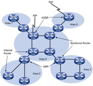
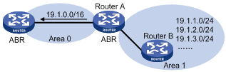
OSPF solves the above-mentioned problem by dividing an AS into multiple areas. Areas refer to groups into which routers are logically divided. Each group is identified by an Area ID, as shown in Figure 4-1.
Figure 4-1 OSPF area partition
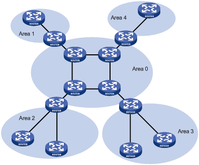
On the border of an area is a router, which belongs to different areas. After area partition, area border routers perform route summarization to reduce the number of LSAs advertised to other areas and minimize the effect of topology changes.
Classification of routers
The OSPF router falls into four types according to the position in the AS:
1) Internal router
All interfaces on an internal router belong to one OSPF area.
2) Area border router (ABR)
An area border router belongs to more than two areas, one of which must be the backbone area. It connects the backbone area to a non-backbone area. The connection between an area border router and the backbone area can be physical or logical.
3) Backbone router
At least one interface of a backbone router must be attached to the backbone area. Therefore, all ABRs and internal routers in area 0 are backbone routers.
4) Autonomous system border router (ASBR)
The router exchanging routing information with another AS is an ASBR, which may not reside on the boundary of the AS. It can be an internal router or area border router.
Figure 4-2 OSPF router types
5) Type-7 LSAs translator
A Type-7 LSAs translator takes effect on an ABR. The state of the Type-7 LSAs translator determines whether the ABR needs to translate Type-7 LSAs into Type-5 LSAs.
l When the Type-7 LSAs translator state is Enabled or Elected, the ABR translates Type-7 LSAs into Type-5 LSAs.
l When the Type-7 LSAs translator state is Disabled, the ABR does not translate Type-7 LSAs into Type-5 LSAs.
Backbone area and virtual link
1) Backbone area
With OSPF area partition, not all areas are equal. One of the areas is different from any other area. Its area ID is 0 and it is usually called the backbone area. Routing information between non-backbone areas must be forwarded by the backbone area. Therefore, OSPF requires:
l All non-backbone areas must maintain connectivity to the backbone area.
l The backbone area itself must maintain connectivity.
In practice, due to physical limitations, the requirements may not be satisfied. In this case, configuring OSPF virtual links is a solution.
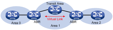
2) Virtual link
A virtual link is established between two area border routers through a non-backbone area and is configured on both ABRs to take effect. The area that provides the non-backbone area internal route for the virtual link is a “transit area”.
In the following figure, Area 2 has no direct physical link to the backbone area 0. Configuring a virtual link between ABRs can connect Area 2 to the backbone area.
Figure 4-3 Virtual link application 1
Another application of virtual links is to provide redundant links. If the backbone area cannot maintain internal connectivity due to a physical link failure, configuring a virtual link can guarantee logical connectivity in the backbone area, as shown below.
Figure 4-4 Virtual link application 2
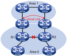
The virtual link between the two ABRs acts as a point-to-point connection. Therefore, you can configure interface parameters such as hello packet interval on the virtual link as they are configured on physical interfaces.
The two ABRs on the virtual link exchange OSPF packets with each other directly, the OSPF routers in between simply convey these OSPF packets as normal IP packets.
(Totally) Stub area
The ABR in a stub area does not distribute Type-5 LSAs into the area, so the routing table scale and amount of routing information in this area are reduced significantly.
You can also configure the stub area as a Totally Stub area, where the ABR advertises neither the routes of other areas nor the external routes.
Stub area configuration is optional, and not every area is qualified to be a stub area. In general, a stub area resides on the border of the AS.
The ABR in a stub area generates a default route into the area.
Note the following when configuring a (totally) stub area:
l The backbone area cannot be a (totally) stub area
l The stub command must be configured on routers in a (totally) stub area
l A (totally) stub area cannot have an ASBR because AS external routes cannot be distributed into the stub area.
l Virtual links cannot transit (totally) stub areas.
NSSA area
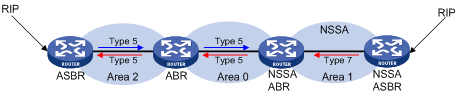
Similar to a stub area, an NSSA area imports no AS external LSA (Type-5 LSA) but can import Type-7 LSAs that are generated by the ASBR and distributed throughout the NSSA area. When reaching the NSSA ABR, Type-7 LSAs are translated into Type-5 LSAs by the ABR (the Type-7 LSAs translator state must be enabled/elected) before being advertised to other areas.
In the following figure, the OSPF AS contains three areas: Area 1, Area 2 and Area 0. The other two ASs employ the RIP protocol. Area 1 is an NSSA area, and the ASBR in it translates RIP routes into Type-7 LSAs and advertises them throughout Area 1. When these LSAs reach the NSSA ABR with the Type-7 LSAs translator state as Enabled or Elected, the ABR translates Type-7 LSAs to Type-5 LSAs for advertisement to Area 0 and Area 2.
On the left of the figure, RIP routes are translated into Type-5 LSAs by the ASBR of Area 2 and distributed into the OSPF AS. However, Area 1 is an NSSA area, so these Type-5 LSAs cannot travel to Area 1.
Similar to stub areas, virtual links cannot transit NSSA areas.
Figure 4-5 NSSA area
Route summarization
Route summarization: An ABR or ASBR summarizes routes with the same prefix with a single route and distribute it to other areas.
After an AS is divided into different areas that are interconnected through OSPF ABRs, The routing information between areas can be reduced through route summarization. This reduces the size of routing tables and improves the calculation speed of routers.
After an ABR in an area calculates the intra-area routes in the area, the ABR aggregates multiple OSPF routes into one LSA (based on the summarization configuration) and sends the LSA outside the area.
Figure 4-6 Route summarization
OSPF has two types of route summarization:
1) ABR route summarization
To distribute routing information to other areas, an ABR generates Type-3 LSAs on a per network segment basis for an attached non-backbone area. If contiguous network segments are available in the area, you can summarize them with a single network segment. The ABR in the area distributes only the summary LSA to reduce the scale of LSDBs on routers in other areas.
2) ASBR route summarization
If summarization for redistributed routes is configured on an ASBR, it will summarize redistributed Type-5 LSAs that fall into the specified address range. If in an NSSA area, it also summarizes Type-7 LSAs that fall into the specified address range.
If this feature is configured on an ABR, the ABR will summarize Type-5 LSAs translated from Type-7 LSAs.
Route types
OSPF prioritizes routes into four levels:
l Intra-area route
l Inter-area route
l type1 external route
l type2 external route
The intra-area and inter-area routes describe the network topology of the AS, while external routes describe routes to destinations outside the AS. OSPF classifies external routes into two types: type1 and type2.
A type1 external route is an IGP route, such as a RIP or static route, which has high credibility and whose cost is comparable with the cost of an OSPF internal route. The cost from a router to the destination of the type1 external route= the cost from the router to the corresponding ASBR+ the cost from the ASBR to the destination of the external route.
A type2 external route is an EGP route, which has low credibility, so OSPF considers the cost from the ASBR to the destination of the type2 external route is much bigger than the cost from the ASBR to an OSPF internal router. Therefore, the cost from the internal router to the destination of the type2 external route = the cost from the ASBR to the destination of the type2 external route. If two routes to the same destination have the same cost, then take the cost from the router to the ASBR into consideration.
OSPF Network Type
Four OSPF network types
OSPF divides networks into four types by link layer protocols:
l Broadcast: If Ethernet or FDDI is adopted, OSPF defaults the network type to broadcast. In a broadcast network, protocol packets are sent in multicast (224.0.0.5 and 224.0.0.6) by default.
l Non-broadcast multi-access (NBMA): If Frame Relay, ATM, or X.25 is adopted, OSPF defaults the network type to NBMA. In an NBMA network, protocol packets are sent in unicast.
l Point-to-multipoint (P2MP): OSPF will not default the network type of any link layer protocol to P2MP. A P2MP network must be compulsorily changed from another network type. The common practice is to change an NBMA network into a P2MP network. In a P2MP network, protocol packets are sent to the multicast address (224.0.0.5) by default, but protocol packets can be sent in the unicast address as needed.
l Point-to-point (P2P): If PPP or HDLC is adopted, OSPF defaults the network type to P2P. In a P2P network, protocol packets are sent in multicast (224.0.0.5).
Principles for configuring an NBMA network
An NBMA network is a non-broadcast and multi-accessible network. ATM and frame relay networks are typical NBMA networks.
Some special configurations need to be done on an NBMA network. In an NBMA network, an OSPF router cannot discover an adjacent router by broadcasting Hello packets. Therefore, you must manually specify an IP address for the adjacent router and whether the adjacent router has the right to vote for a DR.
An NBMA network must be fully connected. That is, any two routers in the network must be directly reachable to each other through a virtual circuit. If two routers in the network are not directly reachable to each other, you must configure the corresponding interface type to P2MP. If a router in the network has only one neighbor, you can change the corresponding interface type to P2P.
The differences between NBMA and P2MP are as follows:
l An NBMA network is fully connected, non-broadcast, and multi-accessible, whereas a P2MP network is not necessarily fully connected.
l DR and BDR are required to be elected on an NBMA network but not on a P2MP network.
l NBMA is a default network type. A P2MP network, however, must be compulsorily changed from another network type. The more common practice is to change an NBMA network into a P2MP network.
l Since NBMA interfaces send packets to unicast addresses, you need to configure neighbors manually. By default, P2MP sends protocol packets to multicast addresses.
DR/BDR
DR/BDR introduction
In a broadcast network or an NBMA network, routing information needs to be transmitted between any two routers. If there are n routers in the network, n × (n-1)/2 adjacencies need to be established. In this case, the route changes on any router will result in multiple transmissions, which waste bandwidth. To solve this problem, DR is defined in OSPF so that all routers send information to the DR only and the DR broadcasts the network link states in the network.
If the DR fails, a new DR must be elected and synchronized with the other routers on the network. The process takes quite a long time; in the process, route calculation is incorrect. To shorten the process, BDR is introduced in OSPF.
A BDR provides backup for a DR. DR and BDR are elected at the same time. Adjacencies are also established between the BDR and all the other routers on the segment, and routing information is also exchanged between them. Once the DR becomes invalid, the BDR becomes a DR. Since no re-election is needed and the adjacencies already exist, the switchover process is very short. Now, a new BDR should be elected. Although this election process will also take quite a long time, route calculation will not be affected.
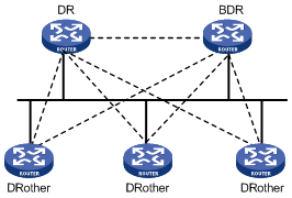
On an OSPF network, a router which is neither DR nor BDR is called DR Other. It establishes adjacencies with the DR and BDR, but not with other DR Others. This reduces not only the number of adjacencies among routers, but also the network traffic and occupied bandwidth resources on the broadcast or NBMA network.
In Figure 4-7, the solid lines represent physical Ethernet connections and the dotted lines represent adjacencies established. The figure shows that, with the DR/BDR mechanism adopted, seven adjacencies suffice among the five routers.
DR/BDR election
The DR and BDR in a network are elected by all routers rather than configured manually. The DR priority of an interface determines its qualification for DR/BDR election. Interfaces attached to the network and having priorities higher than ‘0” are election candidates.
The election votes are hello packets. Each router sends the DR elected by itself in a hello packet to all the other routers. If two routers on the network declare themselves as the DR, the router with the higher DR priority wins. If DR priorities are the same, the router with the higher Router ID wins. In addition, a router with the priority 0 cannot become the DR/BDR.
Note the following points:
l DR election is required for broadcast or NBMA interfaces but is not required for P2P or P2MP interfaces.
l DR is based on the router interfaces in a certain segment. A router may be a DR on an interface and a BDR or DR Other on another interface.
l The priority of a router affects the DR and BDR election. However, it has no effect on the election after the DR and BDR election ends. A new priority assigned to the router takes effect at the time of next DR and BDR election.
l If a new router is added after DR and BDR election, the router does not become the DR immediately even if it has the highest DR priority.
l The DR on a network segment is unnecessarily the router with the highest priority. Likewise, the BDR is unnecessarily the router with the second highest priority.
OSPF Features
The switches support the following OSPF features:
l Stub area: Stub area is defined to reduce the cost for the routers in the area to receive ASE routes.
l NSSA: NSSA is defined to remove the limit on the topology in a Stub area.
l OSPF multi-process: Multiple OSPF processes can be run on a router.
l Sharing discovered routing information with other dynamic routing protocols: At present, OSPF supports importing the routes of other dynamic routing protocols (such as RIP), and static routes as OSPF external routes into the AS to which the router belongs. In addition, OSPF supports advertising the routing information it discovered to other routing protocols.
l Packet authentication: OSPF supports the authentication of the packets between neighboring routers in the same area by using one of the two methods: plain text authentication and MD5 authentication.
l Flexible configuration of router interface parameters: For a router interface, you can configure the following OSPF parameters: output cost, Hello interval, retransmission interval, interface transmission delay, route priority, dead time for a neighboring router, and packet authentication mode and authentication key.
l Virtual link: Virtual links can be configured.
OSPF Configuration Task List
Complete the following tasks to configure OSPF:
|
Task |
Remarks |
|
|
Required |
||
|
Optional |
||
|
Optional |
||
|
Optional |
||
|
Optional |
||
|
Optional |
||
|
Optional |
||
|
Optional |
||
|
Optional |
||
|
Optional |
||
|
Optional |
||
|
Optional |
||
|
Optional |
||
|
Optional |
||
|
Optional |
||
|
Optional |
||
|
Optional |
||
|
Optional |
||
|
Optional |
||
Basic OSPF Configuration
Configuration Prerequisites
Before configuring OSPF, perform the following tasks:
l Configuring the link layer protocol
l Configuring the network layer addresses of interfaces so that the adjacent nodes are reachable to each other at the network layer
Basic OSPF Configuration
Basic OSPF configuration includes:
l Configuring router ID
To ensure stable OSPF operation, you should determine the division of router IDs and manually configure them when implementing network planning. When you configure router IDs manually, make sure each router ID is uniquely used by one router in the AS. A common practice is to set the IP address of an interface on the router to the router ID.
l Enabling OSPF
The switches support multiple OSPF processes. To enable multiple OSPF processes on a router, you need to specify different process IDs. OSPF process ID is only locally significant; it does not affect the packet exchange between an OSPF process and other routers. Therefore, packets can be exchanged between routers with different OSPF processes IDs.
l Configuring an area and the network segments in the area. You need to plan areas in an AS before performing the corresponding configurations on each router.
When configuring the routers in the same area, please note that most configurations should be uniformly made based on the area. Wrong configuration may disable information transmission between neighboring routers and even lead to congestion or self-loop of routing information.
Follow these steps to perform basic OSPF configurations:
|
To do... |
Use the command... |
Remarks |
|
Enter system view |
system-view |
— |
|
Configure the router ID |
router id router-id |
Optional If multiple OSPF processes run on a router, you are recommended to use the router-id keyword in the ospf command to specify different router IDs for different processes. |
|
Enable OSPF and enter OSPF view |
ospf [ process-id [ router-id router-id ] ] |
Required Enter OSPF view. |
|
Enter OSPF area view |
area area-id |
— |
|
Configure the network segments in the area |
network ip-address wildcard-mask |
Required By default, an interface does not belong to any area. |
![]()
l In router ID selection, the priorities of the router IDs configured with the ospf [ process-id [ router-id router-id ] ] command, the router id command, and the priorities of the router IDs automatically selected are in a descending order.
l Router IDs can be re-selected. A re-selected router ID takes effect only after the OSPF process is restarted.
l The ospf [ process-id [ router-id router-id ] ] command is recommended for configuring router IDs manually.
l An OSPF process ID on a router must be unique.
l One segment can belong to only one area and you must specify each OSPF interface to belong to a particular area.
OSPF Area Attribute Configuration
Area partition in OSPF reduces the number of LSAs in the network and enhances OSPF scalability. To further reduce routing table size and the number of LSAs in some non-backbone areas on the edge of the AS, you can configure these areas as stub areas.
A stub area cannot redistribute any external route. For this reason the concept of NSSA is introduced. Type-7 LSAs can be advertised in an NSSA. Type-7 LSAs are generated by ASBRs in the NSSA, and will be transformed into Type-5 LSAs (AS-external LSAs) when reaching ABRs in the NSSA area, which will then be advertised to other areas.
After area partition, the OSPF route updates between non-backbone areas are exchanged by way of the backbone area. Therefore, OSPF requires that all the non-backbone areas should keep connectivity with the backbone area and the backbone area must keep connectivity in itself.
Configuration Prerequisites
Before configuring OSPF area attributes, perform the following tasks:
l Configuring the network layer addresses of interfaces so that the adjacent nodes are reachable to each other at the network layer
l Performing basic OSPF configuration
Configuring OSPF Area Attributes
Follow these steps to configure OSPF area attributes:
|
To do... |
Use the command... |
Remarks |
|
Enter system view |
system-view |
— |
|
Enter OSPF view |
ospf [ process-id [ router-id router-id ] ] |
— |
|
Enter OSPF area view |
area area-id |
— |
|
Configure the current area to be a stub area |
stub [ no-summary ] |
Optional By default, no area is configured as a stub area. |
|
Configure the current area to be an NSSA area |
nssa [ default-route-advertise | no-import-route | no-summary | translate-always ] * |
Optional By default, no area is configured as an NSSA area. |
|
Configure the cost of the default route transmitted by OSPF to a stub or NSSA area |
default-cost cost |
Optional This can be configured on an ABR only. By default, the cost of the default route to a stub or NSSA area is 1. |
|
Create and configure a virtual link |
vlink-peer router-id [ hello seconds | retransmit seconds | trans-delay seconds | dead seconds | simple password | md5 keyid key ] * |
Optional For a virtual link to take effect, you need to use this command at both ends of the virtual link and ensure consistent configurations of the hello, dead, and other parameters at both ends. |
![]()
l You must use the stub command on all the routers connected to a stub area to configure the area with the stub attribute.
OSPF Network Type Configuration
OSPF divides networks into four types by link layer protocol. See section "OSPF Network Type". An NBMA network must be fully connected. That is, any two routers in the network must be directly reachable to each other through a virtual circuit. However, in many cases, this cannot be implemented and you need to use a command to change the network type forcibly.
Configure the network type of an interface as P2MP if not all the routers are directly accessible on an NBMA network. You can also configure the network type of an interface to P2P if the router has only one peer on the NBMA network.
Configuration Prerequisites
Before configuring the network type of an OSPF interface, perform the following tasks:
l Configuring the network layer address of the interface so that the adjacent node is reachable at network layer
l Performing basic OSPF configuration
Configuring the Network Type of an OSPF Interface
Follow these steps to configure the network type of an OSPF interface:
|
To do... |
Use the command... |
Remarks |
|
Enter system view |
system-view |
— |
|
Enter interface view |
interface interface-type interface-number |
— |
|
Configure the network type of the OSPF interface |
ospf network-type { broadcast | nbma | p2mp [ unicast ] | p2p } |
Required By default, the network type of an interface depends on the physical interface. |
![]()
l After an interface has been configured with a new network type, the original network type of the interface is removed automatically.
l An adjacency can be established between two interfaces configured as broadcast, NBMA, or P2MP only if the interfaces are on the same network segment.
l If the network type of an interface is NBMA or is changed to NBMA, you must use the peer command to specify the peer.
l If the network type of an interface is P2MP and the unicast keyword is specified, an interface sends packets in the unicast mode. In this case, you must use the peer command to specify the peer.
Configuring an NBMA/P2MP Neighbor
When the network type of an interface on the router is one of the following types, you need to specify the IP address of the neighbor router:
l NBMA
l P2MP ( required only when the interface sends packets in the unicast mode)
Since the neighbor routers cannot be discovered by broadcasting Hello packets, you must manually specify the IP address of the neighbor router. For an NBMA network, you can determine whether the neighbor has the DR election right.
Follow these steps to configure NBMA/P2MP neighbor:
|
To do... |
Use the command... |
Remarks |
|
Enter system view |
system-view |
— |
|
Enter OSPF view |
ospf [ process-id [ router-id router-id ] ] |
Required |
|
Configure an NBMA/P2MP neighbor |
peer ip-address [ dr-priority dr-priority ] |
Required By default, the priority for the neighbor of an NBMA interface is 1. |
Configuring the DR Priority on an OSPF Interface
You can control the DR/BDR election on a broadcast or NBMA network by configuring the DR priorities of interfaces.
Follow these steps to configure the DR priority on an OSPF interface:
|
To do... |
Use the command... |
Remarks |
|
Enter system view |
system-view |
— |
|
Enter interface view |
interface interface-type interface-number |
— |
|
Configure the DR priority on the OSPF interface |
ospf dr-priority priority |
Optional 1 by default |
![]()
The DR priorities configured by the ospf dr-priority command and the peer command have different purposes:
l The priority set with the ospf dr-priority command is used for actual DR election.
OSPF Route Control
Configuration Prerequisites
Before configuring OSPF route control, perform the following tasks:
l Configuring the network layer addresses of interfaces so that the adjacent nodes are reachable to each other at the network layer
l Completing basic OSPF configuration
l Configuring matching rules for routing information
Configuring OSPF Route Summarization
The configuration of OSPF route summarization includes:
l Configuring ABR route summarization,
l Configuring ASBR route summarization for imported routes.
Follow these steps to configure ABR route summarization:
|
To do... |
Use the command... |
Remarks |
|
Enter system view |
system-view |
— |
|
Enter OSPF view |
ospf [ process-id [ router-id router-id ] ] |
— |
|
Enter area view |
area area-id |
— |
|
Enable ABR route summarization |
abr-summary ip-address mask [ advertise | not-advertise ] |
Required This command takes effect only when it is configured on an ABR. By default, this function is disabled on an ABR. |
Follow these steps to configure ASBR route summarization:
|
To do... |
Use the command... |
Remarks |
|
Enter system view |
system-view |
— |
|
Enter OSPF view |
ospf [ process-id [ router-id router-id ] ] |
— |
|
Enable ASBR route summarization |
asbr-summary ip-address mask [ not-advertise | tag value ] |
Required By default, summarization of imported routes is disabled. |
Configuring OSPF to Filter Received Routes
Follow these steps to configure OSPF to filter received routes:
|
To do... |
Use the command... |
Remarks |
|
Enter system view |
system-view |
— |
|
Enter OSPF view |
ospf [ process-id [ router-id router-id ] ] |
— |
|
Configure to filter the received routes |
filter-policy { acl-number | ip-prefix ip-prefix-name | gateway ip-prefix-name } import |
Required By default, OSPF does not filter received routing information. |
![]()
OSPF is a dynamic routing protocol based on link state, with routing information hidden in LSAs. Therefore, OSPF cannot filter any advertised or received LSA. In fact, the filter-policy import command filters the routes calculated by SPF algorithm (namely, routes in the OSPF routing table); only the routes passing the filter can be added to the routing table.
Configuring the OSPF Cost on an Interface
Follow these steps to configure the OSPF cost on an interface:
|
To do... |
Use the command... |
Remarks |
|
Enter system view |
system-view |
— |
|
Enter interface view |
interface interface-type interface-number |
— |
|
Configure the OSPF cost on the interface |
ospf cost value |
Required By default, a VLAN interface on the switch, a fixed value of 10 is used. |
Configuring OSPF Route Priority
Since multiple dynamic routing protocols may be running on one router, the problem of route sharing and selection between various routing protocols arises. The system sets a priority for each routing protocol (which you can change manually), and when more than one route to the same destination is discovered by different protocols, the system add the route discovered by the protocol with the highest priority to the routing table.
Follow these steps to configure OSPF route priority:
|
To do... |
Use the command... |
Remarks |
|
Enter system view |
system-view |
— |
|
Enter OSPF view |
ospf [ process-id [ router-id router-id ] ] |
— |
|
Configure OSPF route priority |
preference [ ase ] value |
Required By default, the OSPF route priority is 10 and the priority of OSPF ASE is 150. |
Configuring the Maximum Number of OSPF ECMP Routes
Follow these steps to configure the maximum number of OSPF ECMP routes:
|
To do... |
Use the command... |
Remarks |
|
Enter system view |
system-view |
— |
|
Enter OSPF view |
ospf [ process-id [ router-id router-id ] ] |
— |
|
Configure the maximum number of OSPF ECMP routes |
multi-path-number value |
Optional 3 by default |
Configuring OSPF to Redistribute External Routes
Follow these steps to configure OSPF to redistribute external routes:
|
To do... |
Use the command... |
Remarks |
|
Enter system view |
system-view |
— |
|
Enter OSPF view |
ospf [ process-id [ router-id router-id ] ] |
— |
|
Configure OSPF to redistribute routes from another protocol |
import-route protocol [ process-id ] [ cost value | type value | tag value | route-policy route-policy-name ] * |
Required By default, OSPF does not import the routing information of other protocols. |
|
Configure OSPF to filter outgoing routes |
filter-policy { acl-number | ip-prefix ip-prefix-name } export [ protocol ] |
Optional By default, OSPF does not filter advertised routes. |
|
Enable OSPF to import the default route |
default-route-advertise [ always | cost value | type type-value | route-policy route-policy-name ]* |
Optional By default, OSPF does not import the default route. |
|
Configure the default parameters for redistributed routes, including cost, interval, limit, tag, and type |
default { cost value | interval seconds | limit routes | tag tag | type type } * |
Optional These parameters respectively default to: l Cost: 1 l Interval: 1 (second) l Limit: 1000 l Tag: 1 l Type: 2 |
![]()
l The import-route command cannot import the default route. To import the default route, you must use the default-route-advertise command.
l The filtering of advertised routes by OSPF means that OSPF only converts the external routes meeting the filter criteria into Type-5 or Type-7 LSAs and advertises them.
l When enabling OSPF to import external routes, you can also configure the defaults of some additional parameters, such as cost, limit, tag, and type. A route tag can be used to identify protocol-related information.
OSPF Network Adjustment and Optimization
You can adjust and optimize an OSPF network in the following aspects:
l By changing the OSPF packet timers, you can adjust the convergence speed of the OSPF network and the network load brought by OSPF packets. On some low-speed links, you need to consider the delay experienced when the interfaces transmit LSAs.
l By Adjusting SPF calculation interval, you can mitigate resource consumption caused by frequent network changes.
l In a network with high security requirements, you can enable OSPF authentication to enhance OSPF network security.
Configuration Prerequisites
Before adjusting and optimizing an OSPF network, perform the following tasks:
l Configuring the network layer addresses of interfaces so that the adjacent nodes are reachable to each other at the network layer
l Configuring basic OSPF functions
Configuring OSPF Timers
The Hello intervals for OSPF neighbors must be consistent. The value of Hello interval is in inverse proportion to route convergence speed and network load.
The dead time on an interface must be at least four times of the Hello interval on the same interface.
After a router sends an LSA to a neighbor, it waits for an acknowledgement packet from the neighbor. If the router receives no acknowledgement packet from the neighbor within the retransmission interval, it retransmits the LSA to the neighbor.
Follow these steps to configure OSPF timers:
|
To do... |
Use the command... |
Remarks |
|
Enter system view |
system-view |
— |
|
Enter interface view |
interface interface-type interface-number |
— |
|
Configure the hello interval on the interface |
ospf timer hello seconds |
Optional By default, p2p and broadcast interfaces send Hello packets every 10 seconds; while p2mp and NBMA interfaces send Hello packets every 30 seconds. |
|
Configure the poll interval on the NBMA interface |
ospf timer poll seconds |
Optional 40 seconds by default |
|
Configure the dead time of the neighboring router on the interface |
ospf timer dead seconds |
Optional By default, the dead time for the OSPF neighboring router on a p2p or broadcast interface is 40 seconds and that for the OSPF neighboring router on a p2mp or NBMA interface is 120 seconds. |
|
Configure the interval for retransmitting an LSA on an interface |
ospf timer retransmit interval |
Optional 5 seconds by default |
![]()
l Default Hello and Dead timer values will be restored once the network type is changed.
l Do not set an LSA retransmission interval that is too short. Otherwise, unnecessary retransmission will occur. LSA retransmission interval must be greater than the round trip time of a packet between two routers.
Configuring the LSA transmission delay
Follow these steps to configure the LSA transmission delay:
|
To do... |
Use the command... |
Remarks |
|
Enter system view |
system-view |
— |
|
Enter interface view |
interface interface-type interface-number |
— |
|
Configure the LSA transmission delay |
ospf trans-delay seconds |
Required 1 second by default |
![]()
The transmission of OSPF packets on a link also takes time. Therefore, a transmission delay should be added to the aging time of LSAs before the LSAs are transmitted. For a low-speed link, pay close attention on this configuration.
Configuring the SPF Calculation Interval
Whenever the LSDB of OSPF is changed, the shortest paths need to be recalculated. When the network changes frequently, calculating the shortest paths immediately after LSDB changes will consume enormous resources and affect the operation efficiency of the router. By adjusting the minimum SPF calculation interval, you can lighten the negative affect caused by frequent network changes.
Follow these steps to configure the SPF calculation interval:
|
To do... |
Use the command... |
Remarks |
|
Enter system view |
system-view |
— |
|
Enter OSPF view |
ospf [ process-id [ router-id router-id ] ] |
— |
|
Configure the SPF calculation interval |
spf-schedule-interval interval |
Required 5 seconds by default |
Disabling OSPF Packet Transmission on an Interface
To prevent OSPF routing information from being acquired by the routers on a certain network, use the silent-interface command to disable OSPF packet transmission on the corresponding interface.
Follow these steps to disable OSPF packet transmission on an interface:
|
To do... |
Use the command... |
Remarks |
|
Enter system view |
system-view |
— |
|
Enter OSPF view |
ospf [ process-id [ router-id router-id ] ] |
— |
|
Disable OSPF packet transmission on a specified interface |
silent-interface silent-interface-type silent-interface-number |
Required By default, all the interfaces are allowed to transmit OSPF packets. |
![]()
l On the same interface, you can disable multiple OSPF processes from transmitting OSPF packets. The silent-interface command, however, only applies to the OSPF interface on which the specified process has been enabled, without affecting the interface for any other process.
l After an OSPF interface is set to be in silent status, the interface can still advertise its direct route. However, the Hello packets from the interface will be blocked, and no adjacencies can be established on the interface. This enhances OSPF networking adaptability, thus reducing the consumption of system resources.
Configuring OSPF Authentication
Follow these steps to configure OSPF authentication:
|
To do... |
Use the command... |
Remarks |
|
Enter system view |
system-view |
— |
|
Enter OSPF view |
ospf [ process-id [ router-id router-id ] ] |
— |
|
Enter OSPF area view |
area area-id |
— |
|
Configure the authentication mode of the OSPF area |
authentication-mode { simple | md5 } |
Required Not configured by default |
|
Return to OSPF view |
quit |
— |
|
Return to system view |
quit |
— |
|
Enter interface view |
interface interface-type interface-number |
— |
|
Configure the authentication mode of the OSPF interface |
ospf authentication-mode { simple password | md5 key-id key } |
Optional By default, OSPF packets are not authenticated on an interface. |
![]()
l OSPF supports packet authentication and receives only those packets that are successfully authenticated. If packet authentication fails, no adjacencies will be established.
l The authentication modes for all routers in an area must be consistent. The authentication passwords for all routers on a network segment must also be consistent.
Configuring the MTU Field in DD Packets
By default, an interface uses value 0 instead of its actual MTU value when transmitting DD packets. After the following configuration, the actual interface MTU is filled in the MTU field in DD packets.
Follow these steps to configure to fill the MTU field when an interface transmits DD packets:
|
To do... |
Use the command... |
Remarks |
|
Enter system view |
system-view |
— |
|
Enter interface view |
interface interface-type interface-number |
— |
|
Enable the interface to fill in the MTU field when transmitting DD packets |
ospf mtu-enable |
Required By default, the MTU value is 0 when an interface transmits DD packets. That is, the actual MTU value of the interface is not filled in. |
Enabling OSPF Logging of Neighbor State Changes
Follow these steps to enable OSPF logging of neighbor state changes:
|
To do... |
Use the command... |
Remarks |
|
Enter system view |
system-view |
— |
|
Enter OSPF view |
ospf [ process-id [ router-id router-id ] ] |
— |
|
Enable the OSPF logging of neighbor state changes |
log-peer-change |
Required Disabled by default |
Configuring OSPF Network Management
Follow these steps to configure OSPF network management (NM):
|
To do... |
Use the command... |
Remarks |
|
Enter system view |
system-view |
— |
|
Configure OSPF MIB binding |
ospf mib-binding process-id |
Optional By default, OSPF MIB is bound to the first enabled OSPF process. |
|
Enable OSPF Trap sending |
snmp-agent trap enable ospf [ process-id ] [ ifauthfail | ifcfgerror | ifrxbadpkt | ifstatechange | iftxretransmit | lsdbapproachoverflow | lsdboverflow | maxagelsa | nbrstatechange | originatelsa | vifauthfail | vifcfgerror | virifrxbadpkt | virifstatechange | viriftxretransmit | virnbrstatechange ]* |
Optional You can configure OSPF to send diversified SNMP TRAP messages and specify a certain OSPF process to send SNMP TRAP messages by process ID. |
Displaying and Maintaining OSPF Configuration
|
To do... |
Use the command... |
Remarks |
|
Display the router ID |
display router id |
Available in any view |
|
Display brief information about one or all OSPF processes |
display ospf [ process-id ] brief |
|
|
Display OSPF statistics |
display ospf [ process-id ] cumulative |
|
|
Display OSPF LSDB information |
display ospf process-id area-id lsdb [ brief | [ [ asbr | network | nssa | router | summary ] [ ip-address ] ] [ originate-router ip-address | self-originate ] ] display ospf [ process-id ] lsdb [ brief | [ [ asbr | ase | network | nssa | router | summary ] [ ip-address ] ] [ originate-router ip-address | self-originate ] ] |
|
|
Display OSPF peer information |
display ospf [ process-id ] peer [ brief | statistics ] |
|
|
Display OSPF next hop information |
display ospf [ process-id ] nexthop |
|
|
Display OSPF routing table |
display ospf [ process-id ] routing |
|
|
Display OSPF virtual links |
display ospf [ process-id ] vlink |
|
|
Display OSPF request list |
display ospf [ process-id ] request-queue |
|
|
Display OSPF retransmission list |
display ospf [ process-id ] retrans-queue |
|
|
Display the information about OSPF ABR and ASBR |
display ospf [ process-id ] abr-asbr |
|
|
Display OSPF interface information |
display ospf [ process-id ] interface interface-type interface-number |
|
|
Display OSPF errors |
display ospf [ process-id ] error |
|
|
Display OSPF ASBR summarization information |
display ospf [ process-id ] asbr-summary [ ip-address mask ] |
|
|
Reset OSPF process(es) |
reset ospf { all | process-id } |
Available in user view |
|
Clear the statistics of one or all OSPF processes |
reset ospf statistics { all | process-id } |
OSPF Configuration Examples
Configuring DR/BDR Election
Network requirements
Based on the customer requirements and networking environment, assign proper priorities to interfaces.
Network diagram
Figure 4-8 Network diagram for DR/BDR election
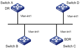
|
Device |
Interface |
IP address |
Router ID |
Interface priority |
|
Switch A |
Vlan-int1 |
196.1.1.1/24 |
1.1.1.1 |
100 |
|
Switch B |
Vlan-int1 |
196.1.1.2/24 |
2.2.2.2 |
0 |
|
Switch C |
Vlan-int1 |
196.1.1.3/24 |
3.3.3.3 |
2 |
|
Switch D |
Vlan-int1 |
196.1.1.4/24 |
4.4.4.4 |
1 |
Configuration procedure
# Configure Switch A.
<SwitchA> system-view
[SwitchA] interface Vlan-interface 1
[SwitchA-Vlan-interface1] ip address 196.1.1.1 255.255.255.0
[SwitchA-Vlan-interface1] ospf dr-priority 100
[SwitchA-Vlan-interface1] quit
[SwitchA] router id 1.1.1.1
[SwitchA] ospf
[SwitchA-ospf-1] area 0
[SwitchA-ospf-1-area-0.0.0.0] network 196.1.1.0 0.0.0.255
# Configure Switch B.
<SwitchB> system-view
[SwitchB] interface Vlan-interface 1
[SwitchB-Vlan-interface1] ip address 196.1.1.2 255.255.255.0
[SwitchB-Vlan-interface1] ospf dr-priority 0
[SwitchB-Vlan-interface1] quit
[SwitchB] router id 2.2.2.2
[SwitchB] ospf
[SwitchB-ospf-1] area 0
[SwitchB-ospf-1-area-0.0.0.0] network 196.1.1.0 0.0.0.255
# Configure Switch C.
<SwitchC> system-view
[SwitchC] interface Vlan-interface 1
[SwitchC-Vlan-interface1] ip address 196.1.1.3 255.255.255.0
[SwitchC-Vlan-interface1] ospf dr-priority 2
[SwitchC-Vlan-interface1] quit
[SwitchC] router id 3.3.3.3
[SwitchC] ospf
[SwitchC-ospf-1] area 0
[SwitchC-ospf-1-area-0.0.0.0] network 196.1.1.0 0.0.0.255
# Configure Switch D.
<SwitchD> system-view
[SwitchD] interface Vlan-interface 1
[SwitchD-Vlan-interface1] ip address 196.1.1.4 255.255.255.0
[SwitchD-Vlan-interface1] quit
[SwitchD] router id 4.4.4.4
[SwitchD] ospf
[SwitchD-ospf-1] area 0
[SwitchD-ospf-1-area-0.0.0.0] network 196.1.1.0 0.0.0.255
On Switch A, run the display ospf peer command to display its OSPF peers. Note that Switch A has three peers.
The state of each peer is full, which means that adjacency is established between Switch A and each peer. Switch A and Switch C must establish adjacencies with all the switches on the network so that they can serve as the DR and BDR respectively on the network. Switch A is DR, while Switch C is BDR on the network. All the other neighbors are DR others (This means that they are neither DRs nor BDRs).
# Change the priority of Switch B to 200.
<SwitchB> system-view
[SwitchB] interface Vlan-interface 1
[SwitchB-Vlan-interface1] ospf dr-priority 200
On Switch A, use the display ospf peer command to display its OSPF neighbors. Note that the priority of Switch B has been changed to 200, but it is still not a DR.
The current DR is changed only when it is offline. Shut down Switch A, and use the display ospf peer command on Switch D to display its neighbors. Note that the original BDR (Switch C) becomes the DR and Switch B becomes BDR now.
If all Ethernet Switches on the network are removed from and then added to the network again, Switch B will be elected as the DR (with a priority of 200), and Switch A will be the BDR (with a priority of 100). Shutting down and restarting all the switches will bring about a new round of DR/BDR election on the network.
Configuring OSPF Virtual Link
Network requirements
Devices in the network run OSPF to realize interconnection. The network is split into three areas: one backbone area and two non-backbone areas (Area 1 and Area 2). Area 2 has no direct connection to the backbone, and it has to reach the backbone through Area 1. The customer hopes that Area 2 can interconnect with other two areas.
Based on the customer requirements and networking environment, use a virtual link to connect Area 2 to the backbone area.
Network diagram
Figure 4-9 Network diagram for OSPF virtual link configuration
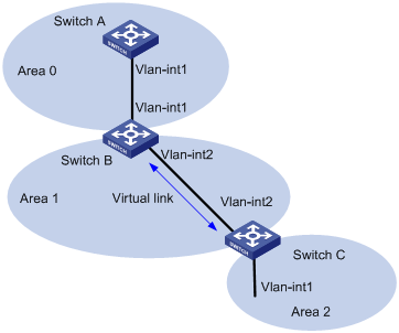
|
Device |
Interface |
IP interface |
Router ID |
|
Switch A |
Vlan-int1 |
196.1.1.1/24 |
1.1.1.1 |
|
Switch B |
Vlan-int1 |
196.1.1.2/24 |
2.2.2.2 |
|
|
Vlan-int2 |
197.1.1.2/24 |
|
|
Switch C |
Vlan-int1 |
152.1.1.1/24 |
3.3.3.3 |
|
|
Vlan-int2 |
197.1.1.1/24 |
|
Configuration procedure
# Configure Switch A.
<SwitchA> system-view
[SwitchA] interface Vlan-interface 1
[SwitchA-Vlan-interface1] ip address 196.1.1.1 255.255.255.0
[SwitchA-Vlan-interface1] quit
[SwitchA] router id 1.1.1.1
[SwitchA] ospf
[SwitchA-ospf-1] area 0
[SwitchA-ospf-1-area-0.0.0.0] network 196.1.1.0 0.0.0.255
# Configure Switch B.
<SwitchB> system-view
[SwitchB] interface vlan-interface 1
[SwitchB-Vlan-interface1] ip address 196.1.1.2 255.255.255.0
[SwitchB-Vlan-interface1] quit
[SwitchB] interface vlan-interface 2
[SwitchB-Vlan-interface2] ip address 197.1.1.2 255.255.255.0
[SwitchB-Vlan-interface2] quit
[SwitchB] router id 2.2.2.2
[SwitchB] ospf
[SwitchB-ospf-1] area 0
[SwitchB-ospf-1-area-0.0.0.0] network 196.1.1.0 0.0.0.255
[SwitchB-ospf-1-area-0.0.0.0] quit
[SwitchB-ospf-1] area 1
[SwitchB-ospf-1-area-0.0.0.1] network 197.1.1.0 0.0.0.255
[SwitchB-ospf-1-area-0.0.0.1] vlink-peer 3.3.3.3
# Configure Switch C.
<SwitchC> system-view
[SwitchC] interface Vlan-interface 1
[SwitchC-Vlan-interface1] ip address 152.1.1.1 255.255.255.0
[SwitchC-Vlan-interface1] quit
[SwitchC] interface Vlan-interface 2
[SwitchC-Vlan-interface2] ip address 197.1.1.1 255.255.255.0
[SwitchC-Vlan-interface2] quit
[SwitchC] router id 3.3.3.3
[SwitchC] ospf
[SwitchC-ospf-1] area 1
[SwitchC-ospf-1-area-0.0.0.1] network 197.1.1.0 0.0.0.255
[SwitchC-ospf-1-area-0.0.0.1] vlink-peer 2.2.2.2
[SwitchC-ospf-1-area-0.0.0.1] quit
[SwitchC-ospf-1] area 2
[SwitchC-ospf-1-area-0.0.0.2] network 152.1.1.0 0.0.0.255
Troubleshooting OSPF Configuration
Unable to Establish a Neighbor Relationship between Routers
Symptom
No neighbor relationship can be established between neighboring routers.
Analysis
1) Verify that the routers work normally at the link layer.
2) Verify that the conditions for establishing a neighbor relationship are satisfied.
l OSPF parameters on the interconnected interfaces must be consistent.
l Area IDs on the interconnected interfaces must be the same.
l Network ID and subnet masks of the interconnected interfaces must be consistent. (P2P networks and virtual link are excluded.)
l The interconnected interfaces have the same type of network.
l If the network type of the interface on the local router is NBMA, a neighbor must be specified by using the peer command.
Solution
Perform the following procedure.
1) Use the display ip interface brief command to verify that the link layer works normally.
2) Use the ping command to check network layer connectivity.
3) Use the display ospf interface command to view the OSPF interface configuration.
4) If the network type of an interface is NBMA, use the display current-configuration configuration ospf command to verify that a neighbor is specified for the router.
5) Use the display ospf brief command to check that the OSPF timers are consistent with those on the neighbor and that the dead time of the neighbor is four times the Hello interval.
6) Use the display ospf peer command to view neighbors.
Unable to Learn a Complete Network Topology
Symptom
The router running OSPF is unable to learn a complete network topology.
Analysis
Perform the following procedure to make analyses:
1) If multiple areas are configured on the router, check that one is specified as the backbone area.
2) Check that the backbone area is fully meshed.
3) Check that the backbone area is not configured as a Stub area or NSSA area.
4) Check that no virtual links are configured for the backbone area.
5) For a Stub area, check that the Stub attributes are configured for all routers in the area.
6) For an NSSA area, check that the NSSA attributes are configured for all routers in the area.
7) Check that Stub or NSSA areas are not a transit area of any virtual link. Virtual links cannot pass through a Stub or NSSA area.
Solution
Perform the following procedure:
1) Use the display ospf peer command to view the OSPF neighbor status.
2) Use the display ospf interface command to view the OSPF configuration on an interface.
3) Use the display ospf lsdb command to view the LSDB information.
4) Use the display current-configuration configuration ospf command to view area configurations.
5) If a virtual link is configured, use the display ospf vlink command to check that the OSPF virtual link is normal.
When configuring an IP route policy, go to these sections for information you are interested in:
l IP Route Policy Configuration Task List
l IP Route Policy Configuration Example
l Troubleshooting IP Route Policy
![]()
The term router in this chapter refers to a router in a generic sense or an Ethernet switch running a routing protocol.
IP Route Policy Overview
Introduction to IP Route Policy
Route policy is technology used to modify routing information to control the forwarding path of data packets. Route policy is implemented by changing the route attributes such as reachability.
When a router distributes or receives routing information, it may need to implement some policies to filter the routing information, so as to receive or distribute only the routing information meeting given conditions. A routing protocol (RIP, for example) may need to import the routing information discovered by other protocols to enrich its routing knowledge. While importing routing information from another protocol, it possibly only needs to import the routes meeting given conditions and control some attributes of the imported routes to make the routes meet the requirements of this protocol.
For the implementation of a route policy, you need to define a set of matching rules by specifying the characteristics of the routing information to be filtered. You can set the rules based on such attributes as destination address and source address of the information. The matching rules can be set in advance and then used in the routing policies to advertise, receive, and import routes.
Filters
A routing protocol can reference an ACL, IP-prefix, or route policy to filter routing information. The following sections describe these filters.
ACL
You can specify a range of IP addresses or subnets when defining an ACL so as to match the destination network addresses or next-hop addresses in routing information. You can reference an ACL into a route policy to filter routing information.
For ACL configuration, refer to the part discussing ACL.
IP-prefix list
IP-prefix list plays a role similar to ACL. But it is more flexible than ACL and easier to understand. When IP-prefix list is applied to filter routing information, its matching object is the destination address field in routing information. Moreover, with IP-prefix list, you can use the gateway option to specify that only routing information advertised by certain routers will be received.
An IP-prefix list is identified by its IP-prefix name. Each IP-prefix list can contain multiple entries, and each entry, identified by an index-number, can independently specify the match range in the network prefix form. An index-number specifies the matching sequence in the IP-prefix list.
There is an OR relationship between entries. During the matching, the router checks entries identified by index-number in ascending order. Once an entry is matched, the IP-prefix list filtering is passed and no other entries will be checked.
Route policy
A route policy is used to match some attributes with given routing information and the attributes of the information will be set if the conditions are satisfied.
A route policy can comprise multiple nodes. Each node is a unit for matching test, and the nodes will be matched in ascending order of their node numbers. Each node comprises a set of if-match and apply clauses. The if-match clauses define the matching rules. The matching objects are some attributes of routing information. The relationship among the if-match clauses for a node is “AND”. As a result, a matching test against a node is successful only when all the matching conditions specified by the if-match clauses in the node are satisfied. The apply clauses specify the actions performed after a matching test against the node is successful, and the actions can be the attribute settings of routing information.
There is an OR relationship between different nodes in a route policy. As a result, the system examines the nodes in the route policy in sequence, and once the route matches a node in the route policy, it will pass the matching test of the route policy without entering the test of the next node.
IP Route Policy Configuration Task List
Complete the following tasks to configure an IP route policy:
|
Task |
Remarks |
|
|
Required |
||
|
Required |
||
|
Required |
||
Route Policy Configuration
A route policy is used to match given routing information or some attributes of routing information and change the attributes of the routing information if the conditions are met. The above-mentioned filtering lists can serve as the match conditions:
A route policy can comprise multiple nodes and each node comprises:
l if-match clause: Defines matching rules; that is, the filtering conditions that the routing information should satisfy for passing the current route policy. The matching objects are some attributes of the routing information.
Configuration Prerequisites
Before configuring a route policy, perform the following tasks:
l Configuring a filtering list,
l Configuring a routing protocol
Prepare the following data before the configuration:
l Route policy name and node number
l Match conditions
l Route attributes to be changed
Defining a Route Policy
Follow these steps to define a route policy:
|
To do... |
Use the command... |
Remarks |
|
Enter system view |
system-view |
— |
|
Define a route policy and enter the route policy view |
route-policy route-policy-name { permit | deny } node node-number |
Required Not defined by default |
![]()
l The permit argument specifies the matching mode for a defined node in the route policy to be in permit mode. If a route matches the rules for the node, the apply clauses for the node will be executed and the test of the next node will not be taken. If not, however, the route takes the test of the next node.
l The deny argument specifies the matching mode for a defined node in the route policy to be in deny mode. In this mode, no apply clause is executed. If a route satisfies all the if-match clauses of the node, no apply clause for the node will be executed and the test of the next node will not be taken. If not, however, the route takes the test of the next node.
l If multiple nodes are defined in a route policy, at least one of them should be in permit mode. When a route policy is applied to filtering routing information, if a piece of routing information does not match any node, the routing information will be denied by the route policy. If all the nodes in the route policy are in deny mode, all routing information will be denied by the route policy.
Defining if-match Clauses and apply Clauses
Follow these steps to define if-match clauses and apply clauses:
|
To do... |
Use the command... |
Remarks |
|
Enter system view |
system-view |
— |
|
Enter the route-policy view |
route-policy route-policy-name { permit | deny } node node-number |
Required |
|
Define a rule to match the IP address of routing information |
if-match { acl acl-number | ip-prefix ip-prefix-name } |
Optional By default, no matching is performed on the address of routing information. |
|
Define a rule to match the cost of routes |
if-match cost value |
Optional By default, no matching is performed against the cost of routes. |
|
Define a rule to match the next-hop interface of routing information |
if-match interface interface-type interface-number |
Optional By default, no matching is performed on the next-hop interface of routing information. |
|
Define a rule to match the next-hop address of routing information |
if-match ip next-hop { acl acl-number | ip-prefix ip-prefix-name } |
Optional By default, no matching is performed on the next-hop address of routing information. |
|
Define a rule to match the tag field of OSPF routing information |
if-match tag value |
Optional By default, no matching is performed on the tag field of OSPF routing information. |
|
Apply a cost to routes satisfying matching rules |
apply cost value |
Optional By default, no cost is applied to routes satisfying matching rules. |
|
Define an action to set the tag field of routing information |
apply tag value |
Optional By default, no action is defined to set the tag field of OSPF routing information. |
![]()
l A route policy comprises multiple nodes. There is an OR relationship between the nodes in a route policy. As a result, the system examines the nodes in sequence, and once the route matches a node in the route policy, it will pass the matching test of the route policy without entering the test of the next node.
l During the matching, there is an AND relationship between the if-match clauses for a route policy node. That is, a matching test against a node is successful only when all the matching conditions specified by the if-match clauses in the node are satisfied.
l If no if-match clauses are specified, all the routes will filter through the node.
l A node can comprise no if-match clause or multiple if-match clauses.
l Each node comprises a set of if-match and apply clauses. if-match clauses define matching rules. apply clauses specify the actions performed after a matching test against the node is successful, and the actions can be the attribute settings of routing information.
IP-Prefix Configuration
Configuration Prerequisites
Before configuring a filter list, prepare the following data:
l IP-prefix name
l Range of addresses to be matched
Configuring an ip-prefix list
An IP-prefix list is identified by its IP-prefix list name. Each IP-prefix list can comprise multiple entries. Each entry can independently specify a match range in the form of network prefix and is identified by an index-number. For example, the following is an IP-prefix list named abcd:
l ip ip-prefix abcd index 10 permit 1.0.0.0 8
l ip ip-prefix abcd index 20 permit 2.0.0.0 8
During the matching of a route, the router checks the entries in ascending order of index-number. Once the route matches an entry, the route passes the filtering of the IP-prefix list and no other entry will be matched.
Follow these steps to configure an IPv4 IP-prefix list:
|
To do... |
Use the command... |
Remarks |
|
Enter system view |
system-view |
— |
|
Configure an IPv4 IP-prefix list |
ip ip-prefix ip-prefix-name [ index index-number ] { permit | deny } network len [ greater-equal greater-equal | less-equal less-equal ] |
Required Not configured by default |
![]()
If all the entries of the IP prefix list are in the deny mode, all routing information will be denied by the filter. In this case, you are recommended to define an entry in the permit mode with the ip ip-prefix ip-prefix-name index index-number permit 0.0.0.0 0 less-equal 32 command following multiple entries in the deny mode to permit all the other IP routes.
Displaying IP Route Policy
|
To do... |
Use the command... |
Remarks |
|
Display route policy information |
display route-policy [ route-policy-name ] |
Available in any view |
|
Display IP-prefix information |
display ip ip-prefix [ ip-prefix-name ] |
IP Route Policy Configuration Example
Configuring to Filter Received Routing Information
Network requirements
Switch A communicates with Switch B. OSPF protocol is enabled on both switches. The router ID of Switch A is 1.1.1.1 and that of Switch B is 2.2.2.2.
Configure three static routes and enable OSPF on Switch A.
By configuring route filtering rules on Switch A make the three received static routes partially visible and partially shielded: the routes of network segments 20.0.0.0 and 40.0.0.0 are visible, and the route of network segment 30.0.0.0 is shielded.
Network diagram
Figure 5-1 Filter received routing information
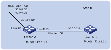
Configuration procedure
l Configure Switch A:
# Configure the IP addresses of the interfaces.
<SwitchA> system-view
[SwitchA] interface vlan-interface 100
[SwitchA-Vlan-interface100] ip address 10.0.0.1 255.0.0.0
[SwitchA-Vlan-interface100] quit
[SwitchA] interface vlan-interface 200
[SwitchA-Vlan-interface200] ip address 12.0.0.1 255.0.0.0
[SwitchA-Vlan-interface200] quit
# Configure three static routes.
[SwitchA] ip route-static 20.0.0.0 255.0.0.0 12.0.0.2
[SwitchA] ip route-static 30.0.0.0 255.0.0.0 12.0.0.2
[SwitchA] ip route-static 40.0.0.0 255.0.0.0 12.0.0.2
# Enable the OSPF protocol and specify the ID of the area to which the interface 10.0.0.1 belongs.
<SwitchA> system-view
[SwitchA] router id 1.1.1.1
[SwitchA] ospf
[SwitchA-ospf-1] area 0
[SwitchA-ospf-1-area-0.0.0.0] network 10.0.0.0 0.255.255.255
[SwitchA-ospf-1-area-0.0.0.0] quit
[SwitchA-ospf-1]quit
# Configure an ACL.
[SwitchA] acl number 2000
[SwitchA-acl-basic-2000] rule deny source 30.0.0.0 0.255.255.255
[SwitchA-acl-basic-2000] rule permit source any
[SwitchA-acl-basic-2000] quit
# Configure a route policy.
[SwitchA] route-policy ospf permit node 10
[SwitchA-route-policy] if-match acl 2000
[SwitchA-route-policy] quit
# Apply route policy when the static routes are imported.
[SwitchA] ospf
[SwitchA-ospf-1] import-route static route-policy ospf
l Configure Switch B:
# Configure the IP address of the interface.
<SwitchB> system-view
[SwitchB] interface vlan-interface 100
[SwitchB-Vlan-interface100] ip address 10.0.0.2 255.0.0.0
[SwitchB-Vlan-interface100] quit
# Enable the OSPF protocol and specify the ID of the area to which the interface belongs.
[SwitchB] router id 2.2.2.2
[SwitchB] ospf
[SwitchB-ospf-1] area 0
[SwitchB-ospf-1-area-0.0.0.0] network 10.0.0.0 0.255.255.255
[SwitchB-ospf-1-area-0.0.0.0] quit
[SwitchB-ospf-1] quit
l Display the OSPF routing table on Switch B and check if route policy takes effect.
<SwitchB> display ospf routing
OSPF Process 1 with Router ID 2.2.2.2
Routing Tables
Routing for Network
Destination Cost Type NextHop AdvRouter Area
10.0.0.0/8 1 Transit 10.0.0.2 1.1.1.1 0.0.0.0
Routing for ASEs
Destination Cost Type Tag NextHop AdvRouter
20.0.0.0/8 1 Type2 1 10.0.0.1 1.1.1.1
40.0.0.0/8 1 Type2 1 10.0.0.1 1.1.1.1
Total Nets: 3
Intra Area: 1 Inter Area: 0 ASE: 2 NSSA: 0
Controlling RIP Packet Cost to Implement Dynamic Route Backup
Network requirements
The required speed of convergence in the small network of a company is not high. The network provides two services. Main and backup links are provided for each service for the purpose of reliability. The main link of one service serves as the backup link of the other. The two services are distinguished by IP addresses. If a fault occurs to the main link of one service, dynamic backup can prevent service interruption.
Network diagram
According to the network requirements, the network topology is designed as shown in Figure 5-2.
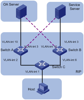
|
Device |
Interface |
IP address |
|
Switch A |
Vlan-int 2 |
2.2.2.1/8 |
|
|
Vlan-int 3 |
3.3.3.254/8 |
|
|
Vlan-int 10 |
1.1.1.254/8 |
|
Switch B |
Vlan-int 3 |
3.3.3.253/8 |
|
|
Vlan-int 6 |
6.6.6.5/8 |
|
|
Vlan-int 10 |
1.1.1.253/8 |
|
Switch C |
Vlan-int 1 |
192.168.0.39/24 |
|
|
Vlan-int 2 |
2.2.2.2/8 |
|
|
Vlan-int 6 |
6.6.6.6/8 |
|
OA Server |
|
1.1.1.1/32 |
|
Service Server |
|
3.3.3.3/32 |
|
Host |
|
192.168.0.9/24 |
Configuration considerations
l According to the network requirements, select RIP.
l For the OA server, the main link is between Switch A and Switch C, while the backup link is between Switch B and Switch C.
l For the service server, the main link is between Switch B and Switch C, while the backup link is between Switch A and Switch C.
l Apply a route policy to control the cost of routes received by Switch C to provide main and backup links for the services of the OA server and service server.
Configuration procedure
1) Configure Switch A.
# Create VLANs and configure IP addresses for the VLAN interfaces. The configuration procedure is omitted.
# Configure RIP.
<SwitchA> system-view
[SwitchA] rip
[SwitchA-rip] network 1.0.0.0
[SwitchA-rip] network 2.0.0.0
[SwitchA-rip] network 3.0.0.0
2) Configure Switch B.
# Create VLANs and configure IP addresses for the VLAN interfaces. The configuration procedure is omitted.
# Configure RIP.
<SwitchB> system-view
[SwitchB] rip
[SwitchB-rip] network 1.0.0.0
[SwitchB-rip] network 3.0.0.0
[SwitchB-rip] network 6.0.0.0
3) Configure Switch C.
# Create VLANs and configure IP addresses for the VLAN interfaces. The configuration procedure is omitted.
# Define IP-prefix 1 containing the IP address prefix 1.0.0.0/8, and IP-prefix 2 containing the IP address prefix 3.0.0.0/8.
<SwitchC> system-view
[SwitchC] ip ip-prefix 1 index 10 permit 1.0.0.0 8
[SwitchC] ip ip-prefix 2 index 10 permit 3.0.0.0 8
# Create a route policy named in and node 10 with the matching mode being permit. Define if-match clauses. Apply the cost 5 to routes matching the outgoing interface VLAN-interface 2 and prefix list 1.
[SwitchC] route-policy in permit node 10
[SwitchC-route-policy] if-match interface Vlan-interface2
[SwitchC-route-policy] if-match ip-prefix 1
[SwitchC-route-policy] apply cost 5
[SwitchC-route-policy] quit
# Create node 20 with the matching mode being permit in the route policy. Define if-match clauses. Apply the cost 6 to routes matching the outgoing interface VLAN-interface 2 and prefix list 2.
[SwitchC] route-policy in permit node 20
[SwitchC-route-policy] if-match interface Vlan-interface2
[SwitchC-route-policy] if-match ip-prefix 2
[SwitchC-route-policy] apply cost 6
[SwitchC-route-policy] quit
# Create node 30 with the matching mode being permit in the route policy. Define if-match clauses. Apply the cost 6 to routes matching the outgoing interface VLAN-interface 6 and prefix list 1.
[SwitchC] route-policy in permit node 30
[SwitchC-route-policy] if-match interface Vlan-interface6
[SwitchC-route-policy] if-match ip-prefix 1
[SwitchC-route-policy] apply cost 6
[SwitchC-route-policy] quit
# Create node 40 with the matching mode being permit in the route policy. Define if-match clauses. Apply the cost 5 to routes matching the outgoing interface VLAN-interface 6 and prefix list 2.
[SwitchC] route-policy in permit node 40
[SwitchC-route-policy] if-match interface Vlan-interface6
[SwitchC-route-policy] if-match ip-prefix 2
[SwitchC-route-policy] apply cost 5
[SwitchC-route-policy] quit
# Create node 50 with the matching mode being permit, to allow all routing information to pass.
[SwitchC] route-policy in permit node 50
[SwitchC-route-policy] quit
# Configure RIP and apply the route policy in to the incoming routing information.
[SwitchC] rip
[SwitchC-rip] network 1.0.0.0
[SwitchC-rip] network 3.0.0.0
[SwitchC-rip] network 6.0.0.0
[SwitchC-rip] filter-policy route-policy in import
Configuration verification
1) Display data forwarding paths when the main link of the OA server between Switch A and Switch C works normally.
<SwitchC> display ip routing-table
Routing Table: public net
Destination/Mask Protocol Pre Cost Nexthop Interface
1.0.0.0/8 RIP 100 5 2.2.2.1 Vlan-interface2
2.0.0.0/8 DIRECT 0 0 2.2.2.2 Vlan-interface2
2.2.2.2/32 DIRECT 0 0 127.0.0.1 InLoopBack0
3.0.0.0/8 RIP 100 5 6.6.6.5 Vlan-interface6
6.0.0.0/8 DIRECT 0 0 6.6.6.6 Vlan-interface6
6.6.6.6/32 DIRECT 0 0 127.0.0.1 InLoopBack0
127.0.0.0/8 DIRECT 0 0 127.0.0.1 InLoopBack0
127.0.0.1/32 DIRECT 0 0 127.0.0.1 InLoopBack0
192.168.0.0/24 DIRECT 0 0 192.168.0.39 Vlan-interface1
192.168.0.39/32 DIRECT 0 0 127.0.0.1 InLoopBack0
2) Display data forwarding paths when the main link of the OA server between Switch A and Switch C is down.
<SwitchC> display ip routing-table
Routing Table: public net
Destination/Mask Protocol Pre Cost Nexthop Interface
1.0.0.0/8 RIP 100 6 6.6.6.5 Vlan-interface2
3.0.0.0/8 RIP 100 5 6.6.6.5 Vlan-interface6
6.0.0.0/8 DIRECT 0 0 6.6.6.6 Vlan-interface6
6.6.6.6/32 DIRECT 0 0 127.0.0.1 InLoopBack0
127.0.0.0/8 DIRECT 0 0 127.0.0.1 InLoopBack0
127.0.0.1/32 DIRECT 0 0 127.0.0.1 InLoopBack0
192.168.0.0/24 DIRECT 0 0 192.168.0.39 Vlan-interface1
192.168.0.39/32 DIRECT 0 0 127.0.0.1 InLoopBack0
Precautions
1) When you configure the apply cost command in a route policy:
l The new cost should be greater than the original one to prevent RIP from generating routing loop in the case that a loop exists in the topology.
l The cost will become 16 if you try to set it to a value greater than 16.
l The cost will become the original one if you try to set it to 0.
l The cost will still be 16 if you try to set it to 16.
2) Using the if-match interface command will match the routes whose outgoing interface to the next hop is the specified interface.
3) You are recommended to configure a node to match all routes not passing the preceding nodes in a route policy.
4) If the cost of a received RIP route is equal to 16, the cost specified by the apply cost command in a route policy will not be applied to the route, that is, the cost of the route is equal to 16.
5) Using the filter-policy command does not filter redistributed routes.
Troubleshooting IP Route Policy
Symptom
The route policy cannot filter routing information correctly when the routing protocol runs normally.
Analysis
The route policy cannot filter routing information correctly in the following two cases:
l All nodes in the route policy are in the deny mode.
l All entries in the IP-prefix list are in the deny mode.
Solution
1) Use the display ip ip-prefix command to display the configuration of the IP-prefix list.
2) Use the display route-policy command to display the configuration of the route policy.
When configuring route capacity, go to these sections for information you are interested in:
l Route Capacity Configuration Overview
l Route Capacity Limitation Configuration
l Displaying and Maintaining Route Capacity Limitation Configuration
![]()
l The term router in this chapter refers to a router in a generic sense or an Ethernet switch running a routing protocol.
l The S3600-SI series do not support route capacity configuration.
Route Capacity Configuration Overview
Introduction
In practical networking applications, there are a large number of routes, especially OSPF routes, in the routing table. Normally, routing information is stored in the memory of the switch. While the size of the routing table increases, the total memory of the switch remains unchanged unless the hardware is upgraded. However, upgrading may not always solve the problem.
To solve this problem, the switches provide a mechanism to control the size of the routing table; that is, monitoring the free memory in the system to determine whether to add new routes to the routing table and whether to keep the connection of a routing protocol.
![]()
Normally, the default configuration of the system can meet the requirements. To avoid decreasing system stability and availability due to improper configuration, it is not recommended to modify the configuration.
Route Capacity Limitation
Huge routing tables are usually caused by OSPF route entries. Therefore, the route capacity limitation of a switch applies only to OSPF routes, instead of static routes and RIP routes. The route capacity limitation is implemented by controlling the size of the free memory of the switch.
When the free memory of the switch is equal to or lower than the lower limit, OSPF connection will be disconnected and OSPF routes will be removed from the routing table.
l If automatic protocol connection recovery is enabled, when the free memory of the switch restores to a value larger than the safety value, the switch automatically re-establishes the OSPF connection.
l If the automatic protocol connection recovery function is disabled, the switch will not reestablish the disconnected OSPF connection even when the free memory restores to a value larger than the safety value.
Route Capacity Limitation Configuration
Route capacity limitation configuration includes:
l Configuring the lower limit and the safety value of switch memory,
l Enabling/disabling the switch to recover the disconnected routing protocol automatically.
Configuring the Lower Limit and the Safety Value of the Switch Memory
Follow these steps to set the lower limit and the safety value of switch memory:
|
To do... |
Use the command... |
Remarks |
|
Enter system view |
system-view |
— |
|
Set the lower limit and the safety value of switch memory |
memory { safety safety-value | limit limit-value }* |
Optional By default l safety-value is 5 l limit-value is 4 |
![]()
The safety-value must be greater than the lower limit-value.
Enabling/Disabling Automatic Protocol Recovery
Follow these steps to enable automatic protocol recovery:
|
To do... |
Use the command... |
Remarks |
|
Enter system view |
system-view |
— |
|
Enable automatic protocol recovery |
memory auto-establish enable |
Optional Enabled by default |
Follow these steps to disable automatic protocol recovery:
|
To do... |
Use the command... |
Remarks |
|
Enter system view |
system-view |
— |
|
Disable automatic protocol recovery |
memory auto-establish disable |
Optional Enabled by default. |
![]()
If automatic protocol recovery is disabled, the OSPF connection will not recover even when the free memory exceeds the safety value. Therefore, take cautions when disabling the function.
Displaying and Maintaining Route Capacity Limitation Configuration
Follow these steps to display route capacity configuration:
|
To do... |
Use the command... |
Remarks |
|
Display memory occupancy of a switch |
display memory [ unit unit-id ] |
Available in any view |
|
Display the route capacity related memory setting and state information |
display memory limit |