- Table of Contents
-
- H3C S6805 & S6825 & S6850 & S9850 & S9820 Config Examples-Release 66xx-6W100
- 01-Login Management Configuration Examples
- 02-RBAC Configuration Examples
- 03-Software Upgrade Examples
- 04-ISSU Configuration Examples
- 05-Software Patching Examples
- 06-Ethernet Link Aggregation Configuration Examples
- 07-Port Isolation Configuration Examples
- 08-Spanning Tree Configuration Examples
- 09-VLAN Configuration Examples
- 10-VLAN Tagging Configuration Examples
- 11-DHCP Snooping Configuration Examples
- 12-Cross-Subnet Dynamic IP Address Allocation Configuration Examples
- 13-IPv6 over IPv4 Manual Tunneling with OSPFv3 Configuration Examples
- 14-ISATAP Tunnel and 6to4 Tunnel Configuration Examples
- 15-GRE Tunnel Configuration Examples
- 16-GRE with OSPF Configuration Examples
- 17-OSPF Configuration Examples
- 18-IS-IS Configuration Examples
- 19-BGP Configuration Examples
- 20-Policy-Based Routing Configuration Examples
- 21-OSPFv3 Configuration Examples
- 22-IPv6 IS-IS Configuration Examples
- 23-Routing Policy Configuration Examples
- 24-IGMP Snooping Configuration Examples
- 25-IGMP Configuration Examples
- 26-BIDIR-PIM Configuration Examples
- 27-MLD Snooping Configuration Examples
- 28-IPv6 Multicast VLAN Configuration Examples
- 29-Basic MPLS Configuration Examples
- 30-MPLS L3VPN Configuration Examples
- 31-ACL Configuration Examples
- 32-Control Plane-Based QoS Policy Configuration Examples
- 33-Traffic Policing Configuration Examples
- 34-GTS and Rate Limiting Configuration Examples
- 35-Priority Mapping and Queue Scheduling Configuration Examples
- 36-Traffic Filtering Configuration Examples
- 37-AAA Configuration Examples
- 38-Port Security Configuration Examples
- 39-Portal Configuration Examples
- 40-SSH Configuration Examples
- 41-IP Source Guard Configuration Examples
- 42-Ethernet OAM Configuration Examples
- 43-CFD Configuration Examples
- 44-DLDP Configuration Examples
- 45-VRRP Configuration Examples
- 46-BFD Configuration Examples
- 47-NTP Configuration Examples
- 48-SNMP Configuration Examples
- 49-NQA Configuration Examples
- 50-Mirroring Configuration Examples
- 51-sFlow Configuration Examples
- 52-FCoE Configuration Examples
- 53-OpenFlow Configuration Examples
- 54-MAC Address Table Configuration Examples
- 55-Static Multicast MAC Address Entry Configuration Examples
- 56-IP Unnumbered Configuration Examples
- 57-MVRP Configuration Examples
- 58-MCE Configuration Examples
- 59-Congestion Avoidance and Queue Scheduling Configuration Examples
- 60-Attack Protection Configuration Examples
- 61-Smart Link Configuration Examples
- 62-RRPP Configuration Examples
- 63-BGP Route Selection Configuration Examples
- 64-IS-IS Route Summarization Configuration Examples
- 65-IRF Configuration Examples
- 66-MPLS OAM Configuration Examples
- 67-MPLS TE Configuration Examples
- 68-VXLAN Configuration Examples
- 69-NetStream Configuration Examples
- 70-DRNI Configuration Examples
- 71-DRNI and EVPN Configuration Examples
- 72-EVPN-DCI over an MPLS L3VPN Network Configuration Examples
- 73-VCF Fabric Configuration Examples
- 74-PTP Configuration Examples
- 75-S-MLAG Configuration Examples
- 76-Puppet Configuration Examples
- 77-802.1X Configuration Examples
- 78-MAC Authentication Configuration Examples
- 79-MOD and Elephant and Mice Flow Configuration Examples
- 80-TCB Configuration Examples
- 81-Multicast VPN Configuration Examples
- Related Documents
-
| Title | Size | Download |
|---|---|---|
| 79-MOD and Elephant and Mice Flow Configuration Examples | 229.30 KB |
|
|
|
H3C S6805 & S6825 &S6850 & S9850 & S9820 |
|
MOD and Elephant and Mice Flow Configuration Examples |
|
|
Copyright © 2020-2023 New H3C Technologies Co., Ltd. All rights reserved.
No part of this manual may be reproduced or transmitted in any form or by any means without prior written consent of New H3C Technologies Co., Ltd.
Except for the trademarks of New H3C Technologies Co., Ltd., any trademarks that may be mentioned in this document are the property of their respective owners.
The information in this document is subject to change without notice.
Contents
General restrictions and guidelines
Applicable hardware and software versions
Configuring Device B, Device C, Device D, and Device E
Verifying the configuration on Device A
Verifying the configuration on Device B, Device C, Device D, and Device E
Analyzing MOD packets received by the collector
Example: Configuring simple MOD
Applicable hardware and software versions
Configuring Device B, Device C, Device D, and Device E
Verifying the configuration on Device A
Verifying the configuration on Device B, Device C, Device D, and Device E
Analyzing MOD packets received by the collector
Example: Distinguishing elephant and mice flows
Applicable hardware and software versions
Configuring Device B, Device C, Device D, and Device E
Verifying the configuration on Device A
Verifying the configuration on Device B, Device C, Device D, and Device E
Observing traffic sending during congestion
Introduction
Mirror On Drop (MOD) can detect packet drops during the forwarding process on the device. When a packet is dropped, MOD can send the packet drop reason and the characteristics of the dropped packet to the collector.
Distinguishing elephant and mice flows can identify elephant flows and assign a high drop precedence, local precedence, or 802.1p priority value to these flows, thus improving application performance for mice flows.
This document provides examples for configuring MOD and for configuring elephant/mice flow distinguishing.
Prerequisites
The configuration examples in this document were created and verified in a lab environment, and all the devices were started with the factory default configuration. When you are working on a live network, make sure you understand the potential impact of every command on your network.
This document assumes that you have basic knowledge of MOD and elephant and mice flow distinguishing.
General restrictions and guidelines
When you configure MOD follow these restrictions and guidelines:
· A flow group can reference only one ACL. An ACL referenced by a flow group supports only the 5-tuple (source IP address, destination IP address, source port number, destination port number, and protocol) and DSCP priority match items.
· Because a flow can belong to only one flow group, make sure the same flow is not assigned to more than one flow group when specifying ACLs.
· MOD takes effect only on packets matching ACLs referenced by flow groups.
· To delete an applied flow group, first remove the application and then delete the flow group.
· Only one flow group can be applied.
· You cannot modify the name or mode of an existing flow group.
Example: Configuring MOD
Network configuration
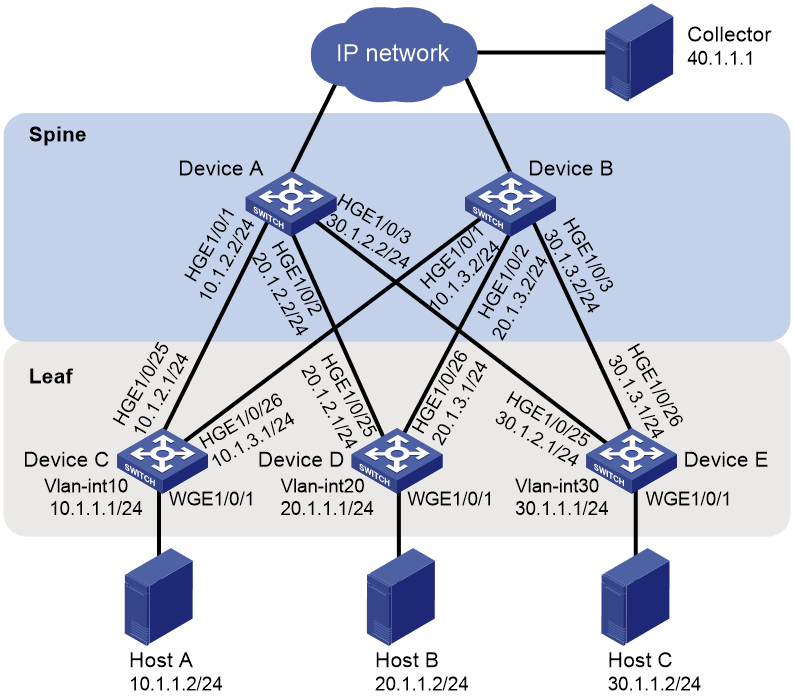
As shown in Figure 1, the network uses a spine-leaf architecture. Configure MOD on the spine device and leaf devices to identify whether packets are dropped during the forwarding process on the devices.

Analysis
To generate flow entries based on the flow group, configure the flow group mode to MOD.
Configure MOD to monitor packet drops based on the reason list.
Configure MOD sampling to send sampled packets to the collector through UDP.
Applicable hardware and software versions
The following matrix shows the hardware and software versions to which this configuration example is applicable:
|
Hardware |
Software version |
|
S6805 switch series |
Release 6616, Release 6616P01, Release 6635 and later |
|
S6825 switch series |
Release 6616, Release 6616P01, Release 6635 and later |
|
S6850 switch series S9850 switch series |
Release 6616, Release 6616P01, Release 6635 and later |
|
S9820-64H switch |
Release 6616, Release 6616P01, Release 6635 and later |
|
S9820-8C switch |
Not supported |
Prerequisites
# Set the hardware resource operating mode to EM, save the configuration, and reboot the device.
<DeviceA> system-view
[DeviceA] hardware-resource switch-mode EM
Do you want to change the specified hardware resource working mode? [Y/N]:y
The hardware resource working mode is changed, please save the configuration and reboot the system to make it effective.
You can use the display hardware-resource switch-mode command to view the hardware resource operating mode.
# Configure the hardware resource operating mode on Device B, Device C, Device D, and Device E in the same way it is configured on Device A.
Procedures
Configuring Device A
Configuring IP addresses for interfaces
# Configure interfaces HundredGigE 1/0/1 through HundredGigE 1/0/3 to operate in Layer 3 mode, and configure an IP address for each interface.
<DeviceA> system-view
[DeviceA] interface hundredgige 1/0/1
[DeviceA-HundredGigE1/0/1] port link-mode route
[DeviceA-HundredGigE1/0/1] ip address 10.1.2.2 24
[DeviceA-HundredGigE1/0/1] quit
[DeviceA] interface hundredgige 1/0/2
[DeviceA-HundredGigE1/0/2] port link-mode route
[DeviceA-HundredGigE1/0/2] ip address 20.1.2.2 24
[DeviceA-HundredGigE1/0/2] quit
[DeviceA] interface hundredgige 1/0/3
[DeviceA-HundredGigE1/0/3] port link-mode route
[DeviceA-HundredGigE1/0/3] ip address 30.1.2.2 24
[DeviceA-HundredGigE1/0/3] quit
Configuring a routing protocol
# Configure OSPF.
[DeviceA] ospf 1 router-id 1.1.1.1
[DeviceA-ospf-1] area 0
[DeviceA-ospf-1-area-0.0.0.0] network 10.1.2.0 0.0.0.255
[DeviceA-ospf-1-area-0.0.0.0] network 20.1.2.0 0.0.0.255
[DeviceA-ospf-1-area-0.0.0.0] network 30.1.2.0 0.0.0.255
[DeviceA-ospf-1-area-0.0.0.0] quit
[DeviceA-ospf-1] quit
Configuring a flow group
# Create advanced IPv4 ACL 3000, and configure a rule to match packets with destination IP address 10.0.0.10 for the ACL.
[DeviceA] acl advanced 3000
[DeviceA-acl-ipv4-adv-3000] rule permit ip destination 30.1.1.2 0
[DeviceA-acl-ipv4-adv-3000] quit
# Create flow group 1 in MOD mode and configure it to reference ACL 3000.
[DeviceA] telemetry flow-group 1
[DeviceA-telemetry-flow-group-1] if-match acl 3000
# Configure the flow group to generate flow entries based on the destination IP address.
[DeviceA-telemetry-flow-group-1] template destination-ip
[DeviceA-telemetry-flow-group-1] quit
# Set the flow entry aging time to 10 minutes.
[DeviceA] telemetry flow-group aging-time 10
# Apply flow group 1.
[DeviceA] telemetry apply flow-group 1
Configuring MOD
# Configure the device ID for MOD as 10.1.2.2.
[DeviceA] telemetry mod
[DeviceA-telemetry-mod] device-id 10.1.2.2
[DeviceA-telemetry-mod] quit
# Create sampler samp, set the sampling mode to random, and set the sampling rate to 2 to the 8th power.
[DeviceA] sampler samp mode random packet-interval n-power 8
# Enable sampling for MOD, and reference sampler samp.
[DeviceA] telemetry mod
[DeviceA-telemetry-mod] sampler samp
# Specify UDP for MOD to use to send packets to the collector.
[DeviceA-telemetry-mod] transport-protocol udp
# Encapsulate the packets sent to the collector by MOD with the following information: source IP address 10.1.2.2, destination IP address 40.1.1.1, source port number 1000, and destination port number 2333.
[DeviceA-telemetry-mod] collector source-ip 10.1.2.2 destination-ip 40.1.1.1 source-port 1000 destination-port 2333
# Configure MOD to monitor all packet drop reasons.
[DeviceA-telemetry-mod] reason-list all
[DeviceA-telemetry-mod] quit
[DeviceA] quit
Configuring Device B, Device C, Device D, and Device E
# Configure Device B, Device C, Device D, and Device E in the same way Device A is configured except for the following items:
· Interface IP addresses.
· OSPF router ID and network segments.
· Device ID for MOD.
· Source IP address encapsulated in the packets sent to the collector.
Verifying the configuration
Verifying the configuration on Device A
# Display the ACL configuration.
<DeviceA> display acl 3000
Advanced IPv4 ACL 3000, 1 rule,
ACL's step is 5, start ID is 0
rule 0 permit ip destination 30.1.1.2 0
# Display the flow group configuration.
<DeviceA> display telemetry flow-group 1
Flow group 1 (Successful)
ACL : 3000
Template : destination-ip
Mode : MOD
Aging time: 10 minutes
Rate limit: -
Max-entry : -
# Display the MOD configuration.
<DeviceA> display telemetry mod
Status : Successful
Drop reason list:
ipv4-dip-miss
ip-multicast-error
unknown-vlan
ipv4-l3-header-error
tunnel-header-error
parity-error
higig-header-error
invalid-tpid
Sampler : samp
Device ID : 10.1.2.2
Transport protocol : UDP
Collector
Source IP : 10.1.2.2
Destination IP : 40.1.1.1
Source port : 1000
Destination port : 2333
Verifying the configuration on Device B, Device C, Device D, and Device E
The configurations on Device B, Device C, Device D, and Device E are the same as the configuration on Device A except for interface IP addresses, OSPF router ID and network segments, the device ID for MOD, and the source IP address encapsulated in the packets sent to the collector. (Details not shown.)
Analyzing MOD packets received by the collector
# Ping Host C from Device A.
<DeviceA> ping 30.1.1.2
Ping 30.1.1.2 (30.1.1.2): 56 data bytes, press CTRL+C to break
56 bytes from 30.1.1.2: icmp_seq=0 ttl=255 time=4.703 ms
56 bytes from 30.1.1.2: icmp_seq=1 ttl=255 time=1.636 ms
56 bytes from 30.1.1.2: icmp_seq=2 ttl=255 time=1.733 ms
56 bytes from 30.1.1.2: icmp_seq=3 ttl=255 time=1.662 ms
56 bytes from 30.1.1.2: icmp_seq=4 ttl=255 time=1.606 ms
--- Ping statistics for 30.1.1.2 ---
5 packet(s) transmitted, 5 packet(s) received, 0.0% packet loss
round-trip min/avg/max/std-dev = 1.606/2.268/4.703/1.218 ms
# Modify the configuration of Device E.
<DeviceE> system-view
[DeviceE] ospf 1
[DeviceE-ospf-1] area 0
[DeviceE-ospf-1-area-0.0.0.0] undo network 30.1.2.0 0.0.0.255
[DeviceE-ospf-1-area-0.0.0.0] quit
[DeviceE-ospf-1] quit
# Ping Host C from Device A.
<DeviceA> ping 30.1.1.2
Ping 30.1.1.2 (30.1.1.2): 56 data bytes, press CTRL+C to break
Request time out
Request time out
Request time out
Request time out
Request time out
--- Ping statistics for 30.1.1.2 ---
5 packet(s) transmitted, 0 packet(s) received, 100.0% packet loss
When a packet destined for Host C is dropped during the forwarding process on the spine device and leaf devices, the collector can receive the packet drop reason and the characteristics of the dropped packet from the devices.
In this example, the packet drop information received by the collector showed that Device A dropped packets and the packet drop reason is ipv4-dip-miss. This indicates that there is no route on Device A to Host C. After you recover the OSPF configuration on Device E, Host C can receive the packets.
Configuration files
· Device A:
#
ospf 1 router-id 1.1.1.1
area 0.0.0.0
network 10.1.2.0 0.0.0.255
network 20.1.2.0 0.0.0.255
network 30.1.2.0 0.0.0.255
#
interface HundredGigE1/0/1
port link-mode route
ip address 10.1.2.2 255.255.255.0
#
interface HundredGigE1/0/2
port link-mode route
ip address 20.1.2.2 255.255.255.0
#
interface HundredGigE1/0/3
port link-mode route
ip address 30.1.2.2 255.255.255.0
#
sampler samp mode random packet-interval n-power 8
#
acl advanced 3000
rule 0 permit ip destination 30.1.1.2 0
#
telemetry mod
reason-list all
device-id 10.1.2.2
sampler samp
collector source-ip 10.1.2.2 destination-ip 40.1.1.1 source-port 1000 destination-port 2333
#
telemetry flow-group 1 mode mod
if-match acl 3000
template destination-ip
#
telemetry apply flow-group 1
telemetry flow-group aging-time 10
#
· Device B, Device C, Device D, and Device E:
The configurations on Device B, Device C, Device D, and Device E are the same as the configuration on Device A except for interface IP addresses, OSPF router ID and network segments, the device ID for MOD, and the source IP address encapsulated in the packets sent to the collector. (Details not shown.)
Example: Configuring simple MOD
Network configuration
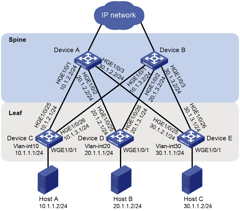
As shown in Figure 2, the network uses a spine-leaf architecture. Configure simple MOD on the spine device and leaf devices to identify whether packets are dropped during the forwarding process on the devices.
Analysis
To generate flow entries based on the flow group, configure the flow group mode to simple MOD.
Configure simple MOD to monitor packet drops based on the reason list.
Applicable hardware and software versions
The following matrix shows the hardware and software versions to which this configuration example is applicable:
|
Hardware |
Software version |
|
S6805 switch series |
Release 6616, Release 6616P01, Release 6635 and later |
|
S6825 switch series |
Release 6616, Release 6616P01, Release 6635 and later |
|
S6850 switch series S9850 switch series |
Release 6616, Release 6616P01, Release 6635 and later |
|
S9820-64H switch |
Release 6616, Release 6616P01, Release 6635 and later |
|
S9820-8C switch |
Release 6616, Release 6616P01, Release 6635 and later |
Procedures
Configuring Device A
Configuring IP addresses for interfaces
# Configure interfaces HundredGigE 1/0/1 through HundredGigE 1/0/3 to operate in Layer 3 mode, and configure an IP address for each interface.
<DeviceA> system-view
[DeviceA] interface hundredgige 1/0/1
[DeviceA-HundredGigE1/0/1] port link-mode route
[DeviceA-HundredGigE1/0/1] ip address 10.1.2.2 24
[DeviceA-HundredGigE1/0/1] quit
[DeviceA] interface hundredgige 1/0/2
[DeviceA-HundredGigE1/0/2] port link-mode route
[DeviceA-HundredGigE1/0/2] ip address 20.1.2.2 24
[DeviceA-HundredGigE1/0/2] quit
[DeviceA] interface hundredgige 1/0/3
[DeviceA-HundredGigE1/0/3] port link-mode route
[DeviceA-HundredGigE1/0/3] ip address 30.1.2.2 24
[DeviceA-HundredGigE1/0/3] quit
Configuring a routing protocol
# Configure OSPF.
[DeviceA] ospf 1 router-id 1.1.1.1
[DeviceA-ospf-1] area 0
[DeviceA-ospf-1-area-0.0.0.0] network 10.1.2.0 0.0.0.255
[DeviceA-ospf-1-area-0.0.0.0] network 20.1.2.0 0.0.0.255
[DeviceA-ospf-1-area-0.0.0.0] network 30.1.2.0 0.0.0.255
[DeviceA-ospf-1-area-0.0.0.0] quit
[DeviceA-ospf-1] quit
Configuring a flow group
# Create advanced IPv4 ACL 3000, and configure a rule to match packets with destination IP address 10.0.0.10 for the ACL.
[DeviceA] acl advanced 3000
[DeviceA-acl-ipv4-adv-3000] rule permit ip destination 30.1.1.2 0
[DeviceA-acl-ipv4-adv-3000] quit
# Create flow group 2 in simple MOD mode and configure it to reference ACL 3000.
[DeviceA] telemetry flow-group 2 mode simple-mod
[DeviceA-telemetry-flow-group-2] if-match acl 3000
# Configure the flow group to generate flow entries based on the destination IP address.
[DeviceA-telemetry-flow-group-2] template destination-ip
[DeviceA-telemetry-flow-group-2] quit
# Set the flow entry aging time to 10 minutes.
[DeviceA] telemetry flow-group aging-time 10
# Apply flow group 2.
[DeviceA] telemetry apply flow-group 2
Configuring simple MOD
# Configure the device ID for simple MOD as 10.1.2.2.
[DeviceA] telemetry mod
[DeviceA-telemetry-mod] device-id 10.1.2.2
# Specify UDP for simple MOD to use to send packets to the collector.
[DeviceA-telemetry-mod] transport-protocol udp
# Encapsulate the packets sent to the collector by simple MOD with the following information: source IP address 10.1.2.2, destination IP address 40.1.1.1, source port number 1000, and destination port number 2333.
[DeviceA-telemetry-mod] collector source-ip 10.1.2.2 destination-ip 40.1.1.1 source-port 1000 destination-port 2333
# Configure simple MOD to monitor all packet drop reasons.
[DeviceA-telemetry-mod] reason-list all
[DeviceA-telemetry-mod] quit
[DeviceA] quit
Configuring Device B, Device C, Device D, and Device E
# Configure Device B, Device C, Device D, and Device E in the same way Device A is configured except for the following items:
· Interface IP addresses.
· OSPF router ID and network segments.
Device ID for simple MOD.
Source IP address encapsulated in the packets sent to the collector.
Verifying the configuration
Verifying the configuration on Device A
# Display the ACL configuration.
<DeviceA> display acl 3000
Advanced IPv4 ACL 3000, 1 rule,
ACL's step is 5, start ID is 0
rule 0 permit ip destination 30.1.1.2 0
# Display the flow group configuration.
<Device> display telemetry flow-group 2
Flow group 2 (Successful)
ACL : 3000
Template : destination-ip
Mode : Simple MOD
Aging time: 10 minutes
Rate limit: -
Max-entry : -
# Display the simple MOD configuration.
<DeviceA> display telemetry mod
Status : Successful
Drop reason list:
ipv4-dip-miss
ip-multicast-error
unknown-vlan
tunnel-header-error
parity-error
higig-header-error
Device ID : 10.1.2.2
Transport protocol : UDP
Collector
Source IP : 10.1.2.2
Destination IP : 40.1.1.1
Source port : 1000
Destination port : 2333
Verifying the configuration on Device B, Device C, Device D, and Device E
The configurations on Device B, Device C, Device D, and Device E are the same as the configuration on Device A except for interface IP addresses, OSPF configuration, the device ID for simple MOD, and the source IP address encapsulated in the packets sent to the collector. (Details not shown.)
Analyzing MOD packets received by the collector
# Ping Host C from Device A.
<DeviceA> ping 30.1.1.2
Ping 30.1.1.2 (30.1.1.2): 56 data bytes, press CTRL+C to break
56 bytes from 30.1.1.2: icmp_seq=0 ttl=255 time=4.703 ms
56 bytes from 30.1.1.2: icmp_seq=1 ttl=255 time=1.636 ms
56 bytes from 30.1.1.2: icmp_seq=2 ttl=255 time=1.733 ms
56 bytes from 30.1.1.2: icmp_seq=3 ttl=255 time=1.662 ms
56 bytes from 30.1.1.2: icmp_seq=4 ttl=255 time=1.606 ms
--- Ping statistics for 30.1.1.2 ---
5 packet(s) transmitted, 5 packet(s) received, 0.0% packet loss
round-trip min/avg/max/std-dev = 1.606/2.268/4.703/1.218 ms
# Modify the configuration of Device E.
<DeviceE> system-view
[DeviceE] ospf 1
[DeviceE-ospf-1] area 0
[DeviceE-ospf-1-area-0.0.0.0] undo network 30.1.2.0 0.0.0.255
[DeviceE-ospf-1-area-0.0.0.0] quit
[DeviceE-ospf-1] quit
# Ping Host C from Device A.
<DeviceA> ping 30.1.1.2
Ping 30.1.1.2 (30.1.1.2): 56 data bytes, press CTRL+C to break
Request time out
Request time out
Request time out
Request time out
Request time out
--- Ping statistics for 30.1.1.2 ---
5 packet(s) transmitted, 0 packet(s) received, 100.0% packet loss
When a packet destined for Host C is dropped during the forwarding process on the spine device and leaf devices, the collector can receive the packet drop reason and the characteristics of the dropped packet from the devices.
In this example, the packet drop information received by the collector showed that Device A dropped packets and the packet drop reason is ipv4-dip-miss. This indicates that there is no route on Device A to Host C. After you recover the OSPF configuration on Device E, Host C can receive the packets.
Configuration files
· Device A:
#
ospf 1 router-id 1.1.1.1
area 0.0.0.0
network 10.1.2.0 0.0.0.255
network 20.1.2.0 0.0.0.255
network 30.1.2.0 0.0.0.255
#
interface HundredGigE1/0/1
port link-mode route
ip address 10.1.2.2 255.255.255.0
#
interface HundredGigE1/0/2
port link-mode route
ip address 20.1.2.2 255.255.255.0
#
interface HundredGigE1/0/3
port link-mode route
ip address 30.1.2.2 255.255.255.0
#
acl advanced 3000
rule 0 permit ip destination 30.1.1.2 0
#
telemetry mod
reason-list all
device-id 10.1.2.2
collector source-ip 10.1.2.2 destination-ip 40.1.1.1 source-port 1000 destination-port 2333
#
telemetry flow-group 21 mode simple-mod
if-match acl 3000
template destination-ip
#
telemetry apply flow-group 2
telemetry flow-group aging-time 10
#
· Device B, Device C, Device D, and Device E:
The configurations on Device B, Device C, Device D, and Device E are the same as the configuration on Device A except for interface IP addresses, OSPF router ID and network segments, the device ID for simple MOD, and the source IP address encapsulated in the packets sent to the collector. (Details not shown.)
Example: Distinguishing elephant and mice flows
Network configuration
As shown in Figure 3, the network uses a spine-leaf architecture. The 10.1.1.0/24 segment is deployed with mission-critical applications and also sends and receives mice flows such as IM messages. Configure elephant and mice flows distinguishing to identify high-bandwidth, delay-insensitive flows so the device preferentially transmits mice flows when congestion occurs.
Analysis
To generate flow entries based on the flow group, configure the flow group mode to elephant/mice flow mode.
For the device to preferentially transmit mice flows when congestion occurs, configure the traffic thresholds to identify elephant flows.
Applicable hardware and software versions
The following matrix shows the hardware and software versions to which this configuration example is applicable:
|
Hardware |
Software version |
|
S6805 switch series |
Release 6616, Release 6616P01, Release 6635 and later |
|
S6825 switch series |
Release 6616, Release 6616P01, Release 6635 and later |
|
S6850 switch series S9850 switch series |
Release 6616, Release 6616P01, Release 6635 and later |
|
S9820-64H switch |
Release 6616, Release 6616P01, Release 6635 and later |
|
S9820-8C switch |
Not supported |
Prerequisites
# Set the hardware resource operating mode to EM, save the configuration, and reboot the device.
<DeviceA> system-view
[DeviceA] hardware-resource switch-mode EM
Do you want to change the specified hardware resource working mode? [Y/N]:y
The hardware resource working mode is changed, please save the configuration and reboot the system to make it effective.
You can use the display hardware-resource switch-mode command to view the hardware resource operating mode.
# Configure the hardware resource operating mode on Device B, Device C, Device D, and Device E in the same way it is configured on Device A.
Procedures
Configuring Device A
Configuring IP addresses for interfaces
# Configure interfaces HundredGigE 1/0/1 through HundredGigE 1/0/3 to operate in Layer 3 mode, and configure an IP address for each interface.
<DeviceA> system-view
[DeviceA] interface hundredgige 1/0/1
[DeviceA-HundredGigE1/0/1] port link-mode route
[DeviceA-HundredGigE1/0/1] ip address 10.1.2.2 24
[DeviceA-HundredGigE1/0/1] quit
[DeviceA] interface hundredgige 1/0/2
[DeviceA-HundredGigE1/0/2] port link-mode route
[DeviceA-HundredGigE1/0/2] ip address 20.1.2.2 24
[DeviceA-HundredGigE1/0/2] quit
[DeviceA] interface hundredgige 1/0/3
[DeviceA-HundredGigE1/0/3] port link-mode route
[DeviceA-HundredGigE1/0/3] ip address 30.1.2.2 24
[DeviceA-HundredGigE1/0/3] quit
Configuring a routing protocol
# Configure OSPF.
[DeviceA] ospf 1 router-id 1.1.1.1
[DeviceA-ospf-1] area 0
[DeviceA-ospf-1-area-0.0.0.0] network 10.1.2.0 0.0.0.255
[DeviceA-ospf-1-area-0.0.0.0] network 20.1.2.0 0.0.0.255
[DeviceA-ospf-1-area-0.0.0.0] network 30.1.2.0 0.0.0.255
[DeviceA-ospf-1-area-0.0.0.0] quit
[DeviceA-ospf-1] quit
Configuring a flow group
# Create advanced IPv4 ACL 3000, and configure a rule to match packets with source or destination IP address 10.0.0.10 for the ACL.
[DeviceA] acl advanced 3000
[DeviceA-acl-ipv4-adv-3000] rule permit ip destination 10.1.1.0 0.0.0.255
[DeviceA-acl-ipv4-adv-3000] rule permit ip source 10.1.1.0 0.0.0.255
[DeviceA-acl-ipv4-adv-3000] quit
# Create flow group 3 in elephant/mice flow mode and configure it to reference ACL 3000.
[DeviceA] telemetry flow-group 3 mode mice-elephant-flow
[DeviceA-telemetry-flow-group-3] if-match acl 3000
# Configure the flow group to generate flow entries based on the destination and source IP addresses.
[DeviceA-telemetry-flow-group-3] template destination-ip source-ip
[DeviceA-telemetry-flow-group-3] quit
# Set the flow entry aging time to 10 minutes.
[DeviceA] telemetry flow-group aging-time 10
# Apply flow group 3.
[DeviceA] telemetry apply flow-group 3
# Specify the traffic thresholds as 20 kbps and 100 KB for identifying elephant flows.
[DeviceA] qos mice-elephant-flow
[DeviceA-mice-elephant-flow] elephant-flow rate 20 kbps size 100 kbytes
# Specify drop precedence 2 for elephant flows.
[DeviceA-mice-elephant-flow] elephant-flow action drop-precedence 2
[DeviceA-mice-elephant-flow] quit
[DeviceA] quit
Configuring Device B, Device C, Device D, and Device E
# Configure Device B, Device C, Device D, and Device E in the same way Device A is configured except for the following items:
· Interface IP addresses.
· OSPF router ID and network segments.
Verifying the configuration
Verifying the configuration on Device A
# Display the ACL configuration.
<DeviceA> display acl 3000
Advanced IPv4 ACL 3000, 2 rules,
ACL's step is 5, start ID is 0
rule 0 permit ip destination 10.1.1.0 0.0.0.255
rule 5 permit ip source 10.1.1.0 0.0.0.255
# Display the flow group configuration.
<DeviceA> display telemetry flow-group 3
Flow group 3 (Successful)
ACL : 3000
Template :
destination-ip
source-ip
Mode : Mice elephant flow
Aging time: 10 minutes
Rate limit: -
Max-entry : -
# Display the elephant/mice flow configuration.
<DeviceA> display current-configuration | include elephant
qos mice-elephant-flow
elephant-flow rate 20 size 100 kbytes
elephant-flow action drop-precedence 2
telemetry flow-group 3 mode mice-elephant-flow
Verifying the configuration on Device B, Device C, Device D, and Device E
The configurations on Device B, Device C, Device D, and Device E are the same as the configuration on Device A except for interface IP addresses, OSPF router ID and network segments. (Details not shown.)
Observing traffic sending during congestion
The device on the 10.1.1.0/24 segment preferentially sends mice flows to prevent them from being affected by elephant flows.
Configuration files
· Device A:
#
ospf 1 router-id 1.1.1.1
area 0.0.0.0
network 10.1.2.0 0.0.0.255
network 20.1.2.0 0.0.0.255
network 30.1.2.0 0.0.0.255
#
interface HundredGigE1/0/1
port link-mode route
ip address 10.1.2.2 255.255.255.0
#
interface HundredGigE1/0/2
port link-mode route
ip address 20.1.2.2 255.255.255.0
#
interface HundredGigE1/0/3
port link-mode route
ip address 30.1.2.2 255.255.255.0
#
sampler samp mode random packet-interval n-power 8
#
acl advanced 3000
rule 0 permit ip destination 10.1.1.0 0.0.0.255
rule 5 permit ip source 10.1.1.0 0.0.0.255
#
qos mice-elephant-flow
elephant-flow rate 20 size 100 kbytes
elephant-flow action drop-precedence 2
#
telemetry flow-group 3 mode mice-elephant-flow
if-match acl 3000
template source-ip destination-ip
#
telemetry apply flow-group 3
telemetry flow-group aging-time 10
#
· Device B, Device C, Device D, and Device E:
The configurations on Device B, Device C, Device D, and Device E are the same as the configuration on Device A except for interface IP addresses, OSPF router ID and network segments. (Details not shown.)
Related documentation
Use this document in conjunction with the following documents for the product and software version you are working with:
· Telemetry Configuration Guide
