- Table of Contents
-
- H3C S6805 & S6825 & S6850 & S9850 & S9820 Config Examples-Release 66xx-6W100
- 01-Login Management Configuration Examples
- 02-RBAC Configuration Examples
- 03-Software Upgrade Examples
- 04-ISSU Configuration Examples
- 05-Software Patching Examples
- 06-Ethernet Link Aggregation Configuration Examples
- 07-Port Isolation Configuration Examples
- 08-Spanning Tree Configuration Examples
- 09-VLAN Configuration Examples
- 10-VLAN Tagging Configuration Examples
- 11-DHCP Snooping Configuration Examples
- 12-Cross-Subnet Dynamic IP Address Allocation Configuration Examples
- 13-IPv6 over IPv4 Manual Tunneling with OSPFv3 Configuration Examples
- 14-ISATAP Tunnel and 6to4 Tunnel Configuration Examples
- 15-GRE Tunnel Configuration Examples
- 16-GRE with OSPF Configuration Examples
- 17-OSPF Configuration Examples
- 18-IS-IS Configuration Examples
- 19-BGP Configuration Examples
- 20-Policy-Based Routing Configuration Examples
- 21-OSPFv3 Configuration Examples
- 22-IPv6 IS-IS Configuration Examples
- 23-Routing Policy Configuration Examples
- 24-IGMP Snooping Configuration Examples
- 25-IGMP Configuration Examples
- 26-BIDIR-PIM Configuration Examples
- 27-MLD Snooping Configuration Examples
- 28-IPv6 Multicast VLAN Configuration Examples
- 29-Basic MPLS Configuration Examples
- 30-MPLS L3VPN Configuration Examples
- 31-ACL Configuration Examples
- 32-Control Plane-Based QoS Policy Configuration Examples
- 33-Traffic Policing Configuration Examples
- 34-GTS and Rate Limiting Configuration Examples
- 35-Priority Mapping and Queue Scheduling Configuration Examples
- 36-Traffic Filtering Configuration Examples
- 37-AAA Configuration Examples
- 38-Port Security Configuration Examples
- 39-Portal Configuration Examples
- 40-SSH Configuration Examples
- 41-IP Source Guard Configuration Examples
- 42-Ethernet OAM Configuration Examples
- 43-CFD Configuration Examples
- 44-DLDP Configuration Examples
- 45-VRRP Configuration Examples
- 46-BFD Configuration Examples
- 47-NTP Configuration Examples
- 48-SNMP Configuration Examples
- 49-NQA Configuration Examples
- 50-Mirroring Configuration Examples
- 51-sFlow Configuration Examples
- 52-FCoE Configuration Examples
- 53-OpenFlow Configuration Examples
- 54-MAC Address Table Configuration Examples
- 55-Static Multicast MAC Address Entry Configuration Examples
- 56-IP Unnumbered Configuration Examples
- 57-MVRP Configuration Examples
- 58-MCE Configuration Examples
- 59-Congestion Avoidance and Queue Scheduling Configuration Examples
- 60-Attack Protection Configuration Examples
- 61-Smart Link Configuration Examples
- 62-RRPP Configuration Examples
- 63-BGP Route Selection Configuration Examples
- 64-IS-IS Route Summarization Configuration Examples
- 65-IRF Configuration Examples
- 66-MPLS OAM Configuration Examples
- 67-MPLS TE Configuration Examples
- 68-VXLAN Configuration Examples
- 69-NetStream Configuration Examples
- 70-DRNI Configuration Examples
- 71-DRNI and EVPN Configuration Examples
- 72-EVPN-DCI over an MPLS L3VPN Network Configuration Examples
- 73-VCF Fabric Configuration Examples
- 74-PTP Configuration Examples
- 75-S-MLAG Configuration Examples
- 76-Puppet Configuration Examples
- 77-802.1X Configuration Examples
- 78-MAC Authentication Configuration Examples
- 79-MOD and Elephant and Mice Flow Configuration Examples
- 80-TCB Configuration Examples
- 81-Multicast VPN Configuration Examples
- Related Documents
-
| Title | Size | Download |
|---|---|---|
| 74-PTP Configuration Examples | 317.85 KB |
|
|
|
H3C S6805 & S6825 & S6850 & S9850 & S9820 |
|
PTP Configuration Examples |
|
|
Copyright © 2020-2023 New H3C Technologies Co., Ltd. All rights reserved.
No part of this manual may be reproduced or transmitted in any form or by any means without prior written consent of New H3C Technologies Co., Ltd.
Except for the trademarks of New H3C Technologies Co., Ltd., any trademarks that may be mentioned in this document are the property of their respective owners.
The information in this document is subject to change without notice.
Contents
Example: Configuring Layer 2 IEEE 1588v2 PTP
Applicable hardware and software versions
Example: Configuring Layer 3 IEEE 1588v2 PTP in multicast mode
Applicable hardware and software versions
Example: Configuring PTP (IEEE 1588 version 2, IPv4 UDP transport, unicast transmission)
Applicable hardware and software versions
Example: Configuring IEEE 802.1AS PTP
Applicable hardware and software versions
Example: Configuring SMPTE ST 2059-2 PTP in multicast mode
Applicable hardware and software versions
Example: Configuring PTP (SMPTE ST 2059-2, IPv4 UDP transport, unicast transmission)
Applicable hardware and software versions
Introduction
This document provides PTP configuration examples.
Prerequisites
This document is not restricted to specific software or hardware versions.
The configuration examples in this document were created and verified in a lab environment, and all the devices were started with the factory default configuration. When you are working on a live network, make sure you understand the potential impact of every command on your network.
This document assumes that you have basic knowledge of PTP.
Example: Configuring Layer 2 IEEE 1588v2 PTP
Network configuration
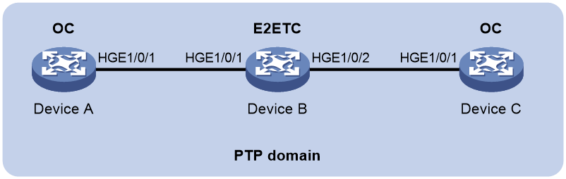
As shown in Figure 1, a PTP domain contains Device A, Device B, and Device C. Configure Layer 2 IEEE 1588v2 PTP as follows for time synchronization:
· Specify the IEEE 1588v2 PTP profile for the devices.
· Specify the OC clock node type for Device A and Device C, and E2ETC clock node type for Device B. These clock nodes elect a GM through BMC based on their respective default GM attributes.
Applicable hardware and software versions
The following matrix shows the hardware and software versions to which this configuration example is applicable:
|
Hardware |
Software version |
|
S6805 switch series |
Release 6607, Release 6616, Release 6616P01, Release 6635 and later |
|
S6825 switch series |
Release 6616, Release 6616P01, Release 6635 and later |
|
S6850 switch series S9850 switch series |
Release 6555P01, Release 6607, Release 6616, Release 6616P01, Release 6635 and later |
|
S9820-64H |
Release 6555P01, Release 6607, Release 6616, Release 6616P01, Release 6635 and later |
|
S9820-8C |
Release 6607, Release 6616, Release 6616P01, Release 6635 and later |
Procedures
|
|
IMPORTANT: · In Release 655x and Release 6607, for PTP to run on an interface, you only need to enable PTP on the interface. · In Release 6616, Release 6616P01, and Release 6635 and later, for PTP to run on an interface, you must enable PTP globally and on the interface. |
Configuring Device A
# Specify the IEEE 1588v2 PTP profile.
<DeviceA> system-view
[DeviceA] ptp profile 1588v2
# Specify the OC clock node type.
[DeviceA] ptp mode oc
# Specify a PTP domain.
[DeviceA] ptp domain 0
# Enable PTP globally.
[DeviceA] ptp global enable
# Specify PTP for obtaining the time.
[DeviceA] clock protocol ptp
# Enable PTP on HundredGigE 1/0/1.
[DeviceA] interface HundredGigE 1/0/1
[DeviceA-HundredGigE1/0/1] ptp enable
[DeviceA-HundredGigE1/0/1] quit
Configuring Device B
# Specify the IEEE 1588v2 PTP profile.
<DeviceB> system-view
[DeviceB] ptp profile 1588v2
# Specify the E2ETC clock node type.
[DeviceB] ptp mode e2etc
# Specify a PTP domain.
[DeviceB] ptp domain 0
# Enable PTP globally.
[DeviceB] ptp global enable
# Specify PTP for obtaining the time.
[DeviceB] clock protocol ptp
# Enable PTP on HundredGigE 1/0/1.
[DeviceB] interface HundredGigE 1/0/1
[DeviceB-HundredGigE1/0/1] ptp enable
[DeviceB-HundredGigE1/0/1] quit
# Enable PTP on HundredGigE 1/0/2.
[DeviceB] interface HundredGigE 1/0/2
[DeviceB-HundredGigE1/0/2] ptp enable
[DeviceB-HundredGigE1/0/2] quit
Configuring Device C
# Specify the IEEE 1588v2 PTP profile.
<DeviceC> system-view
[DeviceC] ptp profile 1588v2
# Specify the OC clock node type.
[DeviceC] ptp mode oc
# Specify a PTP domain.
[DeviceC] ptp domain 0
# Enable PTP globally.
[DeviceC] ptp global enable
# Specify PTP for obtaining the time.
[DeviceC] clock protocol ptp
# Enable PTP on HundredGigE 1/0/1.
[DeviceC] interface HundredGigE 1/0/1
[DeviceC-HundredGigE1/0/1] ptp enable
[DeviceC-HundredGigE1/0/1] quit
Verifying the configuration
|
|
IMPORTANT: Only in Release 6616, Release 6616P01, and Release 6635 and later, the device supports PTP multiple instances and the InstID field is displayed in the output of the display ptp interface brief command. |
When the network topology is stable, perform the following tasks to verify the PTP configuration:
· Use the display ptp clock command to display PTP clock information.
· Use the display ptp interface brief command to display brief PTP information.
# Display PTP clock information on Device A.
[DeviceA] display ptp clock
PTP global state : Enabled
PTP profile : IEEE 1588 Version 2
PTP mode : OC
Slave only : No
Clock ID : 000FE2-FFFE-FF0000
Clock type : Local
Clock domain : 0
Number of PTP ports : 1
Priority1 : 128
Priority2 : 128
Clock quality :
Class : 248
Accuracy : 254
Offset (log variance) : 65535
Offset from master : 0 (ns)
Mean path delay : 0 (ns)
Steps removed : 0
Local clock time : Sun Jan 15 20:57:29 2019
# Display brief PTP information on Device A.
[DeviceA] display ptp interface brief
Name InstID State Delay mechanism Clock step Asymmetry correction
HGE1/0/1 0 Master E2E Two 0
# Display PTP clock information on Device B.
[DeviceB] display ptp clock
PTP global state : Enabled
PTP profile : IEEE 1588 Version 2
PTP mode : E2ETC
Slave only : No
Clock ID : 000FE2-FFFE-FF0001
Clock type : Local
Clock domain : 0
Number of PTP ports : 2
Priority1 : 128
Priority2 : 128
Clock quality :
Class : 248
Accuracy : 254
Offset (log variance) : 65535
Offset from master : N/A
Mean path delay : N/A
Steps removed : N/A
Local clock time : Sun Jan 15 20:57:29 2019
# Display brief PTP information on Device B.
[DeviceB] display ptp interface brief
Name InstID State Delay mechanism Clock step Asymmetry correction
HGE1/0/1 0 N/A E2E Two 0
HGE1/0/2 0 N/A E2E Two 0
# Display PTP clock information on Device C.
[DeviceC] display ptp clock
PTP global state : Enabled
PTP profile : IEEE 1588 Version 2
PTP mode : OC
Slave only : No
Clock ID : 000FE2-FFFE-FF0002
Clock type : Local
Clock domain : 0
Number of PTP ports : 1
Priority1 : 128
Priority2 : 128
Clock quality :
Class : 248
Accuracy : 254
Offset (log variance) : 65535
Offset from master : 0 (ns)
Mean path delay : 0 (ns)
Steps removed : 0
Local clock time : Sun Jan 15 20:57:29 2019
# Display brief PTP information on Device C.
[DeviceC] display ptp interface brief
Name InstID State Delay mechanism Clock step Asymmetry correction
HGE1/0/1 0 Slave E2E Two 0
The command outputs show that Device A is elected as the GM and HundredGigE 1/0/1 on Device A is the master port.
Configuration files
· Device A and Device C:
#
clock protocol ptp
#
ptp profile 1588v2
ptp mode oc
#
interface HundredGigE 1/0/1
ptp enable
#
· Device B:
#
clock protocol ptp
#
ptp profile 1588v2
ptp mode e2etc
#
interface HundredGigE 1/0/1
ptp enable
#
interface HundredGigE 1/0/2
ptp enable
#
Example: Configuring Layer 3 IEEE 1588v2 PTP in multicast mode
Network configuration
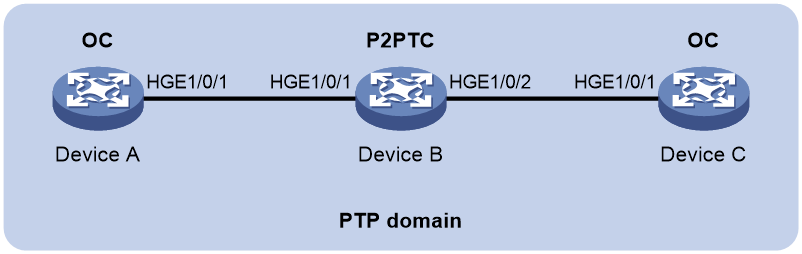
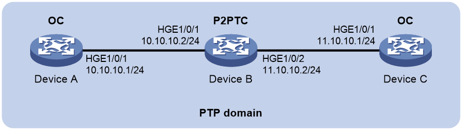
As shown in Figure 2, a PTP domain contains Device A, Device B, and Device C. Configure Layer 3 IEEE 1588v2 PTP in multicast mode as follows for time synchronization:
· Specify the IEEE 1588v2 PTP profile for the devices.
· Specify the OC clock node type for Device A and Device C, and the P2PTC clock node type for Device B. These clock nodes elect a GM through BMC based on their respective default GM attributes.
· Configure the multicast PTP transport mode and UDP (IPv4) transport protocol for the devices.
· Configure the peer delay measurement mechanism (p2p) for Device A and Device C.

Applicable hardware and software versions
The following matrix shows the hardware and software versions to which this configuration example is applicable:
|
Hardware |
Software version |
|
S6805 switch series |
Release 6607, Release 6616, Release 6616P01, Release 6635 and later |
|
S6825 switch series |
Release 6616, Release 6616P01, Release 6635 and later |
|
S6850 switch series S9850 switch series |
Release 6555P01, Release 6607, Release 6616, Release 6616P01, Release 6635 and later |
|
S9820-64H |
Release 6555P01, Release 6607, Release 6616, Release 6616P01, Release 6635 and later |
|
S9820-8C |
Release 6607, Release 6616, Release 6616P01, Release 6635 and later |
Procedures
|
|
IMPORTANT: · In Release 655x and Release 6607, for PTP to run on an interface, you only need to enable PTP on the interface. · In Release 6616, Release 6616P01, and Release 6635 and later, for PTP to run on an interface, you must enable PTP globally and on the interface. |
Configuring Device A
# Specify the IEEE 1588v2 PTP profile.
<DeviceA> system-view
[DeviceA] ptp profile 1588v2
# Specify the OC clock node type.
[DeviceA] ptp mode oc
# Specify a PTP domain.
[DeviceA] ptp domain 0
# Enable PTP globally.
[DeviceA] ptp global enable
# Configure the source IP address for multicast PTP transport.
[DeviceA] ptp source 10.10.10.1
# Specify PTP for obtaining the time.
[DeviceA] clock protocol ptp
# On HundredGigE 1/0/1, specify the UDP (IPv4) transport protocol and the peer delay measurement mechanism (p2p) and enable PTP.
[DeviceA] interface HundredGigE 1/0/1
[DeviceA-HundredGigE1/0/1] ptp transport-protocol udp
[DeviceA-HundredGigE1/0/1] ptp delay-mechanism p2p
[DeviceA-HundredGigE1/0/1] ptp enable
[DeviceA-HundredGigE1/0/1] quit
Configuring Device B
# Specify the IEEE 1588v2 PTP profile.
<DeviceB> system-view
[DeviceB] ptp profile 1588v2
# Specify the P2PTC clock node type.
[DeviceB] ptp mode p2ptc
# Specify a PTP domain.
[DeviceB] ptp domain 0
# Enable PTP globally.
[DeviceB] ptp global enable
# Configure the source IP address for multicast PTP transport.
[DeviceB] ptp source 10.10.10.2
# Specify PTP for obtaining the time.
[DeviceB] clock protocol ptp
# On HundredGigE 1/0/1, specify the UDP (IPv4) transport protocol and enable PTP.
[DeviceB] interface HundredGigE 1/0/1
[DeviceB-HundredGigE1/0/1] ptp transport-protocol udp
[DeviceB-HundredGigE1/0/1] ptp enable
[DeviceB-HundredGigE1/0/1] quit
# On HundredGigE 1/0/2, specify the UDP transport protocol and enable PTP.
[DeviceB] interface HundredGigE 1/0/2
[DeviceB-HundredGigE1/0/2] ptp transport-protocol udp
[DeviceB-HundredGigE1/0/2] ptp enable
[DeviceB-HundredGigE1/0/2] quit
Configuring Device C
# Specify the IEEE 1588v2 PTP profile.
<DeviceC> system-view
[DeviceC] ptp profile 1588v2
# Specify the OC clock node type.
[DeviceC] ptp mode oc
# Specify a PTP domain.
[DeviceC] ptp domain 0
# Enable PTP globally.
[DeviceC] ptp global enable
# Configure the source IP address for multicast PTP transport.
[DeviceC] ptp source 11.10.10.1
# Specify PTP for obtaining the time.
[DeviceC] clock protocol ptp
# On HundredGigE 1/0/1, specify the UDP (IPv4) transport protocol and the peer delay measurement mechanism (p2p) and enable PTP.
[DeviceC] interface HundredGigE 1/0/1
[DeviceC-HundredGigE1/0/1] ptp transport-protocol udp
[DeviceC-HundredGigE1/0/1] ptp delay-mechanism p2p
[DeviceC-HundredGigE1/0/1] ptp enable
[DeviceC-HundredGigE1/0/1] quit
Verifying the configuration
|
|
IMPORTANT: Only in Release 6616, Release 6616P01, and Release 6635 and later, the device supports PTP multiple instances and the InstID field is displayed in the output of the display ptp interface brief command. |
When the network topology is stable, perform the following tasks to verify the PTP configuration:
· Use the display ptp clock command to display PTP clock information.
· Use the display ptp interface brief command to display brief PTP information.
# Display PTP clock information on Device A.
[DeviceA] display ptp clock
PTP global state : Enabled
PTP profile : IEEE 1588 Version 2
PTP mode : OC
Slave only : No
Clock ID : 000FE2-FFFE-FF0000
Clock type : Local
Clock domain : 0
Number of PTP ports : 1
Priority1 : 128
Priority2 : 128
Clock quality :
Class : 248
Accuracy : 254
Offset (log variance) : 65535
Offset from master : 0 (ns)
Mean path delay : 0 (ns)
Steps removed : 0
Local clock time : Sun Jan 15 20:57:29 2019
# Display brief PTP information on Device A.
[DeviceA] display ptp interface brief
Name InstID State Delay mechanism Clock step Asymmetry correction
HGE1/0/1 0 Master P2P Two 0
# Display PTP clock information on Device B.
[DeviceB] display ptp clock
PTP global state : Enabled
PTP profile : IEEE 1588 Version 2
PTP mode : P2PTC
Slave only : No
Clock ID : 000FE2-FFFE-FF0001
Clock type : Local
Clock domain : 0
Number of PTP ports : 2
Priority1 : 128
Priority2 : 128
Clock quality :
Class : 248
Accuracy : 254
Offset (log variance) : 65535
Offset from master : N/A
Mean path delay : N/A
Steps removed : N/A
Local clock time : Sun Jan 15 20:57:29 2019
# Display brief PTP information on Device B.
[DeviceB] display ptp interface brief
Name InstID State Delay mechanism Clock step Asymmetry correction
HGE1/0/1 0 N/A P2P Two 0
HGE1/0/2 0 N/A P2P Two 0
# Display PTP clock information on Device C.
[DeviceC] display ptp clock
PTP global state : Enabled
PTP profile : IEEE 1588 Version 2
PTP mode : OC
Slave only : No
Clock ID : 000FE2-FFFE-FF0002
Clock type : Local
Clock domain : 0
Number of PTP ports : 1
Priority1 : 128
Priority2 : 128
Clock quality :
Class : 248
Accuracy : 254
Offset (log variance) : 65535
Offset from master : 0 (ns)
Mean path delay : 0 (ns)
Steps removed : 0
Local clock time : Sun Jan 15 20:57:29 2019
# Display brief PTP information on Device C.
[DeviceC] display ptp interface brief
Name InstID State Delay mechanism Clock step Asymmetry correction
HGE1/0/1 0 Slave P2P Two 0
The command outputs show that Device A is elected as the GM and HundredGigE 1/0/1 on Device A is the master port.
Configuration files
· Device A
#
clock protocol ptp
#
ptp profile 1588v2
ptp mode oc
ptp source 10.10.10.1
#
interface HundredGigE 1/0/1
ptp delay-mechanism p2p
ptp transport-protocol udp
ptp enable
#
· Device B
#
clock protocol ptp
#
ptp profile 1588v2
ptp mode p2ptc
ptp source 10.10.10.2
#
interface HundredGigE 1/0/1
ptp transport-protocol udp
ptp enable
#
interface HundredGigE 1/0/2
ptp transport-protocol udp
ptp enable
#
· Device C
#
clock protocol ptp
#
ptp profile 1588v2
ptp mode oc
ptp source 11.10.10.1
#
interface HundredGigE 1/0/1
ptp delay-mechanism p2p
ptp transport-protocol udp
ptp enable
#
Example: Configuring PTP (IEEE 1588 version 2, IPv4 UDP transport, unicast transmission)
Network configuration
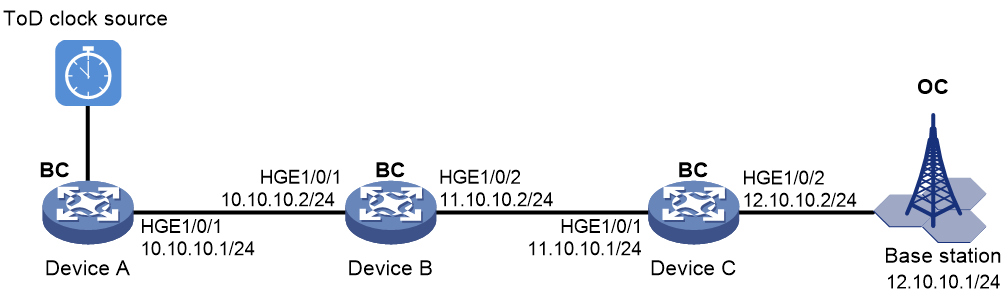
As shown in Figure 3, configure PTP (IEEE 1588 version 2, IPv4 UDP transport, unicast transmission) to enable Device A, Device B, Device C, and the base station to synchronize the time with the ToD clock source.
· Specify the IEEE 1588 version 2 PTP profile and unicast IPv4 UDP transport of PTP messages for Device A, Device B, and Device C.
· Assign Device A, Device B, Device C, and the base station to PTP domain 0. Specify the BC clock node type for Device A, Device B, and Device C.
· Connect Device A to the ToD clock source and Device C to the base station.
· Use the default Request_Response delay measurement mechanism on all clock nodes in the PTP domain.

Applicable hardware and software versions
The following matrix shows the hardware and software versions to which this configuration example is applicable:
|
Hardware |
Software version |
|
S6805 switch series |
Release 6607, Release 6616, Release 6616P01, Release 6635 and later |
|
S6825 switch series |
Release 6616, Release 6616P01, Release 6635 and later |
|
S6850 switch series S9850 switch series |
Release 6555P01, Release 6607, Release 6616, Release 6616P01, Release 6635 and later |
|
S9820-64H |
Release 6555P01, Release 6607, Release 6616, Release 6616P01, Release 6635 and later |
|
S9820-8C |
Release 6607, Release 6616, Release 6616P01, Release 6635 and later |
Restrictions and guidelines
The switch does not provide a ToD interface. You cannot use it as Device A, but can use it as Device B or C.
Procedures
|
|
IMPORTANT: · In Release 655x and Release 6607, for PTP to run on an interface, you only need to enable PTP on the interface. · In Release 6616, Release 6616P01, and Release 6635 and later, for PTP to run on an interface, you must enable PTP globally and on the interface. |
Assign IP addresses to the interfaces, and make sure the devices can reach each other, as shown in Figure 3. (Details not shown.)
Configure Device A
# Specify the IEEE 1588 version 2 PTP profile.
<DeviceA> system-view
[DeviceA] ptp profile 1588v2
# Specify the BC clock node type.
[DeviceA] ptp mode bc
# Create a PTP domain.
[DeviceA] ptp domain 0
# Specify PTP for obtaining the time.
[DeviceA] clock protocol ptp
# Enable PTP globally.
[DeviceA] ptp global enable
# Configure the delay time correction as 1000 nanoseconds for receiving ToD 0 clock signals.
[DeviceA] ptp tod0 input delay 1000
# Set priority 1 to 0 for the ToD 0 clock.
[DeviceA] ptp priority clock-source tod0 priority1 0
# On HundredGigE 1/0/1, configure the destination IP address for unicast PTP messages transmitted over IPv4 UDP, and enable PTP.
[DeviceA] interface hundredgige 1/0/1
[DeviceA-HundredGigE1/0/1] ptp transport-protocol udp
[DeviceA-HundredGigE1/0/1] ptp unicast-destination 10.10.10.2
[DeviceA-HundredGigE1/0/1] ptp enable
[DeviceA-HundredGigE1/0/1] quit
Configure Device B
# Specify the IEEE 1588 version 2 PTP profile.
<DeviceB> system-view
[DeviceB] ptp profile 1588v2
# Specify the BC clock node type.
[DeviceB] ptp mode bc
# Create a PTP domain.
[DeviceB] ptp domain 0
# Enable PTP globally.
[DeviceB] ptp global enable
# Specify PTP for obtaining the time.
[DeviceB] clock protocol ptp
# On HundredGigE 1/0/1, configure the destination IP address for unicast PTP messages transmitted over IPv4 UDP, and enable PTP.
[DeviceB] interface hundredgige 1/0/1
[DeviceB-HundredGigE1/0/1] ptp transport-protocol udp
[DeviceB-HundredGigE1/0/1] ptp unicast-destination 10.10.10.1
[DeviceB-HundredGigE1/0/1] ptp enable
[DeviceB-HundredGigE1/0/1] quit
# On HundredGigE 1/0/2, configure the destination IP address for unicast PTP messages transmitted over IPv4 UDP, and enable PTP.
[DeviceB] interface hundredgige 1/0/2
[DeviceB-HundredGigE1/0/2] ptp transport-protocol udp
[DeviceB-HundredGigE1/0/2] ptp unicast-destination 11.10.10.1
[DeviceB-HundredGigE1/0/2] ptp enable
[DeviceB-HundredGigE1/0/2] quit
Configure Device C
# Specify the IEEE 1588 version 2 PTP profile.
<DeviceC> system-view
[DeviceC] ptp profile 1588v2
# Specify the BC clock node type.
[DeviceC] ptp mode bc
# Create a PTP domain.
[DeviceC] ptp domain 0
# Enable PTP globally.
[DeviceC] ptp global enable
# Specify PTP for obtaining the time.
[DeviceC] clock protocol ptp
# On HundredGigE 1/0/1, configure the destination IP address for unicast PTP messages transmitted over IPv4 UDP, and enable PTP.
[DeviceC] interface hundredgige 1/0/1
[DeviceC-HundredGigE1/0/1] ptp transport-protocol udp
[DeviceC-HundredGigE1/0/1] ptp unicast-destination 11.10.10.2
[DeviceC-HundredGigE1/0/1] ptp enable
[DeviceC-HundredGigE1/0/1] quit
# On HundredGigE1/0/2, specify IPv4 UDP transport of PTP messages, configure the destination IP address for unicast PTP messages, and enable PTP.
[DeviceC] interface hundredgige 1/0/2
[DeviceC-HundredGigE1/0/2] ptp transport-protocol udp
[DeviceC-HundredGigE1/0/2] ptp unicast-destination 12.10.10.1
[DeviceC-HundredGigE1/0/2] ptp enable
[DeviceC-HundredGigE1/0/2] quit
Configure the base station
# Specify PTP domain 0.
# Specify IPv4 UDP transport of PTP messages.
# Set the destination IP address of unicast PTP messages to 12.10.10.2.
# Specify the Request_Response delay measurement mechanism.
For more information, see the configuration guide for the base station.
Verifying the configuration
|
|
IMPORTANT: Only in Release 6616, Release 6616P01, and Release 6635 and later, the device supports PTP multiple instances and the InstID field is displayed in the output of the display ptp interface brief command. |
When the network is stable, perform the following tasks:
· Use the display ptp clock command to display PTP clock information.
· Use the display ptp interface brief command to display brief PTP running information for all PTP interfaces.
# Display PTP clock information on Device A.
[DeviceA] display ptp clock
PTP global state : Enabled
PTP profile : IEEE 1588 Version 2
PTP mode : BC
Slave only : No
Lock status : Locked
Clock ID : 000FE2-FFFE-FF0000
Clock type : ToD0
ToD direction : In
ToD delay time : 1000 (ns)
Clock domain : 0
Number of PTP ports : 1
Priority1 : 0
Priority2 : 128
Clock quality :
Class : 6
Accuracy : 32
Offset (log variance) : 65535
Offset from master : 0 (ns)
Mean path delay : 0 (ns)
Steps removed : 0
Local clock time : Sun Jan 15 20:57:29 2019
# Display brief PTP running information for all PTP interfaces on Device A.
[DeviceA] display ptp interface brief
Name InstID State Delay mechanism Clock step Asymmetry correction
HGE1/0/1 0 Master E2E Two 0
# Display PTP clock information on Device C.
[DeviceC] display ptp clock
PTP global state : Enabled
PTP profile : IEEE 1588 Version 2
PTP mode : BC
Slave only : No
Lock status : Locked
Clock ID : 000FE2-FFFE-FF0001
Clock type : Local
Clock domain : 0
Number of PTP ports : 2
Priority1 : 128
Priority2 : 128
Clock quality :
Class : 248
Accuracy : 254
Offset (log variance) : 65535
Offset from master : 106368539000 (ns)
Mean path delay : 2791000 (ns)
Steps removed : 2
Local clock time : Sun Jan 15 20:57:29 2019
# Display brief PTP running information for all PTP interfaces on Device C.
[DeviceC] display ptp interface brief
Name InstID State Delay mechanism Clock step Asymmetry correction
HGE1/0/1 0 N/A E2E Two 0
HGE1/0/2 0 N/A E2E Two 0
Configuration files
· Device A
#
ptp profile 1588v2
ptp mode bc
ptp domain 0
clock protocol ptp
ptp global enable
ptp tod0 input delay 1000
ptp priority clock-source tod0 priority1 0
#
interface HundredGigE 1/0/1
ptp transport-protocol udp
ptp unicast-destination 10.10.10.2
ptp enable
#
· Device B
#
clock protocol ptp
#
ptp profile 1588v2
ptp mode e2etc
ptp domain 0
clock protocol ptp
ptp global enable
#
interface HundredGigE 1/0/1
ptp transport-protocol udp
ptp unicast-destination 10.10.10.1
ptp enable
#
interface HundredGigE 1/0/2
ptp transport-protocol udp
ptp unicast-destination 11.10.10.1
ptp enable
#
· Device C
#
clock protocol ptp
#
ptp profile 1588v2
ptp mode oc
ptp domain 0
clock protocol ptp
ptp global enable
#
interface HundredGigE 1/0/1
ptp transport-protocol udp
ptp unicast-destination 11.10.10.2
ptp enable
#
Example: Configuring IEEE 802.1AS PTP
Network configuration
As shown in Figure 4, a PTP domain contains Device A, Device B, and Device C. Configure IEEE 802.1AS PTP as follows for time synchronization:
· Specify the IEEE 802.1AS PTP profile for the devices.
· Specify the OC clock node type for Device A and Device C, and the P2PTC clock node type for Device B. These clock nodes elect a GM through BMC based on their respective default GM attributes.
Applicable hardware and software versions
The following matrix shows the hardware and software versions to which this configuration example is applicable:
|
Hardware |
Software version |
|
S6805 switch series |
Release 6607, Release 6616, Release 6616P01, Release 6635 and later |
|
S6825 switch series |
Release 6616, Release 6616P01, Release 6635 and later |
|
S6850 switch series S9850 switch series |
Release 6555P01, Release 6607, Release 6616, Release 6616P01, Release 6635 and later |
|
S9820-64H |
Release 6555P01, Release 6607, Release 6616, Release 6616P01, Release 6635 and later |
|
S9820-8C |
Release 6607, Release 6616, Release 6616P01, Release 6635 and later |
Procedures
|
|
IMPORTANT: · In Release 655x and Release 6607, for PTP to run on an interface, you only need to enable PTP on the interface. · In Release 6616, Release 6616P01, and Release 6635 and later, for PTP to run on an interface, you must enable PTP globally and on the interface. |
Configuring Device A
# Specify the IEEE 802.1AS PTP profile.
<DeviceA> system-view
[DeviceA] ptp profile 802.1AS
# Specify the OC clock node type.
[DeviceA] ptp mode oc
# Specify a PTP domain.
[DeviceA] ptp domain 0
# Enable PTP globally.
[DeviceA] ptp global enable
# Specify PTP for obtaining the time.
[DeviceA] clock protocol ptp
# Enable PTP on HundredGigE 1/0/1.
[DeviceA] interface HundredGigE 1/0/1
[DeviceA-HundredGigE1/0/1] ptp enable
[DeviceA-HundredGigE1/0/1] quit
Configuring Device B
# Specify the IEEE 802.1AS PTP profile.
<DeviceB> system-view
[DeviceB] ptp profile 802.1AS
# Specify the P2PTC clock node type.
[DeviceB] ptp mode p2ptc
# Specify a PTP domain.
[DeviceB] ptp domain 0
# Enable PTP globally.
[DeviceB] ptp global enable
# Specify PTP for obtaining the time.
[DeviceB] clock protocol ptp
# Enable PTP on HundredGigE 1/0/1.
[DeviceB] interface HundredGigE 1/0/1
[DeviceB-HundredGigE1/0/1] ptp enable
[DeviceB-HundredGigE1/0/1] quit
# Enable PTP on HundredGigE 1/0/2.
[DeviceB] interface HundredGigE 1/0/2
[DeviceB-HundredGigE1/0/2] ptp enable
[DeviceB-HundredGigE1/0/2] quit
Configuring Device C
# Specify the IEEE 1588 802.1AS PTP profile.
<DeviceC> system-view
[DeviceC] ptp profile 802.1AS
# Specify the OC clock node type.
[DeviceC] ptp mode oc
# Specify a PTP domain.
[DeviceC] ptp domain 0
# Enable PTP globally.
[DeviceC] ptp global enable
# Specify PTP for obtaining the time.
[DeviceC] clock protocol ptp
# Enable PTP on HundredGigE 1/0/1.
[DeviceC] interface HundredGigE 1/0/1
[DeviceC-HundredGigE1/0/1] ptp enable
[DeviceC-HundredGigE1/0/1] quit
Verifying the configuration
|
|
IMPORTANT: Only in Release 6616, Release 6616P01, and Release 6635 and later, the device supports PTP multiple instances and the InstID field is displayed in the output of the display ptp interface brief command. |
When the network topology is stable, perform the following tasks to verify the PTP configuration:
· Use the display ptp clock command to display PTP clock information.
· Use the display ptp interface brief command to display brief PTP information.
# Display PTP clock information on Device A.
[DeviceA] display ptp clock
PTP global state : Enabled
PTP profile : IEEE 802.1AS
PTP mode : OC
Slave only : No
Clock ID : 000FE2-FFFE-FF0000
Clock type : Local
Clock domain : 0
Number of PTP ports : 1
Priority1 : 246
Priority2 : 248
Clock quality :
Class : 248
Accuracy : 254
Offset (log variance) : 16640
Offset from master : 0 (ns)
Mean path delay : 0 (ns)
Steps removed : 0
Local clock time : Sun Jan 15 20:57:29 2019
# Display brief PTP information on Device A.
[DeviceA] display ptp interface brief
Name InstID State Delay mechanism Clock step Asymmetry correction
HGE1/0/1 0 Master P2P Two 0
# Display PTP clock information on Device B.
[DeviceB] display ptp clock
PTP global state : Enabled
PTP profile : IEEE 802.1AS
PTP mode : P2PTC
Slave only : No
Clock ID : 000FE2-FFFE-FF0001
Clock type : Local
Clock domain : 0
Number of PTP ports : 2
Priority1 : 246
Priority2 : 248
Clock quality :
Class : 248
Accuracy : 254
Offset (log variance) : 16640
Offset from master : N/A
Mean path delay : N/A
Steps removed : N/A
Local clock time : Sun Jan 15 20:57:29 2019
# Display brief PTP information on Device B.
[DeviceB] display ptp interface brief
Name InstID State Delay mechanism Clock step Asymmetry correction
HGE1/0/1 0 N/A P2P Two 0
HGE1/0/2 0 N/A P2P Two 0
# Display PTP clock information on Device C.
[DeviceC] display ptp clock
PTP global state : Enabled
PTP profile : IEEE 802.1AS
PTP mode : OC
Slave only : No
Clock ID : 000FE2-FFFE-FF0002
Clock type : Local
Clock domain : 0
Number of PTP ports : 1
Priority1 : 128
Priority2 : 128
Clock quality :
Class : 248
Accuracy : 254
Offset (log variance) : 65535
Offset from master : 0 (ns)
Mean path delay : 0 (ns)
Steps removed : 0
Local clock time : Sun Jan 15 20:57:29 2019
# Display brief PTP information on Device C.
[DeviceC] display ptp interface brief
Name InstID State Delay mechanism Clock step Asymmetry correction
HGE1/0/1 0 Slave P2P Two 0
The command outputs show that Device A is elected as the GM and HundredGigE 1/0/1 on Device A is the master port.
Configuration files
· Device A and Device C:
#
clock protocol ptp
#
ptp profile 8021as
ptp mode oc
#
interface HundredGigE 1/0/1
ptp enable
#
· Device B:
#
clock protocol ptp
#
ptp profile 8021as
ptp mode p2ptc
#
interface HundredGigE 1/0/1
ptp enable
#
interface HundredGigE 1/0/2
ptp enable
#
Example: Configuring SMPTE ST 2059-2 PTP in multicast mode
Network configuration
As shown in Figure 5, Device A, Device B, and Device C are in a PTP domain. Configure SMPTE ST 2059-2 PTP in multicast mode as follows for time synchronization:
· Specify the SMPTE ST 2059-2 PTP profile for the devices.
· Configure the multicast PTP transport mode for the devices.
· Specify the OC clock node type for Device A and Device C, and the P2PTC clock node type for Device B. All clock nodes elect a GM through BMC based on their respective default GM attributes.
· Configure the peer delay measurement mechanism (p2p) for Device A and Device C.
Applicable hardware and software versions
The following matrix shows the hardware and software versions to which this configuration example is applicable:
|
Hardware |
Software version |
|
S6805 switch series |
Release 6607, Release 6616, Release 6616P01, Release 6635 and later |
|
S6825 switch series |
Release 6616, Release 6616P01, Release 6635 and later |
|
S6850 switch series S9850 switch series |
Release 6555P01, Release 6607, Release 6616, Release 6616P01, Release 6635 and later |
|
S9820-64H |
Release 6555P01, Release 6607, Release 6616, Release 6616P01, Release 6635 and later |
|
S9820-8C |
Release 6607, Release 6616, Release 6616P01, Release 6635 and later |
Procedures
|
|
IMPORTANT: · In Release 655x and Release 6607, for PTP to run on an interface, you only need to enable PTP on the interface. · In Release 6616, Release 6616P01, and Release 6635 and later, for PTP to run on an interface, you must enable PTP globally and on the interface. |
Configuring Device A
# Specify the SMPTE ST 2059-2 PTP profile.
<DeviceA> system-view
[DeviceA] ptp profile st2059-2
# Specify the OC clock node type.
[DeviceA] ptp mode oc
# Specify a PTP domain.
[DeviceA] ptp domain 0
# Enable PTP globally.
[DeviceA] ptp global enable
# Configure the source IP address for multicast PTP transport.
[DeviceA] ptp source 10.10.10.1
# Specify PTP for obtaining the time.
[DeviceA] clock protocol ptp
# On HundredGigE 1/0/1, specify the peer delay measurement mechanism (p2p) and enable PTP.
[DeviceA] interface HundredGigE 1/0/1
[DeviceA-HundredGigE1/0/1] ptp delay-mechanism p2p
[DeviceA-HundredGigE1/0/1] ptp enable
[DeviceA-HundredGigE1/0/1] quit
Configuring Device B
# Specify the SMPTE ST 2059-2 PTP profile.
<DeviceB> system-view
[DeviceB] ptp profile st2059-2
# Specify the P2PTC clock node type.
[DeviceB] ptp mode p2ptc
# Specify a PTP domain.
[DeviceB] ptp domain 0
# Enable PTP globally.
[DeviceB] ptp global enable
# Configure the source IP address for multicast PTP transport.
[DeviceB] ptp source 10.10.10.2
# Specify PTP for obtaining the time.
[DeviceB] clock protocol ptp
# Enable PTP on HundredGigE 1/0/1.
[DeviceB] interface HundredGigE 1/0/1
[DeviceB-HundredGigE1/0/1] ptp enable
[DeviceB-HundredGigE1/0/1] quit
# Enable PTP on HundredGigE 1/0/2.
[DeviceB] interface HundredGigE 1/0/2
[DeviceB-HundredGigE1/0/2] ptp enable
[DeviceB-HundredGigE1/0/2] quit
Configuring Device C
# Specify the SMPTE ST 2059-2 PTP profile.
<DeviceC> system-view
[DeviceC] ptp profile st2059-2
# Specify the OC clock node type.
[DeviceC] ptp mode oc
# Specify a PTP domain.
[DeviceC] ptp domain 0
# Enable PTP globally.
[DeviceC] ptp global enable
# Configure the source IP address for multicast PTP transport.
[DeviceC] ptp source 11.10.10.
# Specify PTP for obtaining the time.
[DeviceC] clock protocol ptp
# On HundredGigE 1/0/1, specify the peer delay measurement mechanism (p2p) and enable PTP.
[DeviceC] interface HundredGigE 1/0/1
[DeviceC-HundredGigE1/0/1] ptp delay-mechanism p2p
[DeviceC-HundredGigE1/0/1] ptp enable
[DeviceC-HundredGigE1/0/1] quit
Verifying the configuration
|
|
IMPORTANT: Only in Release 6616, Release 6616P01, and Release 6635 and later, the device supports PTP multiple instances and the InstID field is displayed in the output of the display ptp interface brief command. |
When the network topology is stable, perform the following tasks to verify the PTP configuration:
· Use the display ptp clock command to display PTP clock information.
· Use the display ptp interface brief command to display brief PTP information.
# Display PTP clock information on Device A.
[DeviceA] display ptp clock
PTP global state : Enabled
PTP profile : SMPTE ST 2059-2
PTP mode : OC
Slave only : No
Clock ID : 000FE2-FFFE-FF0000
Clock type : Local
Clock domain : 0
Number of PTP ports : 1
Priority1 : 128
Priority2 : 128
Clock quality :
Class : 248
Accuracy : 254
Offset (log variance) : 65535
Offset from master : 0 (ns)
Mean path delay : 0 (ns)
Steps removed : 0
Local clock time : Sun Jan 15 20:57:29 2019
# Display brief PTP information on Device A.
[DeviceA] display ptp interface brief
Name InstID State Delay mechanism Clock step Asymmetry correction
HGE1/0/1 0 Master P2P Two 0
# Display PTP clock information on Device B.
[DeviceB] display ptp clock
PTP global state : Enabled
PTP profile : SMPTE ST 2059-2
PTP mode : P2PTC
Slave only : No
Clock ID : 000FE2-FFFE-FF0001
Clock type : Local
Clock domain : 0
Number of PTP ports : 2
Priority1 : 128
Priority2 : 128
Clock quality :
Class : 248
Accuracy : 254
Offset (log variance) : 65535
Offset from master : N/A
Mean path delay : N/A
Steps removed : N/A
Local clock time : Sun Jan 15 20:57:29 2019
# Display brief PTP information on Device B.
[DeviceB] display ptp interface brief
Name InstID State Delay mechanism Clock step Asymmetry correction
HGE1/0/1 0 N/A P2P Two 0
HGE1/0/2 0 N/A P2P Two 0
# Display PTP clock information on Device C.
[DeviceC] display ptp clock
PTP global state : Enabled
PTP profile : SMPTE ST 2059-2
PTP mode : OC
Slave only : No
Clock ID : 000FE2-FFFE-FF0002
Clock type : Local
Clock domain : 0
Number of PTP ports : 1
Priority1 : 128
Priority2 : 128
Clock quality :
Class : 248
Accuracy : 254
Offset (log variance) : 65535
Offset from master : 0 (ns)
Mean path delay : 0 (ns)
Steps removed : 0
Local clock time : Sun Jan 15 20:57:29 2019
# Display brief PTP information on Device C.
[DeviceC] display ptp interface brief
Name InstID State Delay mechanism Clock step Asymmetry correction
HGE1/0/1 0 Slave P2P Two 0
The output shows that Device A is elected as the GM and HundredGigE 1/0/1 on Device A is the master port.
Configuration files
· Device A:
#
clock protocol ptp
#
ptp profile st2059-2
ptp mode oc
ptp source 10.10.10.1
#
interface HundredGigE 1/0/1
ptp delay-mechanism p2p
ptp enable
#
· Device B:
#
clock protocol ptp
#
ptp profile st2059-2
ptp mode p2ptc
ptp source 10.10.10.2
#
interface HundredGigE 1/0/1
ptp enable
#
interface HundredGigE 1/0/2
ptp enable
#
· Device C:
#
clock protocol ptp
#
ptp profile st2059-2
ptp mode oc
ptp source 11.10.10.1
#
interface HundredGigE 1/0/1
ptp delay-mechanism p2p
ptp enable
#
Example: Configuring PTP (SMPTE ST 2059-2, IPv4 UDP transport, unicast transmission)
Network configuration
As shown in Figure 6, configure PTP (SMPTE ST 2059-2, IPv4 UDP transport, unicast transmission) to enable Device A, Device B, Device C, and the base station to synchronize time with the ToD clock source.
· Specify the SMPTE ST 2059-2 PTP profile and unicast IPv4 UDP transport of PTP messages for Device A, Device B, and Device C.
· Assign Device A, Device B, Device C, and the base station to PTP domain 0. Specify the BC clock node type for Device A, Device B, and Device C.
· Connect Device A to the ToD clock source and Device C to the base station.
· Use the default Request_Response delay measurement mechanism on all clock nodes in the PTP domain.
Applicable hardware and software versions
The following matrix shows the hardware and software versions to which this configuration example is applicable:
|
Hardware |
Software version |
|
S6805 switch series |
Release 6607, Release 6616, Release 6616P01, Release 6635 and later |
|
S6825 switch series |
Release 6616, Release 6616P01, Release 6635 and later |
|
S6850 switch series S9850 switch series |
Release 6555P01, Release 6607, Release 6616, Release 6616P01, Release 6635 and later |
|
S9820-64H |
Release 6555P01, Release 6607, Release 6616, Release 6616P01, Release 6635 and later |
|
S9820-8C |
Release 6607, Release 6616, Release 6616P01, Release 6635 and later |
Restrictions and guidelines
The switch does not provide a ToD interface. You cannot use it as Device A, but can use it as Device B or C.
Procedure
|
|
IMPORTANT: The SMPTE ST 2059-2 PTP profile supports IPv4 UDP transport rather than IEEE 802.3/Ethernet transport of PTP messages. It supports both multicast and unicast transmission of PTP messages. |
|
|
IMPORTANT: · In Release 655x and Release 6607, for PTP to run on an interface, you only need to enable PTP on the interface. · In Release 6616, Release 6616P01, and Release 6635 and later, for PTP to run on an interface, you must enable PTP globally and on the interface. |
Assign IP addresses to the interfaces, and make sure the devices can reach each other, as shown in Figure 6. (Details not shown.)
Configuring Device A
# Specify the SMPTE ST 2059-2 PTP profile.
<DeviceA> system-view
[DeviceA] ptp profile st2059-2
# Specify the BC clock node type.
[DeviceA] ptp mode bc
# Create a PTP domain.
[DeviceA] ptp domain 0
# Specify PTP for obtaining the time.
[DeviceA] clock protocol ptp
# Enable PTP globally.
[DeviceA] ptp global enable
# Configure the device to receive ToD 0 clock signals and set the delay correction value to 1000 nanoseconds.
[DeviceA] ptp tod0 input delay 1000
# Set priority 1 to 0 for the ToD 0 clock.
[DeviceA] ptp priority clock-source tod0 priority1 0
# On HundredGigE 1/0/1, configure the destination IP address for unicast PTP messages and enable PTP. (The SMPTE ST 2059-2 PTP profile transports PTP messages over IPv4 UDP by default.)
[DeviceA] interface hundredgige 1/0/1
[DeviceA-HundredGigE1/0/1] ptp transport-protocol udp
[DeviceA-HundredGigE1/0/1] ptp unicast-destination 10.10.10.2
[DeviceA-HundredGigE1/0/1] ptp enable
[DeviceA-HundredGigE1/0/1] quit
Configuring Device B
# Specify the SMPTE ST 2059-2 PTP profile.
<DeviceB> system-view
[DeviceB] ptp profile st2059-2
# Specify the BC clock node type.
[DeviceB] ptp mode e2etc
# Create a PTP domain.
[DeviceB] ptp domain 0
# Enable PTP globally.
[DeviceB] ptp global enable
# Specify PTP for obtaining the time.
[DeviceB] clock protocol ptp
# On HundredGigE 1/0/1, configure the destination IP address for unicast PTP messages and enable PTP. (The SMPTE ST 2059-2 PTP profile transports PTP messages over IPv4 UDP by default.)
[DeviceB] interface hundredgige 1/0/1
[DeviceB-HundredGigE1/0/1] ptp unicast-destination 10.10.10.1
[DeviceB-HundredGigE1/0/1] ptp enable
[DeviceB-HundredGigE1/0/1] quit
# On HundredGigE 1/0/2, configure the destination IP address for unicast PTP messages and enable PTP. (The SMPTE ST 2059-2 PTP profile transports PTP messages over IPv4 UDP by default.)
[DeviceB] interface hundredgige 1/0/2
[DeviceB-HundredGigE1/0/2] ptp unicast-destination 11.10.10.1
[DeviceB-HundredGigE1/0/2] ptp enable
[DeviceB-HundredGigE1/0/2] quit
Configuring Device C
# Specify the SMPTE ST 2059-2 PTP profile.
<DeviceC> system-view
[DeviceC] ptp profile st2059-2
# Specify the BC clock node type.
[DeviceC] ptp mode bc
# Create a PTP domain.
[DeviceC] ptp domain 0
# Enable PTP globally.
[DeviceC] ptp global enable
# Specify PTP for obtaining the time.
[DeviceC] clock protocol ptp
# On HundredGigE 1/0/1, configure the destination IP address for unicast PTP messages and enable PTP.
[DeviceC] interface hundredgige 1/0/1
[DeviceC-HundredGigE1/0/1] ptp transport-protocol udp
[DeviceC-HundredGigE1/0/1] ptp unicast-destination 11.10.10.2
[DeviceC-HundredGigE1/0/1] ptp enable
[DeviceC-HundredGigE1/0/1] quit
# On HundredGigE1/0/2, configure the destination IP address for unicast PTP messages and enable PTP. (The SMPTE ST 2059-2 PTP profile transports PTP messages over IPv4 UDP by default.)
[DeviceC] interface hundredgige 1/0/2
[DeviceC-HundredGigE1/0/2] ptp unicast-destination 12.10.10.1
[DeviceC-HundredGigE1/0/2] ptp enable
[DeviceC-HundredGigE1/0/2] quit
Configuring the base station.
# Specify PTP domain 0.
# Specify IPv4 UDP transport of PTP messages.
# Set the destination IP address of unicast PTP messages to 12.10.10.2.
# Specify the Request_Response delay measurement mechanism.
For more information, see the configuration guide for the base station.
Verifying the configuration
|
|
IMPORTANT: Only in Release 6616, Release 6616P01, and Release 6635 and later, the device supports PTP multiple instances and the InstID field is displayed in the output of the display ptp interface brief command. |
When the network is stable, perform the following tasks to verify the PTP configuration:
· Use the display ptp clock command to display PTP clock information.
· Use the display ptp interface brief command to display brief PTP running information.
# Display PTP clock information on Device A.
[DeviceA] display ptp clock
PTP global state : Enabled
PTP profile : SMPTE ST 2059-2
PTP mode : BC
Slave only : No
Lock status : Locked
Clock ID : 000FE2-FFFE-FF0000
Clock type : ToD0
ToD direction : In
ToD delay time : 1000 (ns)
Clock domain : 0
Number of PTP ports : 1
Priority1 : 0
Priority2 : 128
Clock quality :
Class : 6
Accuracy : 32
Offset (log variance) : 65535
Offset from master : 0 (ns)
Mean path delay : 0 (ns)
Steps removed : 0
Local clock time : Sun Jan 15 20:57:29 2019
# Display brief PTP running information on Device A.
[DeviceA] display ptp interface brief
Name InstID State Delay mechanism Clock step Asymmetry correction
HGE1/0/1 0 Master E2E Two 0
# Display PTP clock information on Device C.
[DeviceC] display ptp clock
PTP global state : Enabled
PTP profile : SMPTE ST 2059-2
PTP mode : BC
Slave only : No
Lock status : Locked
Clock ID : 000FE2-FFFE-FF0001
Clock type : Local
Clock domain : 0
Number of PTP ports : 2
Priority1 : 128
Priority2 : 128
Clock quality :
Class : 248
Accuracy : 254
Offset (log variance) : 65535
Offset from master : 106361246000 (ns)
Mean path delay : 2780000 (ns)
Steps removed : 2
Local clock time : Sun Jan 15 20:57:29 2019
# Display brief PTP running information on Device C.
[DeviceC] display ptp interface brief
Name InstID State Delay mechanism Clock step Asymmetry correction
HGE1/0/1 0 Slave E2E Two 0
HGE1/0/2 0 Master E2E Two 0
Configuration files
· Device A:
#
ptp profile st2059-2
ptp mode oc
ptp domain 0
clock protocol ptp
ptp global enable
ptp tod0 input delay 1000
ptp priority clock-source tod0 priority1 0
#
interface HundredGigE 1/0/1
ptp unicast-destination 10.10.10.2
ptp enable
#
· Device B
#
clock protocol ptp
#
ptp profile st2059-2
ptp mode e2etc
ptp domain 0
clock protocol ptp
ptp global enable
#
interface HundredGigE 1/0/1
ptp unicast-destination 10.10.10.1
ptp enable
#
interface HundredGigE 1/0/2
ptp unicast-destination 11.10.10.1
ptp enable
#
· Device C
#
clock protocol ptp
ptp profile st2059-2
ptp mode oc
ptp domain 0
clock protocol ptp
ptp global enable
#
interface HundredGigE 1/0/1
ptp unicast-destination 11.10.10.2
ptp enable
#
Related documentation
Use this document in conjunction with the following documents for the product and software version you are working with:
· Network Management and Monitoring Configuration Guide
· Network Management and Monitoring Command Reference
