- Table of Contents
-
- H3C Fixed Port Campus Switches Configuration Examples-6W103
- 00-Applicable hardware and software versions
- 01-Login Management Configuration Examples
- 02-RBAC Configuration Examples
- 03-Software Upgrade Examples
- 04-ISSU Configuration Examples
- 05-Software Patching Examples
- 06-Ethernet Link Aggregation Configuration Examples
- 07-Port Isolation Configuration Examples
- 08-Spanning Tree Configuration Examples
- 09-VLAN Configuration Examples
- 10-VLAN Tagging Configuration Examples
- 11-DHCP Snooping Configuration Examples
- 12-Cross-Subnet Dynamic IP Address Allocation Configuration Examples
- 13-IPv6 over IPv4 Tunneling with OSPFv3 Configuration Examples
- 14-IPv6 over IPv4 GRE Tunnel Configuration Examples
- 15-GRE with OSPF Configuration Examples
- 16-OSPF Configuration Examples
- 17-IS-IS Configuration Examples
- 18-BGP Configuration Examples
- 19-Policy-Based Routing Configuration Examples
- 20-OSPFv3 Configuration Examples
- 21-IPv6 IS-IS Configuration Examples
- 22-Routing Policy Configuration Examples
- 23-IGMP Snooping Configuration Examples
- 24-IGMP Configuration Examples
- 25-MLD Snooping Configuration Examples
- 26-IPv6 Multicast VLAN Configuration Examples
- 27-ACL Configuration Examples
- 28-Traffic Policing Configuration Examples
- 29-GTS and Rate Limiting Configuration Examples
- 30-Traffic Filtering Configuration Examples
- 31-AAA Configuration Examples
- 32-Port Security Configuration Examples
- 33-Portal Configuration Examples
- 34-SSH Configuration Examples
- 35-IP Source Guard Configuration Examples
- 36-Ethernet OAM Configuration Examples
- 37-CFD Configuration Examples
- 38-DLDP Configuration Examples
- 39-VRRP Configuration Examples
- 40-BFD Configuration Examples
- 41-NTP Configuration Examples
- 42-SNMP Configuration Examples
- 43-NQA Configuration Examples
- 44-Mirroring Configuration Examples
- 45-sFlow Configuration Examples
- 46-OpenFlow Configuration Examples
- 47-MAC Address Table Configuration Examples
- 48-Static Multicast MAC Address Entry Configuration Examples
- 49-IP Unnumbered Configuration Examples
- 50-MVRP Configuration Examples
- 51-MCE Configuration Examples
- 52-Attack Protection Configuration Examples
- 53-Smart Link Configuration Examples
- 54-RRPP Configuration Examples
- 55-BGP Route Selection Configuration Examples
- 56-IS-IS Route Summarization Configuration Examples
- 57-VXLAN Configuration Examples
- 58-DRNI Configuration Examples
- 59-IRF 3.1 Configuration Examples
- 60-PTP Configuration Examples
- 61-S-MLAG Configuration Examples
- 62-Puppet Configuration Examples
- 63-802.1X Configuration Examples
- 64-MAC Authentication Configuration Examples
- 65-ISATAP Tunnel and 6to4 Tunnel Configuration Examples
- 66-BIDIR-PIM Configuration Examples
- 67-Congestion Avoidance and Queue Scheduling Configuration Examples
- 68-Basic MPLS Configuration Examples
- 69-MPLS L3VPN Configuration Examples
- 70-MPLS OAM Configuration Examples
- 71-EVPN-DCI over an MPLS L3VPN Network Configuration Examples
- 72-DRNI and EVPN Configuration Examples
- 73-Multicast VPN Configuration Examples
- 74-MPLS TE Configuration Examples
- 75-Control Plane-Based QoS Policy Configuration Examples
- 76-Priority Mapping and Queue Scheduling Configuration Examples
- 77-ARP Attack Protection Configuration Examples
- 78-IRF Software Upgrade Configuration Examples
- 79-IRF Member Replacement Configuration Examples
- 80-Layer 3 Multicast on Multicast Source-Side DR System Configuration Examples
- 81-EVPN Multicast Configuration Examples
- Related Documents
-
| Title | Size | Download |
|---|---|---|
| 78-IRF Software Upgrade Configuration Examples | 145.46 KB |
Contents
Example: Upgrading software on an IRF fabric
Applicable hardware and software versions
Checking the environment after IRF software upgrade
Introduction
This document provides examples for upgrading software on an IRF fabric.
Prerequisites
The configuration examples in this document were created and verified in a lab environment, and all the devices were started with the factory default configuration. When you are working on a live network, make sure you understand the potential impact of every command on your network.
This document assumes that you have basic knowledge of IRF.
Example: Upgrading software on an IRF fabric
Network configuration
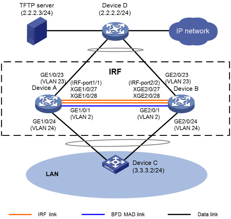
As shown in Figure 1, Device A and Device B have set up an IRF fabric. Device A is the master device and its member ID is 1, and Device B is the standby device and its member ID is 2. BFD MAD is used for multi-active collision detection.
The current software version of the IRF fabric is R2432p06. Upgrade the software version to R2720. After software upgrade, Device A is still the master device.
Analysis
H3C devices support upgrade methods as shown in Table 1. In this example, software is upgraded from the CLI by using the boot loader method. To reduce service interruption time during the upgrade process, IRF split and IRF merge will be performed during the upgrade process.
Table 1 Software upgrade methods
|
Upgrade method |
Software types |
Remarks |
|
Upgrading from the CLI by using the boot loader method |
· BootWare image · Comware images (excluding incremental patches) |
This method is disruptive. You must reboot the entire device to complete the upgrade. All models support this method. |
|
Performing an ISSU from the CLI |
Comware images |
This method enables a software upgrade with a minimum amount of downtime. Some models support this method. |
|
Upgrading from the BootWare menu |
· BootWare image · Comware images |
Use this method when the device cannot start up correctly. To use this method, first connect to the console port and power cycle the device. Then, press Ctrl+B at prompt to access the BootWare menu. For more information about upgrading software from the BootWare menu, see the release notes for the software version. All models support this method. |
To upgrade software on an IRF fabric from the CLI by using the boot loader method:
1. Shut down all uplink and downlink service interfaces on the master device (Device A) in bulk to switch traffic from Device A to Device B. To enter interface range view, use the interface range command.
2. Upgrade software on Device A from the CLI by using the boot loader method and reboot the device. During the reboot, shut down IRF physical interfaces Ten-GigabitEthernet 2/0/27 and Ten-GigabitEthernet 2/0/28 on Device B. The IRF fabric splits.
|
|
CAUTION: To prevent configuration loss from affecting interface status and causing IRF merge failure or service traffic interruption, do not save the running configuration on any IRF member device when the IRF fabric splits. |
|
|
NOTE: To split an IRF fabric, you can remove cables from IRF physical interfaces or shut down all IRF physical interfaces on the standby device. The latter method is simpler. In this example, the latter method is used. |
3. Shut down all uplink and downlink service interfaces on the standby device (Device B) in bulk. Bring up all uplink and downlink service interfaces on Device A to switch service traffic back to Device A.
4. Upgrade software on Device B. After Device B reboots, Device A and Device B automatically form an IRF fabric.
Applicable hardware and software versions
The following matrix shows the hardware and software versions to which this configuration example is applicable:
|
Hardware |
Software version |
|
S6812 switch series S6813 switch series |
Release 66xx |
|
S6550XE-HI switch series |
Release 6008 and later |
|
S6525XE-HI switch series |
Release 6008 and later |
|
S5850 switch series |
Release 8005 and later |
|
S5570S-EI switch series |
Release 11xx |
|
S5560X-EI switch series |
Release 63xx, Release 65xx, Release 66xx |
|
S5560X-HI switch series |
Release 63xx, Release 65xx, Release 66xx |
|
S5500V2-EI switch series |
Release 63xx, Release 65xx, Release 66xx |
|
MS4520V2-30F switch |
Release 63xx, Release 65xx, Release 66xx |
|
MS4520V2-30C switch MS4520V2-54C switch |
Release 65xx, Release 66xx |
|
MS4520V2-28S switch MS4520V2-24TP switch |
Release 63xx |
|
S6520X-HI switch series S6520X-EI switch series |
Release 63xx, Release 65xx, Release 66xx |
|
S6520X-SI switch series S6520-SI switch series |
Release 63xx, Release 65xx, Release 66xx |
|
S5000-EI switch series |
Release 63xx, Release 65xx, Release 66xx |
|
MS4600 switch series |
Release 63xx, Release 65xx, Release 66xx |
|
ES5500 switch series |
Release 63xx, Release 65xx, Release 66xx |
|
S5560S-EI switch series S5560S-SI switch series |
Release 63xx |
|
S5500V3-24P-SI switch S5500V3-48P-SI switch |
Release 63xx |
|
S5500V3-SI switch series (except the S5500V3-24P-SI and S5500V3-48P-SI switches) |
Release 11xx |
|
S5170-EI switch series |
Release 11xx |
|
S5130S-HI switch series S5130S-EI switch series S5130S-SI switch series S5130S-LI switch series |
Release 63xx |
|
S5120V2-SI switch series S5120V2-LI switch series |
Release 63xx |
|
S5120V3-EI switch series |
Release 11xx |
|
S5120V3-36F-SI switch S5120V3-28P-HPWR-SI switch S5120V3-54P-PWR-SI switch |
Release 11xx |
|
S5120V3-SI switch series (except the S5120V3-36F-SI, S5120V3-28P-HPWR-SI, and S5120V3-54P-PWR-SI switches) |
Release 63xx |
|
S5120V3-LI switch series |
Release 63xx |
|
S3600V3-EI switch series |
Release 11xx |
|
S3600V3-SI switch series |
Release 11xx |
|
S3100V3-EI switch series S3100V3-SI switch series |
Release 63xx |
|
S5110V2 switch series |
Release 63xx |
|
S5110V2-SI switch series |
Release 63xx |
|
S5000V3-EI switch series S5000V5-EI switch series |
Release 63xx |
|
S5000E-X switch series S5000X-EI switch series |
Release 63xx |
|
E128C switch E152C switch E500C switch series E500D switch series |
Release 63xx |
|
MS4320V2 switch series MS4320V3 switch series MS4300V2 switch series MS4320 switch series MS4200 switch series |
Release 63xx |
|
WS5850-WiNet switch series |
Release 63xx |
|
WS5820-WiNet switch series WS5810-WiNet switch series |
Release 63xx |
|
WAS6000 switch series |
Release 63xx |
|
IE4300-12P-AC switch IE4300-12P-PWR switch IE4300-M switch series IE4320 switch series |
Release 63xx |
Restrictions and guidelines
Whole upgrade process
As a best practice to discover, locate, and analyze issues in time, record all operations during the whole upgrade process.
Before IRF software upgrade
· Make sure all member devices and cards are in stable state. For this purpose, execute the display system stable state command and verify that the value for the State field is Stable. If a member device or card is not in stable state, identify the reason. Do not upgrade software on the IRF fabric unless all member devices and cards are in stable state.
· Prepare scripts in advance for shutting down and bringing up uplink and downlink service interfaces. To prevent omission of service interfaces from resulting in exceptions in the upgrade process, make sure the scripts contain all service interfaces on the IRF fabric.
During IRF software upgrade
· First upgrade software for the master device. Make sure the master device has a higher member priority than the standby device.
· To avoid configuration loss, do not save the running configuration on any IRF member device when the IRF fabric splits.
· After the master device starts up after software upgrade, make sure all member devices and cards are running correctly. Use the display interface command to verify that all interfaces are displayed, and then wait for 2 minutes before you move to the next step.
· After the standby device reboots, reconnect IRF links before the standby device finishes restartup. If you reconnect IRF links after the standby device finishes restartup, the standby device must reboot again to complete IRF merge with the master device.
After IRF software upgrade
· Make sure all member devices and cards are in stable state. For this purpose, execute the display system stable state command and verify that the value for the State field is Stable.
· Verify that all services on the IRF fabric are running correctly. If a service cannot run correctly, locate and resolve the issue as soon as possible.
Prerequisites
1. Configure NSR settings on the IRF fabric:
During the upgrade process, master/standby switchover will occur. If the IRF fabric runs routing protocols, for example, BGP and OSPF, the switchover issue might cause routing neighbor flapping and affect packet forwarding. For high availability, configure NSR for routing protocols. Before upgrading software on the IRF fabric, configure NSR settings and save the configuration. In this example, OSPF NSR and BGP NSR are configured for illustration.
# Enable NSR for OSPF process 100.
<IRF> system-view
[IRF] ospf 100
[IRF-ospf-100] non-stop-routing
[IRF-ospf-100] display ospf non-stop-routing status
OSPF Process 100 with Router ID 1.1.1.1
Non Stop Routing information
Non Stop Routing capability : Enabled
Upgrade phase : Normal
[IRF-ospf-100] quit
[IRF] quit
# Enable NSR for BGP process 100.
[IRF] bgp 100
[IRF-bgp-default] non-stop-routing
[IRF-bgp-default] display bgp non-stop-routing status
BGP NSR status: Ready
Location of preferred standby process: Slot 2
TCP NSR status: Ready
[IRF-bgp-default] quit
[IRF-bgp] quit
2. Verify that the master device is assigned a higher member priority than the standby device. The higher the priority value, the higher the priority to be the master device. In this example, set the member priority of Device A to 32.
[IRF] irf member 1 priority 32
3. Check single-armed service links.
IRF split will occur during the upgrade process. In addition, you need to shut down all service interfaces on one member device. For high availability, deploy physical links dual-homed to both member devices for each uplink device and downlink device. That is, connect Device D to both Device A and Device B, and connect Device C to both Device A and Device B. If single-armed services exist, service access exception will occur during the upgrade process. As a best practice, add backup links for single-armed services.
4. Check IRF status and collect information:
Before the upgrade process, you must check the device status, HA status, IRF status, and MAD status.
|
|
IMPORTANT: Make sure all member devices and cards are in stable state. If a member device or card is not in stable state, identify the reason. Do not upgrade software on an IRF fabric unless all member devices and cards are in stable state. |
# Display device information.
[IRF] display device
Slot Type State Subslot Soft Ver Patch Ver
1 S5560X-30C-PWR-EIMaster 0 2432p06 None
2 S5560X-30C-PWR-EIStandby 0 2432p06 None
# Display system stable status.
[IRF] display system stable state
System state : Stable
Redundancy state : Stable
Slot CPU Role State
1 0 Active Stable
2 0 Standby Stable
# Display brief information about system stability and status, including CPU running status, redundancy status, and NSR status.
[IRF] display system stable state summary
System state : Stable
Redundancy state : Stable
NSR state : Ready
# Display IRF information.
<IRF> display irf
MemberID Role Priority CPU-Mac Description
*+1 Master 32 f010-90db-7402 ---
2 Standby 1 f010-90db-0204 ---
--------------------------------------------------
* indicates the device is the master.
+ indicates the device through which the user logs in.
The bridge MAC of the IRF is: 0000-0001-0002
Auto upgrade : yes
Mac persistent : 12 min
Domain ID : 0
# Display IRF configuration on all IRF member devices.
<IRF> display irf configuration
MemberID NewID IRF-Port1 IRF-Port2
1 1 Ten-GigabitEthernet1/0/27 disable
Ten-GigabitEthernet1/0/28
2 2 disable Ten-GigabitEthernet2/0/27
Ten-GigabitEthernet2/0/28
# Display IRF link information.
<IRF> display irf link
Member 1
IRF Port Interface Status
1 Ten-GigabitEthernet1/0/27 UP
Ten-GigabitEthernet1/0/28 UP
2 disable --
Member 2
IRF Port Interface Status
1 disable --
2 Ten-GigabitEthernet2/0/27 UP
Ten-GigabitEthernet2/0/28 UP
# Display IRF topology information.
<IRF> display irf topology
Topology Info
-------------------------------------------------------------------------
IRF-Port1 IRF-Port2
MemberID Link neighbor Link neighbor Belong To
2 DIS --- UP 1 f010-90db-7402
1 UP 2 DIS --- f010-90db-7402
# Display detailed MAD information.
<IRF> display mad verbose
Multi-active recovery state: No
Excluded ports (user-configured):
Excluded ports (system-configured):
IRF physical interfaces:
Ten-GigabitEthernet1/0/27
Ten-GigabitEthernet1/0/28
Ten-GigabitEthernet2/0/27
Ten-GigabitEthernet2/0/28
BFD MAD interfaces:
Vlan-interface2
MAD ARP disabled.
MAD ND disabled.
MAD LACP disabled.
MAD BFD enabled interface: Vlan-interface2
MAD status : Normal
Member ID MAD IP address Neighbor MAD status
1 192.168.2.1/24 2 Normal
2 192.168.2.2/24 1 Normal
# Display BFD session information.
[IRF] display bfd session
Total Sessions: 1 Up Sessions: 1 Init mode: Active
IPv4 session working in control packet mode:
LD/RD SourceAddr DestAddr State Holdtime Interface
32833/0 192.168.2.1 192.168.2.2 Down / Vlan2
5. Verify that the IRF fabric is running correctly, and collect status information, including status information for protocols, ports, and table entries, for comparing the information with the information collected after the upgrade:
# Display system version information.
<IRF> display version
H3C Comware Software, Version 7.1.070, Release 2432p06
Copyright (c) 2004-2021 New H3C Technologies Co., Ltd. All rights reserved.
H3C S5560X-30C-PWR-EI uptime is 4 weeks, 2 days, 22 hours, 3 minutes
Last reboot reason : User reboot
Boot image: flash:/cmw710-system-r2432p06.bin
Boot image version: 7.1.070, Release 2432p06
Compiled Sep 29 2021 11:00:00
System image: flash:/cmw710-system-r2432p06.bin
System image version: 7.1.070, Release 2432p06
Compiled Sep 29 2021 11:00:00
...
# Display the running configuration.
<IRF> display current-configuration
#
version 7.1.070, Release 2432p06
#
sysname IRF
#
irf mac-address persistent timer
irf auto-update enable
undo irf link-delay
irf member 1 priority 32
irf member 2 priority 1
#
ospf 100
non-stop-routing
#
...
# Display brief interface information.
<IRF> display interface brief
Brief information on interfaces in route mode:
Link: ADM - administratively down; Stby - standby
Protocol: (s) - spoofing
Interface Link Protocol Primary IP Description
InLoop0 UP UP(s) --
MGE0/0/0 DOWN DOWN --
NULL0 UP UP(s) --
REG0 UP -- --
Vlan2 UP UP 192.168.2.1
Brief information on interfaces in bridge mode:
Link: ADM - administratively down; Stby - standby
Speed: (a) - auto
Duplex: (a)/A - auto; H - half; F - full
Type: A - access; T - trunk; H - hybrid
Interface Link Speed Duplex Type PVID Description
GE1/0/1 UP 1G(a) F(a) A 2
GE1/0/2 DOWN auto A A 1
GE1/0/3 DOWN auto A A 1
...
# Display ARP entries.
<IRF> display arp
Type: S-Static D-Dynamic O-Openflow R-Rule M-Multiport I-Invalid
IP address MAC address VLAN/VSI name Interface Aging Type
2.2.2.2 6451-c3f1-0302 20 BAGG1 941 D
3.3.3.2 6451-ccf3-0402 30 BAGG2 1020 D
# Display MAC address table information.
<IRF> display mac-address
MAC Address VLAN ID State Port/Nickname Aging
a442-f6d0-9344 2 Learned GE1/0/1 Y
6451-c3f1-0302 23 Learned BAGG1 Y
6451-ccf3-0402 24 Learned BAGG2 Y
# Display information about OSPF neighbors. In this example, static routing is used. The command does not display any information.
<IRF> display ospf peer
# Display routing table information.
<IRF> display ip routing-table
Destinations : 21 Routes : 21
Destination/Mask Proto Pre Cost NextHop Interface
0.0.0.0/32 Direct 60 0 2.2.2.2 Vlan23
1.1.1.1/32 Direct 0 0 127.0.0.1 InLoop0
2.2.2.0/24 Direct 0 0 2.2.2.1 Vlan23
2.2.2.0/32 Direct 0 0 2.2.2.1 Vlan23
2.2.2.1/32 Direct 0 0 127.0.0.1 InLoop0
2.2.2.255/32 Direct 0 0 2.2.2.1 Vlan23
3.3.3.0/24 Direct 0 0 3.3.3.1 Vlan24
3.3.3.0/32 Direct 0 0 3.3.3.1 Vlan24
3.3.3.1/32 Direct 0 0 127.0.0.1 InLoop0
3.3.3.255/32 Direct 0 0 3.3.3.1 Vlan24
127.0.0.0/8 Direct 0 0 127.0.0.1 InLoop0
127.0.0.0/32 Direct 0 0 127.0.0.1 InLoop0
127.0.0.1/32 Direct 0 0 127.0.0.1 InLoop0
127.255.255.255/32 Direct 0 0 127.0.0.1 InLoop0
192.168.2.0/24 Direct 0 0 192.168.2.1 Vlan2
192.168.2.0/32 Direct 0 0 192.168.2.1 Vlan2
192.168.2.1/32 Direct 0 0 127.0.0.1 InLoop0
192.168.2.255/32 Direct 0 0 192.168.2.1 Vlan2
224.0.0.0/4 Direct 0 0 0.0.0.0 NULL0
224.0.0.0/24 Direct 0 0 0.0.0.0 NULL0
255.255.255.255/32 Direct 0 0 127.0.0.1 InLoop0
# Display detailed information about aggregation groups.
<IRF> display link-aggregation verbose
Loadsharing Type: Shar -- Loadsharing, NonS -- Non-Loadsharing
Port Status: S -- Selected, U -- Unselected, I -- Individual
Port: A -- Auto port, M -- Management port, R -- Reference port
Flags: A -- LACP_Activity, B -- LACP_Timeout, C -- Aggregation,
D -- Synchronization, E -- Collecting, F -- Distributing,
G -- Defaulted, H -- Expired
Aggregate Interface: Bridge-Aggregation1
Aggregation Mode: Static
Loadsharing Type: Shar
Management VLANs: None
Port Status Priority Oper-Key
GE1/0/10(R) S 32768 1
GE2/0/10 S 32768 1
Aggregate Interface: Bridge-Aggregation2
Aggregation Mode: Static
Loadsharing Type: Shar
Management VLANs: None
Port Status Priority Oper-Key
GE1/0/23 S 32768 2
GE2/0/23(R) S 32768 2
6. Back up the main next-startup configuration file:
# Save the running configuration to the main next-startup configuration file.
<IRF> save
The current configuration will be written to the device. Are you sure? [Y/N]:y
Please input the file name(*.cfg)[flash:/startup.cfg]
(To leave the existing filename unchanged, press the enter key):
Validating file. Please wait...
The startup.cfg file already exists.
Compared with the startup.cfg file, The current configuration adds 0 commands and deletes 0 commands.
If you want to see the configuration differences, please cancel this operation, and then use the display diff command to show the details.
If you continue the save operation, the file will be overwritten.
Are you sure you want to continue the save operation? [Y/N]:y
Saving the current configuration to the file. Please wait...
Saved the current configuration to mainboard device successfully.
Slot 2:
Save next configuration file successfully.
# Display the names of the current startup configuration file and the next-startup configuration files.
<IRF> display startup
MainBoard:
Current startup saved-configuration file: NULL
Next main startup saved-configuration file: flash:/startup.cfg
Next backup startup saved-configuration file: NULL
Slot 2:
Current startup saved-configuration file: NULL
Next main startup saved-configuration file: flash:/startup.cfg
Next backup startup saved-configuration file: NULL
# Back up next-startup configuration file startup.cfg.
<IRF> tftp 2.2.2.3 put startup.cfg
Press CTRL+C to abort.
% Total % Received % Xferd Average Speed Time Time Time Current
Dload Upload Total Spent Left Speed
100 8128 0 0 100 8128 0 170k --:--:-- --:--:-- --:--:-- 233k
<IRF>
7. Verify that the member devices have sufficient storage space to store the new startup image file:
# On Device A, display information about files and directories in the current directory.
<IRF> dir
Directory of flash:
1 -rw- 220684 Nov 15 2021 17:37:48 defaultfile.zip
2 drw- - Jan 01 2021 00:01:33 diagfile
...
554288 KB total (228880 KB free)
# On Device B, display information about files and directories in the current directory.
<IRF> dir slot2#flash:/
Directory of flash:
1 -rw- 220684 Nov 15 2021 17:37:48 defaultfile.zip
2 drw- - Jan 01 2011 00:01:33 diagfile
...
554288 KB total (221104 KB free)
8. Upload the new startup image file and validate the file:
# Upload image file r2702.ipe to Device A, and verify that the size of the uploaded file on Device A is the same as that of the officially released one. If the file sizes are different, upload the file again.
<IRF> tftp 2.2.2.3 get r2702.ipe
Press CTRL+C to abort.
% Total % Received % Xferd Average Speed Time Time Time Current
Dload Upload Total Spent Left Speed
100 133M 100 133M 0 0 180k 0 0:12:33 0:12:33 --:--:-- 177k
Writing file...Done.
<IRF> dir r2702.ipe
Directory of flash:
25 -rw- 139699200 Nov 19 2021 12:07:56 r2702.ipe
524288 KB total (167504 KB free)
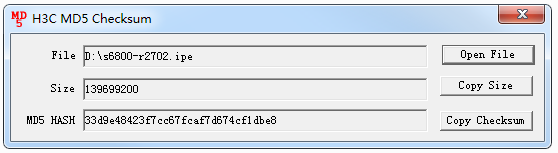
# Use MD5 digest to validate the new startup image file. The file is valid if the digest calculated by using the md5sum command is the same as the MD5 digest published when the image file was released or the same as the file's digest generated by using an MD5 tool.
<IRF> md5sum r2702.ipe
MD5 digest:
33d9e48423f7cc67fcaf7d674cf1dbe8
Figure 2 Using an MD5 tool to generate a digest
9. Copy the new startup image file to Device B for backup.
<IRF> copy r2702.ipe slot2#flash:/
Copy flash:/r2702.ipe to slot2#flash:/r2702.ipe? [Y/N]:y
Copying file flash:/r2702.ipe to slot2#flash:/r2702.ipe.................. Done.
Procedures
Specifying the new startup image file and verifying the configuration
# Specifying file r2702.ipe as the main startup image file.
<IRF> boot-loader file flash:/r2702.ipe all main
Verifying the file flash:/r2702.ipe on slot 1...................................
..................Done.
H3C S5560X-30C-PWR-EI images in IPE:
cmw710-boot-r2702.bin
cmw710-system-r2702.bin
This command will set the main startup software images. Continue? [Y/N]:y
Add images to slot 1.
Decompressing file cmw710-boot-r2702.bin to flash:/cmw710-boot-r2702.bin...........................Done.
Decompressing file cmw710-system-r2702.bin to flash:/cmw710-system-r2702.bin.......................................................................................................................................................................Done.
Verifying the file flash:/cmw710-boot-r2702.bin on slot 1........Done.
Verifying the file flash:/cmw710-system-r2702.bin on slot 1................................................Done.
The images that have passed all examinations will be used as the main startup software images at the next reboot on slot 1.
Loading............................................................Done.
Loading....................................................................................................................................................................................................................................................Done.
Verifying the file flash:/cmw710-boot-r2702.bin on slot 2....Done.
Verifying the file flash:/cmw710-system-r2702.bin on slot 2...................Done.
The images that have passed all examinations will be used as the main startup software images at the next reboot on slot 2.
Decompression completed.
Do you want to delete flash:/5560.ipe now? [Y/N]:n
# Verify that file r2702.ipe has been specified as the main startup image file on all slots.
<IRF> display boot-loader
Software images on slot 1:
Current software images:
flash:/cmw710-boot-r2432p06.bin
flash:/cmw710-system-r2432p06.bin
Main startup software images:
flash:/cmw710-boot-r2702.bin
flash:/cmw710-system-r2702.bin
Backup startup software images:
flash:/cmw710-boot-r2432p06.bin
flash:/cmw710-system-r2432p06.bin
Software images on slot 2:
Current software images:
flash:cmw710-boot-r2432p06.bin
flash:/cmw710-system-r2432p06.bin
Main startup software images:
flash:/cmw710-boot-r2702.bin
flash:/cmw710-system-r2702.bin
Backup startup software images:
flash:/cmw710-boot-r2432p06.bin
flash:/cmw710-system-r2432p06.bin
Disabling MAD (BFD MAD in the example)
# Disable MAD and remove cables from the interfaces used for MAD. In this example, VLAN-interface 2 is used for BFD MAD.
<IRF> system-view
[IRF] interface vlan-interface 2
[IRF-Vlan-interface2] undo mad bfd enable
[IRF-Vlan-interface2] display this
#
interface Vlan-interface2
#
return
Shutting down service interfaces on the master device and saving the configuration
# Shut down all uplink and downlink interfaces on Device A. Do not shut down IRF physical interfaces and the interfaces used for BFD MAD on Device A.
[IRF] interface range name yewu interface gigabitethernet 1/0/2 to gigabitethernet 1/0/22 ten-gigabitethernet 1/0/25 to ten-gigabitethernet 1/0/26
[IRF] interface range name yewu
[IRF-if-range-yewu] shutdown
[IRF-if-range-yewu] quit
[IRF] quit
# On Device D and Device C, ping each other. If the ping operations succeed, Device C and Device D are reachable. If the ping operations fail, locate and resolve the communication failure issue. (Details not shown.)
# Verify that all services have been switched from Device A to Device B. (Details not shown.)
# Save the running configuration.
<IRF> save
The current configuration will be written to the device. Are you sure? [Y/N]:y
Please input the file name(*.cfg)[flash:/startup.cfg]
(To leave the existing filename unchanged, press the enter key):
Validating file. Please wait...
The startup.cfg file already exists.
Compared with the startup.cfg file, The current configuration adds 0 commands and deletes 0 commands.
If you want to see the configuration differences, please cancel this operation, and then use the display diff command to show the details.
If you continue the save operation, the file will be overwritten.
Are you sure you want to continue the save operation? [Y/N]:y
Saving the current configuration to the file. Please wait...
Saved the current configuration to mainboard device successfully.
Slot 2:
Save next configuration file successfully.
Rebooting the master device and splitting the IRF fabric
# Reboot the master device (Device A).
<IRF> reboot slot 1
Start to check configuration with next startup configuration file, please wait..
.......DONE!
Current configuration may be lost after the reboot, save current configuration?
[Y/N]:y
Please input the file name(*.cfg)[flash:/startup.cfg]
(To leave the existing filename unchanged, press the enter key):
flash:/startup.cfg exists, overwrite? [Y/N]:y
Validating file. Please wait...
Saved the current configuration to mainboard device successfully.
This command will reboot the device. Continue? [Y/N]:y
Now rebooting, please wait..........
# Shut down IRF physical interfaces Ten-GigabitEthernet 2/0/27 and Ten-GigabitEthernet 2/0/28 on Device B to cause IRF split.
|
|
CAUTION: The IRF fabric splits after you shut down all IRF physical interfaces on Device B. To prevent configuration loss from affecting interface status and causing IRF merge failure or service traffic interruption, do not save the running configuration on the master device (Device A) when the IRF fabric splits. |
<IRF> system-view
[IRF] interface range name irf-port interface ten-gigabitethernet 2/0/27 to ten-gigabitethernet 2/0/28
[IRF-if-range-irf-port] shutdown
Shutting down service interfaces on the standby device and bringing up service interfaces on the master device
|
|
IMPORTANT: To reduce the service interruption time, shorten the operation time as much as possible. As a best practice, prepare the required command lines in advance and copy and paste the command lines to the devices. |
# After Device A finishes startup, verify that all interfaces are displayed.
<IRF> display interface
# Wait for about 2 minutes for forwarding entry convergence on Device A.
# Verify that Device A is stable.
<IRF> display system stable state
System state : Stable
Redundancy state : No redundancy
Slot CPU Role State
1 0 Active Stable
# Log in to Device B and shut down all service interfaces on the device. Do not shut down IRF physical interfaces and the interfaces used for BFD MAD.
<IRF> system-view
[IRF] interface range name yewu-2 interface gigabitethernet 2/0/2 to gigabitethernet 2/0/22 ten-gigabitethernet 2/0/25 to ten-gigabitethernet 2/0/26
[IRF] interface range name yewu-2
[IRF-if-range-yewu-2] shutdown
# Log in to Device A and bring up all service interfaces on the device.
<IRF> system-view
[IRF] interface range name yewu
[IRF-if-range-yewu] undo shutdown
Rebooting the standby device
# Verify that services have been switched back to Device A. (Details not shown.)
# ,Log in to Device B and reboot Device B.
<IRF> reboot slot 2
Start to check configuration with next startup configuration file, please wait..
.......DONE!
Current configuration may be lost after the reboot, save current configuration?
[Y/N]:y
Please input the file name(*.cfg)[flash:/startup.cfg]
(To leave the existing filename unchanged, press the enter key):
flash:/startup.cfg exists, overwrite? [Y/N]:y
Validating file. Please wait...
Saved the current configuration to mainboard device successfully.
This command will reboot the device. Continue? [Y/N]:y
Now rebooting, please wait..........
After Device B reboots, it acts as a standby device to complete IRF merge with Device A.
Checking the environment after IRF software upgrade
1. Check IRF status and services:
# After Device B reboots, check IRF status and service status, collect status information, and compare the status information with that before the upgrade process. If the status information is inconsistent before and after upgrade, locate and resolve the issue.
[IRF] display system stable state
[IRF] display irf
[IRF] display irf configuration
[IRF] display irf link
[IRF] display irf topology
2. Enable MAD and verify the configuration.
[IRF] interface vlan-interface 2
[IRF-Vlan-interface2] mad bfd enable
[IRF-Vlan-interface2] mad ip address 192.168.2.1 24 member 1
[IRF-Vlan-interface2] mad ip address 192.168.2.2 24 member 2
[IRF-Vlan-interface2] quit
[IRF] display mad verbose
Multi-active recovery state: No
Excluded ports (user-configured):
Excluded ports (system-configured):
IRF physical interfaces:
Ten-GigabitEthernet1/0/27
Ten-GigabitEthernet1/0/28
Ten-GigabitEthernet2/0/27
Ten-GigabitEthernet2/0/28
BFD MAD interfaces:
Vlan-interface2
MAD ARP disabled.
MAD ND disabled.
MAD LACP disabled.
MAD BFD enabled interface: Vlan-interface2
MAD status : Normal
Member ID MAD IP address Neighbor MAD status
1 192.168.2.1/24 2 Normal
2 192.168.2.2/24 1 Normal
3. Delete unused settings as needed and save the configuration.
[IRF] undo interface range yewu
[IRF] undo interface range yewu-2
[IRF] save
4. Check the device status, collect device status information, and compare the device status with that before the upgrade process. If the device status information is inconsistent before and after upgrade, locate and resolve the issue.
<IRF> display version
<IRF> display current-configuration
<IRF> display interface brief
<IRF> display arp
<IRF> display mac-address
<IRF> displayplay ospf peer
<IRF> display ip routing-table
<IRF> display link-aggregation verbose
Verifying the configuration
# Display IRF version information. Verify that the software version has been upgraded from R2432p06 to R2720.
<IRF> display version
H3C Comware Software, Version 7.1.070, Release 2720
Copyright (c) 2004-2021 New H3C Technologies Co., Ltd. All rights reserved.
H3C S5560X-30C-PWR-EI uptime is 4 weeks, 5 days, 14 hours, 32 minutes
Last reboot reason : User reboot
Boot image: flash:/cmw710-boot-r2720.bin
Boot image version: 7.1.070, Release 2720
Compiled Sep 29 2021 11:00:00
System image: flash:/cmw710-system-r2720.bin
System image version: 7.1.070, Release 2720
Compiled Sep 29 2021 11:00:00
Slot 1:
Uptime is 4 weeks,5 days,14 hours,32 minutes
S5560X-30C-PWR-EI with 1 RMI XLS408 Processor
BOARD TYPE: S5560X-30C-PWR-EI
DRAM: 2048M bytes
FLASH: 512M bytes
PCB 1 Version: VER.A
FPGA Version: NONE
Bootrom Version: 158
CPLD 1 Version: 002
CPLD 2 Version: 001
Release Version: H3C S5560X-30C-PWR-EI-2720
Patch Version: None
Reboot Cause: UserReboot
[SubSlot 0] 48XGT+6QSFP Plus
