- Table of Contents
-
- H3C Fixed Port Campus Switches Configuration Examples-6W103
- 00-Applicable hardware and software versions
- 01-Login Management Configuration Examples
- 02-RBAC Configuration Examples
- 03-Software Upgrade Examples
- 04-ISSU Configuration Examples
- 05-Software Patching Examples
- 06-Ethernet Link Aggregation Configuration Examples
- 07-Port Isolation Configuration Examples
- 08-Spanning Tree Configuration Examples
- 09-VLAN Configuration Examples
- 10-VLAN Tagging Configuration Examples
- 11-DHCP Snooping Configuration Examples
- 12-Cross-Subnet Dynamic IP Address Allocation Configuration Examples
- 13-IPv6 over IPv4 Tunneling with OSPFv3 Configuration Examples
- 14-IPv6 over IPv4 GRE Tunnel Configuration Examples
- 15-GRE with OSPF Configuration Examples
- 16-OSPF Configuration Examples
- 17-IS-IS Configuration Examples
- 18-BGP Configuration Examples
- 19-Policy-Based Routing Configuration Examples
- 20-OSPFv3 Configuration Examples
- 21-IPv6 IS-IS Configuration Examples
- 22-Routing Policy Configuration Examples
- 23-IGMP Snooping Configuration Examples
- 24-IGMP Configuration Examples
- 25-MLD Snooping Configuration Examples
- 26-IPv6 Multicast VLAN Configuration Examples
- 27-ACL Configuration Examples
- 28-Traffic Policing Configuration Examples
- 29-GTS and Rate Limiting Configuration Examples
- 30-Traffic Filtering Configuration Examples
- 31-AAA Configuration Examples
- 32-Port Security Configuration Examples
- 33-Portal Configuration Examples
- 34-SSH Configuration Examples
- 35-IP Source Guard Configuration Examples
- 36-Ethernet OAM Configuration Examples
- 37-CFD Configuration Examples
- 38-DLDP Configuration Examples
- 39-VRRP Configuration Examples
- 40-BFD Configuration Examples
- 41-NTP Configuration Examples
- 42-SNMP Configuration Examples
- 43-NQA Configuration Examples
- 44-Mirroring Configuration Examples
- 45-sFlow Configuration Examples
- 46-OpenFlow Configuration Examples
- 47-MAC Address Table Configuration Examples
- 48-Static Multicast MAC Address Entry Configuration Examples
- 49-IP Unnumbered Configuration Examples
- 50-MVRP Configuration Examples
- 51-MCE Configuration Examples
- 52-Attack Protection Configuration Examples
- 53-Smart Link Configuration Examples
- 54-RRPP Configuration Examples
- 55-BGP Route Selection Configuration Examples
- 56-IS-IS Route Summarization Configuration Examples
- 57-VXLAN Configuration Examples
- 58-DRNI Configuration Examples
- 59-IRF 3.1 Configuration Examples
- 60-PTP Configuration Examples
- 61-S-MLAG Configuration Examples
- 62-Puppet Configuration Examples
- 63-802.1X Configuration Examples
- 64-MAC Authentication Configuration Examples
- 65-ISATAP Tunnel and 6to4 Tunnel Configuration Examples
- 66-BIDIR-PIM Configuration Examples
- 67-Congestion Avoidance and Queue Scheduling Configuration Examples
- 68-Basic MPLS Configuration Examples
- 69-MPLS L3VPN Configuration Examples
- 70-MPLS OAM Configuration Examples
- 71-EVPN-DCI over an MPLS L3VPN Network Configuration Examples
- 72-DRNI and EVPN Configuration Examples
- 73-Multicast VPN Configuration Examples
- 74-MPLS TE Configuration Examples
- 75-Control Plane-Based QoS Policy Configuration Examples
- 76-Priority Mapping and Queue Scheduling Configuration Examples
- 77-ARP Attack Protection Configuration Examples
- 78-IRF Software Upgrade Configuration Examples
- 79-IRF Member Replacement Configuration Examples
- 80-Layer 3 Multicast on Multicast Source-Side DR System Configuration Examples
- 81-EVPN Multicast Configuration Examples
- Related Documents
-
| Title | Size | Download |
|---|---|---|
| 50-MVRP Configuration Examples | 139.14 KB |
Applicable hardware and software versions
Verifying local VLAN information on all devices
Verifying VLAN information after changing the registration mode
Verifying VLAN information after changing the network topology
Introduction
This document provides MVRP configuration examples.
Prerequisites
The configuration examples in this document were created and verified in a lab environment, and all the devices were started with the factory default configuration. When you are working on a live network, make sure you understand the potential impact of every command on your network.
This document assumes that you have basic knowledge of MVRP.
Example: Configuring MVRP
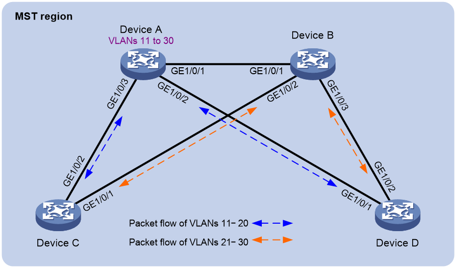
Network configuration
As shown in Figure 1:
· Device A and Device B are core layer devices. Device C and Device D are aggregation layer devices.
· Ports on all devices allow packets from VLANs 11 through 30 to pass through.
· MSTP implements load balancing and link backup for traffic of VLANs 11 through 30 between the core layer devices and the aggregation layer devices.
Configure MVRP on all devices to synchronize and update VLAN information. When the network is stable, set the registration mode to fixed on GigabitEthernet 1/0/1 of Device B to maintain dynamic VLAN information.
Analysis
To meet the network requirements, you must perform the following tasks:
· To assign all devices to the same MST region, configure the same settings for the following parameters on all the devices:
¡ Spanning tree mode. (This example uses the default mode MSTP.)
¡ MST region name. (This example uses the region name test.)
¡ MST region revision level. (This example uses the default setting 0.)
¡ VLAN-to-instance mappings. (This example maps VLANs 11 through 20 to MSTI 1, and maps VLANs 21 through 30 to MSTI 2.)
· For MSTIs 1 and 2 to use different uplinks for backup, set Device A and Device B as the root bridges of MSTIs 1 and 2, respectively.
· Make sure each MSTI is mapped to an existing VLAN on each device in the network.
Applicable hardware and software versions
The following matrix shows the hardware and software versions to which this configuration example is applicable:
|
Hardware |
Software version |
|
S6812 switch series S6813 switch series |
Release 66xx |
|
S6550XE-HI switch series |
Release 6008 and later |
|
S6525XE-HI switch series |
Release 6008 and later |
|
S5850 switch series |
Release 8005 and later |
|
S5570S-EI switch series |
Release 11xx |
|
S5560X-EI switch series |
Release 63xx, Release 65xx, Release 66xx |
|
S5560X-HI switch series |
Release 63xx, Release 65xx, Release 66xx |
|
S5500V2-EI switch series |
Release 63xx, Release 65xx, Release 66xx |
|
MS4520V2-30F switch |
Release 63xx, Release 65xx, Release 66xx |
|
MS4520V2-30C switch MS4520V2-54C switch |
Release 65xx, Release 66xx |
|
MS4520V2-28S switch MS4520V2-24TP switch |
Release 63xx |
|
S6520X-HI switch series S6520X-EI switch series |
Release 63xx, Release 65xx, Release 66xx |
|
S6520X-SI switch series S6520-SI switch series |
Release 63xx, Release 65xx, Release 66xx |
|
S5000-EI switch series |
Release 63xx, Release 65xx, Release 66xx |
|
MS4600 switch series |
Release 63xx, Release 65xx, Release 66xx |
|
ES5500 switch series |
Release 63xx, Release 65xx, Release 66xx |
|
S5560S-EI switch series S5560S-SI switch series |
Release 63xx |
|
S5500V3-24P-SI switch S5500V3-48P-SI switch |
Release 63xx |
|
S5500V3-SI switch series (except S5500V3-24P-SI switch and S5500V3-48P-SI switch) |
Release 11xx |
|
S5170-EI switch series |
Release 11xx |
|
S5130S-HI switch series S5130S-EI switch series S5130S-SI switch series S5130S-LI switch series |
Release 63xx |
|
S5120V2-SI switch series S5120V2-LI switch series |
Release 63xx |
|
S5120V3-EI switch series |
Release 11xx |
|
S5120V3-36F-SI switch S5120V3-28P-HPWR-SI switch S5120V3-54P-PWR-SI switch |
Release 11xx |
|
S5120V3-SI switch series (except S5120V3-36F-SI switch, S5120V3-28P-HPWR-SI switch, and S5120V3-54P-PWR-SI switch) |
Release 63xx |
|
S5120V3-LI switch series |
Release 63xx |
|
S3600V3-EI switch series |
Release 11xx |
|
S3600V3-SI switch series |
Release 11xx |
|
S3100V3-EI switch series S3100V3-SI switch series |
Release 63xx |
|
S5110V2 switch series |
Release 63xx |
|
S5110V2-SI switch series |
Release 63xx |
|
S5000V3-EI switch series S5000V5-EI switch series |
Release 63xx |
|
S5000E-X switch series S5000X-EI switch series |
Release 63xx |
|
E128C switch E152C switch E500C switch series E500D switch series |
Release 63xx |
|
MS4320V2 switch series MS4320V3 switch series MS4300V2 switch series MS4320 switch series MS4200 switch series |
Release 63xx |
|
WS5850-WiNet switch series |
Release 63xx |
|
WS5820-WiNet switch series WS5810-WiNet switch series |
Release 63xx |
|
WAS6000 switch series |
Release 63xx |
|
IE4300-12P-AC switch IE4300-12P-PWR switch IE4300-M switch series IE4320 switch series |
Release 63xx |
Restrictions and guidelines
When you configure MVRP, follow these restrictions and guidelines:
· MVRP can work with STP, RSTP, or MSTP. Ports blocked by STP, RSTP, or MSTP can receive and send MVRP frames. MVRP cannot work with other link layer topology protocols, including service loopback, PVST, RRPP, and Smart Link.
· On a Layer 2 aggregate interface, MVRP takes effect on both the aggregate interface and all Selected member ports in the link aggregation group.
· MVRP configuration made on an aggregation group member port takes effect only after the port is removed from the aggregation group.
Procedures
Configuring Device A
# Create VLANs 11 through 30.
<DeviceA> system-view
[DeviceA] vlan 11 to 30
# Enter MST region view.
[DeviceA] stp region-configuration
# Set the MST region name to test.
[DeviceA-mst-region] region-name test
# Map VLANs 11 through 20 to MSTI 1.
[DeviceA-mst-region] instance 1 vlan 11 to 20
# Map VLANs 21 through 30 to MSTI 2.
[DeviceA-mst-region] instance 2 vlan 21 to 30
# Activate the MST region configuration.
[DeviceA-mst-region] active region-configuration
[DeviceA-mst-region] quit
# Configure Device A as the root bridge of MSTI 1.
[DeviceA] stp instance 1 root primary
# Enable the spanning tree feature globally.
[DeviceA] stp global enable
# Configure the ports GigabitEthernet 1/0/1 through GigabitEthernet 1/0/3 as trunk ports, assign the ports to VLANs 11 through 30, and enable MVRP on these ports.
[DeviceA] interface range gigabitethernet 1/0/1 to gigabitethernet 1/0/3
[DeviceA-if-range] port link-mode bridge
[DeviceA-if-range] port link-type trunk
[DeviceA-if-range] port trunk permit vlan 11 to 30
[DeviceA-if-range] mvrp enable
[DeviceA-if-range] undo shutdown
[DeviceA-if-range] quit
Configuring Device B
# Create VLANs 11 and 21.
<DeviceB> system-view
[DeviceB] vlan 11
[DeviceB-vlan11] quit
[DeviceB] vlan 21
[DeviceB-vlan21] quit
# Enter MST region view.
[DeviceB] stp region-configuration
# Set the MST region name to test.
[DeviceB-mst-region] region-name test
# Map VLANs 11 through 20 to MSTI 1.
[DeviceB-mst-region] instance 1 vlan 11 to 20
# Map VLANs 21 through 30 to MSTI 2.
[DeviceB-mst-region] instance 2 vlan 21 to 30
# Activate the MST region configuration.
[DeviceB-mst-region] active region-configuration
[DeviceB-mst-region] quit
# Configure Device B as the root bridge of MSTI 2.
[DeviceB] stp instance 2 root primary
# Enable the spanning tree feature globally.
[DeviceB] stp global enable
# Enable MVRP globally.
[DeviceB] mvrp global enable
# Configure the ports GigabitEthernet 1/0/1 through GigabitEthernet 1/0/3 as trunk ports, assign the ports to VLANs 11 through 30, and enable MVRP on these ports.
[DeviceB] interface range gigabitethernet 1/0/1 to gigabitethernet 1/0/3
[DeviceB-if-range] port link-mode bridge
[DeviceB-if-range] port link-type trunk
[DeviceB-if-range] port trunk permit vlan 11 to 30
[DeviceB-if-range] mvrp enable
[DeviceB-if-range] undo shutdown
[DeviceB-if-range] quit
Configuring Device C
# Create VLANs 11 and 21.
<DeviceC> system-view
[DeviceC] vlan 11
[DeviceC-vlan11] quit
[DeviceC] vlan 21
[DeviceC-vlan21] quit
# Enter MST region view.
[DeviceC] stp region-configuration
# Set the MST region name to test.
[DeviceC-mst-region] region-name test
# Map VLANs 11 through 20 to MSTI 1.
[DeviceC-mst-region] instance 1 vlan 11 to 20
# Map VLANs 21 through 30 to MSTI 2.
[DeviceC-mst-region] instance 2 vlan 21 to 30
# Activate the MST region configuration.
[DeviceC-mst-region] active region-configuration
[DeviceC-mst-region] quit
# Enable the spanning tree feature globally.
[DeviceC] stp global enable
# Enable MVRP globally.
[DeviceC] mvrp global enable
# Configure the ports GigabitEthernet 1/0/1 and GigabitEthernet 1/0/2 as trunk ports, assign the ports to VLANs 11 through 30, and enable MVRP on these ports.
[DeviceC] interface range gigabitethernet 1/0/1 to gigabitethernet 1/0/2
[DeviceC-if-range] port link-mode bridge
[DeviceC-if-range] port link-type trunk
[DeviceC-if-range] port trunk permit vlan 11 to 30
[DeviceC-if-range] mvrp enable
[DeviceC-if-range] undo shutdown
[DeviceC-if-range] quit
Configuring Device D
Configure Device D in the same way Device C is configured. (Details not shown.)
Verifying the configuration
Verifying MSTI topologies
# Display brief spanning tree information on Device A.
[DeviceA] display stp brief
MST ID Port Role STP State Protection
...
1 GigabitEthernet1/0/1 DESI FORWARDING NONE
1 GigabitEthernet1/0/2 DESI FORWARDING NONE
1 GigabitEthernet1/0/3 DESI FORWARDING NONE
2 GigabitEthernet1/0/1 ROOT FORWARDING NONE
2 GigabitEthernet1/0/2 DESI FORWARDING NONE
2 GigabitEthernet1/0/3 DESI FORWARDING NONE
# Display brief spanning tree information on Device B.
[DeviceB] display stp brief
MST ID Port Role STP State Protection
...
1 GigabitEthernet1/0/1 ROOT FORWARDING NONE
1 GigabitEthernet1/0/2 DESI FORWARDING NONE
1 GigabitEthernet1/0/3 DESI FORWARDING NONE
2 GigabitEthernet1/0/1 DESI FORWARDING NONE
2 GigabitEthernet1/0/2 DESI FORWARDING NONE
2 GigabitEthernet1/0/3 DESI FORWARDING NONE
# Display brief spanning tree information on Device C.
[DeviceC] display stp brief
MST ID Port Role STP State Protection
...
1 GigabitEthernet1/0/1 ALTE DISCARDING NONE
1 GigabitEthernet1/0/2 ROOT FORWARDING NONE
2 GigabitEthernet1/0/1 ROOT FORWARDING NONE
2 GigabitEthernet1/0/2 ALTE DISCARDING NONE
# Display brief spanning tree information on Device D.
[DeviceD] display stp brief
MST ID Port Role STP State Protection
...
1 GigabitEthernet1/0/1 ROOT FORWARDING NONE
1 GigabitEthernet1/0/2 ALTE DISCARDING NONE
2 GigabitEthernet1/0/1 ALTE DISCARDING NONE
2 GigabitEthernet1/0/2 ROOT FORWARDING NONE
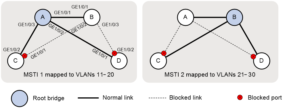
Based on the output, you can get MSTI topologies, as shown in Figure 2.
Verifying local VLAN information on all devices
# Display local VLAN information on Device A.
[DeviceA] display mvrp running-status
-------[MVRP Global Info] -------
Global Status : Enabled
Compliance-GVRP : False
----[GigabitEthernet1/0/1] ----
Config Status : Enabled
Running Status : Enabled
Join Timer : 20 (centiseconds)
Leave Timer : 60 (centiseconds)
Periodic Timer : 100 (centiseconds)
LeaveAll Timer : 1000 (centiseconds)
Registration Type : Normal
Registered VLANs :
1(default), 11, 21
Declared VLANs :
1(default), 11-30
Propagated VLANs :
1(default), 11, 21
----[GigabitEthernet1/0/2] ----
Config Status : Enabled
Running Status : Enabled
Join Timer : 20 (centiseconds)
Leave Timer : 60 (centiseconds)
Periodic Timer : 100 (centiseconds)
LeaveAll Timer : 1000 (centiseconds)
Registration Type : Normal
Registered VLANs :
1(default), 11
Declared VLANs :
1(default), 11-30
Propagated VLANs :
1(default), 11
----[GigabitEthernet1/0/3] ----
Config Status : Enabled
Running Status : Enabled
Join Timer : 20 (centiseconds)
Leave Timer : 60 (centiseconds)
Periodic Timer : 100 (centiseconds)
LeaveAll Timer : 1000 (centiseconds)
Registration Type : Normal
Registered VLANs :
1(default), 11
Declared VLANs :
1(default), 11-30
Propagated VLANs :
1(default), 11
The output shows that all ports of Device A have declared VLANs 11 through 30.
# Display local VLAN information on Device B.
[DeviceB] display mvrp running-status
-------[MVRP Global Info] -------
Global Status : Enabled
Compliance-GVRP : False
----[GigabitEthernet1/0/1] ----
Config Status : Enabled
Running Status : Enabled
Join Timer : 20 (centiseconds)
Leave Timer : 60 (centiseconds)
Periodic Timer : 100 (centiseconds)
LeaveAll Timer : 1000 (centiseconds)
Registration Type : Normal
Registered VLANs :
1(default), 11-30
Declared VLANs :
1(default), 11, 21
Propagated VLANs :
1(default), 11-30
----[GigabitEthernet1/0/2] ----
Config Status : Enabled
Running Status : Enabled
Join Timer : 20 (centiseconds)
Leave Timer : 60 (centiseconds)
Periodic Timer : 100 (centiseconds)
LeaveAll Timer : 1000 (centiseconds)
Registration Type : Normal
Registered VLANs :
21
Declared VLANs :
1(default), 11-30
Propagated VLANs :
21
----[GigabitEthernet1/0/3] ----
Config Status : Enabled
Running Status : Enabled
Join Timer : 20 (centiseconds)
Leave Timer : 60 (centiseconds)
Periodic Timer : 100 (centiseconds)
LeaveAll Timer : 1000 (centiseconds)
Registration Type : Normal
Registered VLANs :
21
Declared VLANs :
1(default), 11-30
Propagated VLANs :
21
The output shows that:
· GigabitEthernet 1/0/1 has registered and propagated VLANs 11 through 30.
· GigabitEthernet 1/0/2 and GigabitEthernet 1/0/3 have declared VLANs 11 through 30.
# Display local VLAN information on Device C.
[DeviceC] display mvrp running-status
-------[MVRP Global Info] -------
Global Status : Enabled
Compliance-GVRP : False
----[GigabitEthernet1/0/1] ----
Config Status : Enabled
Running Status : Enabled
Join Timer : 20 (centiseconds)
Leave Timer : 60 (centiseconds)
Periodic Timer : 100 (centiseconds)
LeaveAll Timer : 1000 (centiseconds)
Registration Type : Normal
Registered VLANs :
1(default), 11-30
Declared VLANs :
21
Propagated VLANs :
21-30
----[GigabitEthernet1/0/2] ----
Config Status : Enabled
Running Status : Enabled
Join Timer : 20 (centiseconds)
Leave Timer : 60 (centiseconds)
Periodic Timer : 100 (centiseconds)
LeaveAll Timer : 1000 (centiseconds)
Registration Type : Normal
Registered VLANs :
1(default), 11-30
Declared VLANs :
1(default), 11
Propagated VLANs :
1(default), 11-20
· GigabitEthernet 1/0/1 has registered VLANs 11 through 30. Because GigabitEthernet 1/0/1 is a blocked port in MSTI 1, the port propagated only VLANs 21 through 30.
· GigabitEthernet 1/0/2 has registered VLANs 11 through 30. Because GigabitEthernet 1/0/2 is a blocked port in MSTI 2, the port propagated only VLANs 11 through 20.
# Display local VLAN information on Device D.
[DeviceD] display mvrp running-status
-------[MVRP Global Info] -------
Global Status : Enabled
Compliance-GVRP : False
----[GigabitEthernet1/0/1] ----
Config Status : Enabled
Running Status : Enabled
Join Timer : 20 (centiseconds)
Leave Timer : 60 (centiseconds)
Periodic Timer : 100 (centiseconds)
LeaveAll Timer : 1000 (centiseconds)
Registration Type : Normal
Registered VLANs :
1(default), 11-30
Declared VLANs :
1(default), 11
Propagated VLANs :
1(default), 11-20
----[GigabitEthernet1/0/2] ----
Config Status : Enabled
Running Status : Enabled
Join Timer : 20 (centiseconds)
Leave Timer : 60 (centiseconds)
Periodic Timer : 100 (centiseconds)
LeaveAll Timer : 1000 (centiseconds)
Registration Type : Normal
Registered VLANs :
1(default), 11-30
Declared VLANs :
21
Propagated VLANs :
21-30
· GigabitEthernet 1/0/1 has registered VLANs 11 through 30. Because GigabitEthernet 1/0/1 is a blocked port in MSTI 2, the port propagated only VLANs 11 through 20.
· GigabitEthernet 1/0/2 has registered VLANs 11 through 30. Because GigabitEthernet 1/0/2 is a blocked port in MSTI 1, the port propagated only VLANs 21 through 30.
Verifying VLAN information after changing the registration mode
When the network is stable, set the MVRP registration mode to fixed on GigabitEthernet 1/0/1 of Device B. Then, verify that dynamic VLANs on the port will not be deregistered.
# Set the MVRP registration mode to fixed on GigabitEthernet 1/0/1 of Device B.
[DeviceB] interface gigabitethernet 1/0/1
[DeviceB-GigabitEthernet1/0/1] mvrp registration fixed
[DeviceB-GigabitEthernet1/0/1] quit
# Remove VLAN 30 from Device A.
[DeviceA] undo vlan 30
# Display local VLAN information on GigabitEthernet 1/0/1 of Device B.
[DeviceB] display mvrp running-status interface gigabitethernet 1/0/1
-------[MVRP Global Info] -------
Global Status : Enabled
Compliance-GVRP : False
----[GigabitEthernet1/0/1] ----
Config Status : Enabled
Running Status : Enabled
Join Timer : 20 (centiseconds)
Leave Timer : 60 (centiseconds)
Periodic Timer : 100 (centiseconds)
LeaveAll Timer : 1000 (centiseconds)
Registration Type : Fixed
Registered VLANs :
1(default), 21-30
Declared VLANs :
1(default), 21
Propagated VLANs :
1(default), 21-30
# Create VLAN 30 on Device A.
Verifying VLAN information after changing the network topology
Shut down GigabitEthernet1/0/2 of Device C to change the network topology, and then verify the VLAN information on this port.
# Display VLAN information on GigabitEthernet 1/0/2 of Device C.
[DeviceC] display interface gigabitethernet 1/0/2
GigabitEthernet1/0/2
Current state: UP
Line protocol state: UP
...
Port link-type: Trunk
VLAN Passing: 1(default vlan), 11-30
VLAN permitted: 1(default vlan), 11-30
Trunk port encapsulation: IEEE 802.1q
...
The output shows that VLAN 1 and VLANs 11 through 30 can pass through GigabitEthernet 1/0/2.
# Shut down GigabitEthernet 1/0/2.
[DeviceC] interface gigabitethernet 1/0/2
[DeviceC-GigabitEthernet1/0/2] shutdown
[DeviceC-GigabitEthernet1/0/2] quit
# Display brief spanning tree information on Device C.
[DeviceC] display stp brief
MST ID Port Role STP State Protection
0 GigabitEthernet1/0/1 ROOT FORWARDING NONE
1 GigabitEthernet1/0/1 ROOT FORWARDING NONE
2 GigabitEthernet1/0/1 ROOT FORWARDING NONE
# Display brief spanning tree information on Device D.
[DeviceD] display stp brief
MST ID Port Role STP State Protection
0 GigabitEthernet1/0/1 ROOT FORWARDING NONE
0 GigabitEthernet1/0/2 ALTE DISCARDING NONE
1 GigabitEthernet1/0/1 ROOT FORWARDING NONE
1 GigabitEthernet1/0/2 ALTE DISCARDING NONE
2 GigabitEthernet1/0/1 ALTE DISCARDING NONE
2 GigabitEthernet1/0/2 ROOT FORWARDING NONE
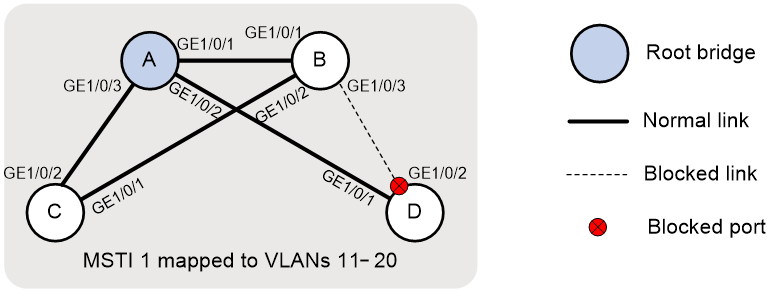
Based on the output, you can get the topology of MSTI 1, as shown in Figure 3.
Figure 3 Topology of MSTI 1
# Display dynamic VLANs on Device C.
[DeviceC] display vlan dynamic
Dynamic VLANs: 18
The dynamic VLANs include:
12-20, 22-30
# Display VLAN information on GigabitEthernet 1/0/2 of Device C.
[DeviceC] display interface gigabitethernet 1/0/2
...
Port link-type: Trunk
VLAN Passing: 1(default vlan), 11, 21
VLAN permitted: 1(default vlan), 11-30
Trunk port encapsulation: IEEE 802.1q
...
The output shows that:
· VLANs 1, 11, and 21 can pass through GigabitEthernet 1/0/2.
· GigabitEthernet 1/0/2 failed to learn dynamic VLANs.
Configuration files
|
|
IMPORTANT: Support for the port link-mode bridge command depends on the device model. |
· Device A:
#
sysname DeviceA
#
mvrp global enable
#
vlan 1
#
vlan 11 to 30
#
stp region-configuration
region-name test
instance 1 vlan 11 to 20
instance 2 vlan 21 to 30
active region-configuration
#
stp instance 0 to 1 root primary
stp global enable
#
interface GigabitEthernet1/0/1
port link-mode bridge
port link-type trunk
port trunk permit vlan 1 11 to 30
mvrp enable
#
interface GigabitEthernet1/0/2
port link-mode bridge
port link-type trunk
port trunk permit vlan 1 11 to 30
mvrp enable
#
interface GigabitEthernet1/0/3
port link-mode bridge
port link-type trunk
port trunk permit vlan 1 11 to 30
mvrp enable
#
· Device B:
#
sysname DeviceB
#
mvrp global enable
#
vlan 1
#
vlan 11
#
vlan 21
#
stp region-configuration
region-name test
instance 1 vlan 11 to 20
instance 2 vlan 21 to 30
active region-configuration
#
stp instance 2 root primary
stp global enable
#
interface GigabitEthernet1/0/1
port link-mode bridge
port link-type trunk
port trunk permit vlan 1 11 to 30
mvrp enable
#
interface GigabitEthernet1/0/2
port link-mode bridge
port link-type trunk
port trunk permit vlan 1 11 to 30
mvrp enable
#
interface GigabitEthernet1/0/3
port link-mode bridge
port link-type trunk
port trunk permit vlan 1 11 to 30
mvrp enable
#
· Device C:
#
sysname DeviceC
#
mvrp global enable
#
vlan 1
#
vlan 11
#
vlan 21
#
stp region-configuration
region-name test
instance 1 vlan 11 to 20
instance 2 vlan 21 to 30
active region-configuration
#
stp global enable
#
interface GigabitEthernet1/0/1
port link-mode bridge
port link-type trunk
port trunk permit vlan 1 11 to 30
mvrp enable
#
interface GigabitEthernet1/0/2
port link-mode bridge
port link-type trunk
port trunk permit vlan 1 11 to 30
mvrp enable
#
· Device D:
#
sysname DeviceD
#
mvrp global enable
#
vlan 1
#
vlan 11
#
vlan 21
#
stp region-configuration
region-name test
instance 1 vlan 11 to 20
instance 2 vlan 21 to 30
active region-configuration
#
stp global enable
#
interface GigabitEthernet1/0/1
port link-mode bridge
port link-type trunk
port trunk permit vlan 1 11 to 30
mvrp enable
#
interface GigabitEthernet1/0/2
port link-mode bridge
port link-type trunk
port trunk permit vlan 1 11 to 30
mvrp enable
#
