- Table of Contents
-
- H3C Fixed Port Campus Switches Configuration Examples-6W103
- 00-Applicable hardware and software versions
- 01-Login Management Configuration Examples
- 02-RBAC Configuration Examples
- 03-Software Upgrade Examples
- 04-ISSU Configuration Examples
- 05-Software Patching Examples
- 06-Ethernet Link Aggregation Configuration Examples
- 07-Port Isolation Configuration Examples
- 08-Spanning Tree Configuration Examples
- 09-VLAN Configuration Examples
- 10-VLAN Tagging Configuration Examples
- 11-DHCP Snooping Configuration Examples
- 12-Cross-Subnet Dynamic IP Address Allocation Configuration Examples
- 13-IPv6 over IPv4 Tunneling with OSPFv3 Configuration Examples
- 14-IPv6 over IPv4 GRE Tunnel Configuration Examples
- 15-GRE with OSPF Configuration Examples
- 16-OSPF Configuration Examples
- 17-IS-IS Configuration Examples
- 18-BGP Configuration Examples
- 19-Policy-Based Routing Configuration Examples
- 20-OSPFv3 Configuration Examples
- 21-IPv6 IS-IS Configuration Examples
- 22-Routing Policy Configuration Examples
- 23-IGMP Snooping Configuration Examples
- 24-IGMP Configuration Examples
- 25-MLD Snooping Configuration Examples
- 26-IPv6 Multicast VLAN Configuration Examples
- 27-ACL Configuration Examples
- 28-Traffic Policing Configuration Examples
- 29-GTS and Rate Limiting Configuration Examples
- 30-Traffic Filtering Configuration Examples
- 31-AAA Configuration Examples
- 32-Port Security Configuration Examples
- 33-Portal Configuration Examples
- 34-SSH Configuration Examples
- 35-IP Source Guard Configuration Examples
- 36-Ethernet OAM Configuration Examples
- 37-CFD Configuration Examples
- 38-DLDP Configuration Examples
- 39-VRRP Configuration Examples
- 40-BFD Configuration Examples
- 41-NTP Configuration Examples
- 42-SNMP Configuration Examples
- 43-NQA Configuration Examples
- 44-Mirroring Configuration Examples
- 45-sFlow Configuration Examples
- 46-OpenFlow Configuration Examples
- 47-MAC Address Table Configuration Examples
- 48-Static Multicast MAC Address Entry Configuration Examples
- 49-IP Unnumbered Configuration Examples
- 50-MVRP Configuration Examples
- 51-MCE Configuration Examples
- 52-Attack Protection Configuration Examples
- 53-Smart Link Configuration Examples
- 54-RRPP Configuration Examples
- 55-BGP Route Selection Configuration Examples
- 56-IS-IS Route Summarization Configuration Examples
- 57-VXLAN Configuration Examples
- 58-DRNI Configuration Examples
- 59-IRF 3.1 Configuration Examples
- 60-PTP Configuration Examples
- 61-S-MLAG Configuration Examples
- 62-Puppet Configuration Examples
- 63-802.1X Configuration Examples
- 64-MAC Authentication Configuration Examples
- 65-ISATAP Tunnel and 6to4 Tunnel Configuration Examples
- 66-BIDIR-PIM Configuration Examples
- 67-Congestion Avoidance and Queue Scheduling Configuration Examples
- 68-Basic MPLS Configuration Examples
- 69-MPLS L3VPN Configuration Examples
- 70-MPLS OAM Configuration Examples
- 71-EVPN-DCI over an MPLS L3VPN Network Configuration Examples
- 72-DRNI and EVPN Configuration Examples
- 73-Multicast VPN Configuration Examples
- 74-MPLS TE Configuration Examples
- 75-Control Plane-Based QoS Policy Configuration Examples
- 76-Priority Mapping and Queue Scheduling Configuration Examples
- 77-ARP Attack Protection Configuration Examples
- 78-IRF Software Upgrade Configuration Examples
- 79-IRF Member Replacement Configuration Examples
- 80-Layer 3 Multicast on Multicast Source-Side DR System Configuration Examples
- 81-EVPN Multicast Configuration Examples
- Related Documents
-
| Title | Size | Download |
|---|---|---|
| 40-BFD Configuration Examples | 439.83 KB |
Example: Configuring VRRP-BFD-Track collaboration
Applicable hardware and software versions
Configuring interface IP addresses
Configuring the interfaces that connect the gateways
Disabling the spanning tree feature on uplink interfaces
Configuring static routes from Device E and Device F to the virtual IP addresses of the VRRP groups
Example: Configuring BFD for static routing
Applicable hardware and software versions
Configuring interface IP addresses
Configuring BFD parameters on Device A
Example: Configuring BFD for RIP
Applicable hardware and software versions
Configuring interface IP addresses
Configuring BFD parameters on Device A
Example: Configuring BFD for OSPF
Applicable hardware and software versions
Configuring interface IP addresses
Example: Configuring BFD for IS-IS
Applicable hardware and software versions
Configuring interface IP addresses
Example: Configuring BFD for BGP
Applicable hardware and software versions
Configuring interface IP addresses
Example: Configuring BFD for PBR
Applicable hardware and software versions
Configuring interface IP addresses
Configuring routing policies on Device A
Configuring BFD parameters on Device A
Introduction
This document provides BFD configuration examples.
Prerequisites
This document is not restricted to specific software or hardware versions.
The configuration examples in this document were created and verified in a lab environment, and all the devices were started with the factory default configuration. When you are working on a live network, make sure you understand the potential impact of every command on your network.
This document assumes that you have basic knowledge of BFD, VRRP, Track, OSPF, and IS-IS.
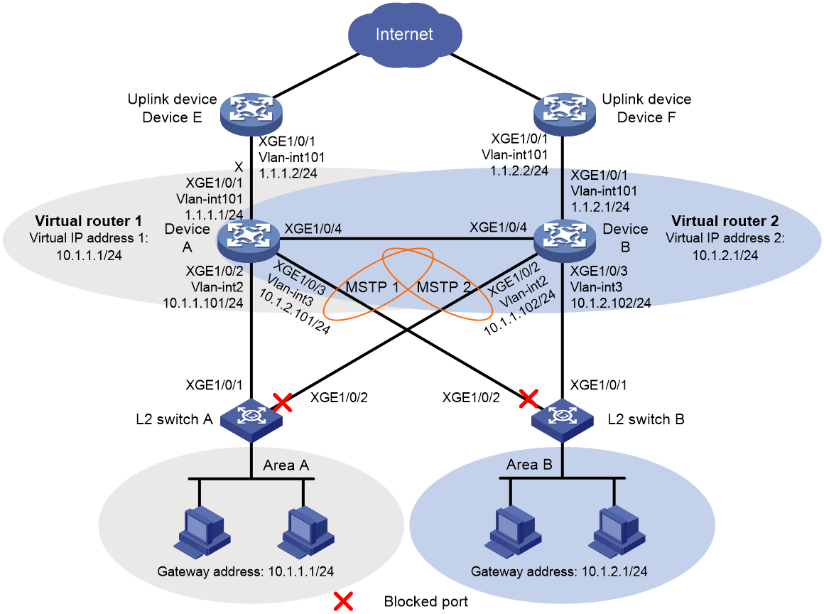
Example: Configuring VRRP-BFD-Track collaboration
Network configuration
As shown in Figure 1:
· Two distribution layer devices, Device A and Device B, are deployed at the egress of area A and area B.
· Device A and Device B belong to VRRP group 1 and VRRP group 2.
· Device A is the master in VRRP group 1. Device B is the master in VRRP group 2.
· The default gateway is VRRP group 1 for users in area A and VRRP group 2 for users in area B.
Configure VRRP-Track-BFD collaboration to meet the following requirements:
When Device A and Device B are operating correctly, they forward traffic for users in area A and area B, respectively.
· When one gateway device or the uplink of the device fails, BFD can detect the failure and the other device takes over to implement link switchover.
· When the downlink of a gateway device fails, L2 Switch A or L2 Switch B forwards user traffic to the gateway through interface GigabitEthernet 1/0/2. When the fault is cleared, L2 Switch A or L2 Switch B forwards user traffic to the gateway through interface GigabitEthernet 1/0/1.
Analysis
To meet the network requirements, you must perform the following tasks:
· For Device A to become the master in VRRP group 1, configure a higher priority (110) for Device A in VRRP group 1 (Device B uses the default priority 100). For Device B to become the master in VRRP group 2, configure a higher priority (110) for Device B in VRRP group 2 (Device A uses the default priority 100).
· To enable the failed master to forward traffic when it recovers, configure both VRRP groups to operate in preemptive mode.
· To enable Device A to communicate with Device B by using VRRP advertisement packets and BFD packets of different VLANs, configure the ports connecting Device A and Device B to allow packets from VLAN 2 and VLAN 3 to pass through.
· To eliminate Layer 2 loops, configure MSTP. Map VLAN 2 to MSTI 1 and map VLAN 3 to MSTI 2. The configuration traffic in MSTI 1 and MSTI 2 is forwarded through GigabitEthernet 1/0/1 of L2 Switch A and GigabitEthernet 1/0/1 of L2 Switch B, respectively.
· To prevent MSTP from blocking uplink interface GigabitEthernet 1/0/1 of Device A and Device B, disable the spanning tree feature on the interfaces.
Applicable hardware and software versions
The following matrix shows the hardware and software versions to which this configuration example is applicable:
|
Hardware |
Software version |
|
S6812 switch series S6813 switch series |
Release 66xx |
|
S6550XE-HI switch series |
Release 6008 and later |
|
S6525XE-HI switch series |
Release 6008 and later |
|
S5850 switch series |
Release 8005 and later |
|
S5570S-EI switch series |
Release 11xx |
|
S5560X-EI switch series |
Release 63xx, Release 65xx, Release 66xx |
|
S5560X-HI switch series |
Release 63xx, Release 65xx, Release 66xx |
|
S5500V2-EI switch series |
Release 63xx, Release 65xx, Release 66xx |
|
MS4520V2-30F switch |
Release 63xx, Release 65xx, Release 66xx |
|
MS4520V2-30C switch MS4520V2-54C switch |
Release 65xx, Release 66xx |
|
MS4520V2-28S switch MS4520V2-24TP switch |
Release 63xx |
|
S6520X-HI switch series S6520X-EI switch series |
Release 63xx, Release 65xx, Release 66xx |
|
S6520X-SI switch series S6520-SI switch series |
Release 63xx, Release 65xx, Release 66xx |
|
S5000-EI switch series |
Release 63xx, Release 65xx, Release 66xx |
|
MS4600 switch series |
Release 63xx, Release 65xx, Release 66xx |
|
ES5500 switch series |
Release 63xx, Release 65xx, Release 66xx |
|
S5560S-EI switch series S5560S-SI switch series |
Release 63xx |
|
S5500V3-24P-SI S5500V3-48P-SI |
Release 63xx |
|
S5500V3-SI switch series (excluding S5500V3-24P-SI and S5500V3-48P-SI) |
Release 11xx |
|
S5170-EI switch series |
Release 11xx |
|
S5130S-HI switch series S5130S-EI switch series S5130S-SI switch series S5130S-LI switch series |
Release 63xx |
|
S5120V3-EI switch series |
Not supported |
|
S5120V3-36F-SI S5120V3-28P-HPWR-SI S5120V3-54P-PWR-SI |
Not supported |
|
S5120V3-SI switch series (excluding S5120V3-36F-SI, S5120V3-28P-HPWR-SI, and S5120V3-54P-PWR-SI) |
Release 63xx |
|
S5120V3-LI switch series |
Release 63xx |
|
S3600V3-EI switch series |
Release 11xx |
|
S3600V3-SI switch series |
Release 11xx |
|
S5120V2-SI switch series S5120V2-LI switch series |
Release 63xx |
|
S3100V3-EI switch series S3100V3-SI switch series |
Release 63xx |
|
S5110V2 switch series |
Release 63xx |
|
S5110V2-SI switch series |
Release 63xx |
|
S5000V3-EI switch series S5000V5-EI switch series |
Release 63xx |
|
S5000E-X switch series S5000X-EI switch series |
Release 63xx |
|
E128C switch E152C switch E500C switch series E500D switch series |
Release 63xx |
|
MS4320V2 switch series MS4320V3 switch series MS4300V2 switch series MS4320 switch series MS4200 switch series |
Release 63xx |
|
WS5850-WiNet switch series |
Release 63xx |
|
WS5820-WiNet switch series WS5810-WiNet switch series |
Release 63xx |
|
WAS6000 switch series |
Release 63xx |
|
IE4300-12P-AC switch IE4300-12P-PWR switch IE4300-M switch series IE4320 switch series |
Release 63xx |
Restrictions and guidelines
When you configure VRRP-BFD-Track collaboration, follow these restrictions and guidelines:
· Make sure the VRRP versions on all devices of the VRRP group are the same.
· The source IP address for BFD echo packets cannot be on the same network segment as any local interface's IP address. Otherwise, a large number of ICMP redirect packets might be sent from the peer, resulting in link congestion.
· The virtual IP address of an IPv4 VRRP group and the downlink interface IP address of the VRRP group must be in the same subnet. Otherwise, the hosts in the subnet might fail to access external networks.
Procedures
Configuring interface IP addresses
1. Configure Device A:
<DeviceA> system-view
[DeviceA] vlan 101
[DeviceA-vlan101] port gigabitethernet 1/0/1
[DeviceA-vlan101] quit
[DeviceA] interface vlan-interface 101
[DeviceA-Vlan-interface101] ip address 1.1.1.1 24
[DeviceA-Vlan-interface101] quit
2. Configure other devices in the same way Device A is configured. (Details not shown.)
Configuring the interfaces that connect the gateways
1. Configure Device A:
# Configure GigabitEthernet 1/0/4 as a trunk port, remove the interface from VLAN 1, and assign it to VLAN 2 and VLAN 3.
[DeviceA] interface gigabitethernet 1/0/4
[DeviceA-GigabitEthernet1/0/4] port link-type trunk
[DeviceA-GigabitEthernet1/0/4] undo port trunk permit vlan 1
[DeviceA-GigabitEthernet1/0/4] port trunk permit vlan 2 to 3
[DeviceA-GigabitEthernet1/0/4] port trunk pvid vlan 2
[DeviceA-GigabitEthernet1/0/4] quit
2. Configure Device B:
# Configure GigabitEthernet 1/0/4 as a trunk port, remove the interface from VLAN 1, and assign it to VLAN 2 and VLAN 3.
[DeviceB] interface gigabitethernet 1/0/4
[DeviceB-GigabitEthernet1/0/4] port link-type trunk
[DeviceB-GigabitEthernet1/0/4] undo port trunk permit vlan 1
[DeviceB-GigabitEthernet1/0/4] port trunk permit vlan 2 to 3
[DeviceB-GigabitEthernet1/0/4] port trunk pvid vlan 2
[DeviceB-GigabitEthernet1/0/4] quit
Disabling the spanning tree feature on uplink interfaces
1. Disable the spanning tree feature on GigabitEthernet 1/0/1 of Device A:
[DeviceA] interface gigabitethernet 1/0/1
[DeviceA-GigabitEthernet1/0/1] undo stp enable
[DeviceA-GigabitEthernet1/0/1] quit
2. Disable the spanning tree feature on GigabitEthernet 1/0/1 of Device B:
[DeviceB] interface gigabitethernet 1/0/1
[DeviceB-GigabitEthernet1/0/1] undo stp enable
[DeviceB-GigabitEthernet1/0/1] quit
Configuring static routes from Device E and Device F to the virtual IP addresses of the VRRP groups
1. Configure Device E:
Configure static routes to the virtual IP addresses of VRRP group 1 and VRRP group 2.
<DeviceE> system-view
[DeviceE] ip route-static 10.1.1.0 255.255.255.0 1.1.1.1
[DeviceE] ip route-static 10.1.2.0 255.255.255.0 1.1.1.1
2. Configure Device F:
Configure static routes to the virtual IP addresses of VRRP group 1 and VRRP group 2.
<DeviceE> system-view
[DeviceF] ip route-static 10.1.1.0 255.255.255.0 1.1.2.1
[DeviceF] ip route-static 10.1.2.0 255.255.255.0 1.1.2.1
Configuring VRRP groups
1. Configure Device A:
# Configure the virtual IP address for VRRP group 1, set the preemption delay, and configure the priority of Device A in VRRP group 1.
[DeviceA] interface vlan-interface 2
[DeviceA-Vlan-interface2] vrrp vrid 1 virtual-ip 10.1.1.1
[DeviceA-Vlan-interface2] vrrp vrid 1 priority 110
[DeviceA-Vlan-interface2] vrrp vrid 1 preempt-mode delay 500
[DeviceA-Vlan-interface2] quit
# Configure the virtual IP address for VRRP group 2, and set the preemption delay.
[DeviceA] interface vlan-interface 3
[DeviceA-Vlan-interface3] vrrp vrid 2 virtual-ip 10.1.2.1
[DeviceA-Vlan-interface3] vrrp vrid 2 preempt-mode delay 500
[DeviceA–Vlan-interface3] quit
2. Configure Device B:
# Configure the virtual IP address for VRRP group 1, and set the preemption delay.
[DeviceB] interface vlan-interface 2
[DeviceB-Vlan-interface2] vrrp vrid 1 virtual-ip 10.1.1.1
[DeviceB-Vlan-interface2] vrrp vrid 1 preempt-mode delay 500
[DeviceB-Vlan-interface2] quit
# Configure the virtual IP address for VRRP group 2, set the preemption delay, and configure the priority of Device B in VRRP group 2.
[DeviceB] interface vlan-interface 3
[DeviceB-Vlan-interface3] vrrp vrid 2 virtual-ip 10.1.2.1
[DeviceB-Vlan-interface3] vrrp vrid 2 priority 110
[DeviceB-Vlan-interface3] vrrp vrid 2 preempt-mode delay 500
[DeviceB–Vlan-interface3] quit
Configuring BFD
1. Configure Device A:
# Configure the source IP address for BFD echo packets.
[DeviceA] bfd echo-source-ip 10.10.10.10
2. Configure Device B:
# Configure the source IP address for BFD echo packets.
[DeviceB] bfd echo-source-ip 11.11.11.11
Configuring Track
1. Configure Device A:
# Create track entry 1, and associate it with the BFD session to verify the reachability of Device E.
[DeviceA] track 1 bfd echo interface vlan-interface 101 remote ip 1.1.1.2 local ip 1.1.1.1
[DeviceA-track-1] quit
# Associate VRRP group 1 with track entry 1 and decrease the router priority by 20 when the state of track entry 1 changes to negative.
[DeviceA] interface vlan-interface 2
[DeviceA-Vlan-interface2] vrrp vrid 1 track 1 priority reduced 20
[DeviceA-Vlan-interface2] quit
2. Configure Device B:
# Create track entry 1, and associate it with the BFD session to verify the reachability of Device F.
[DeviceB] track 1 bfd echo interface vlan-interface 101 remote ip 1.1.2.2 local ip 1.1.2.1
[DeviceB-track-1] quit
# Associate VRRP group 2 with track entry 1 and decrease the router priority by 20 when the state of track entry 1 changes to negative.
[DeviceB] interface vlan-interface 3
[DeviceB-Vlan-interface3] vrrp vrid 2 track 1 priority reduced 20
[DeviceB-Vlan-interface3] quit
Configuring MSTP
1. Configure Device A:
[DeviceA] stp region-configuration
[DeviceA-mst-region] region-name vrrp
[DeviceA-mst-region] instance 1 vlan 2
[DeviceA-mst-region] instance 2 vlan 3
[DeviceA-mst-region] active region-configuration
[DeviceA-mst-region] quit
[DeviceA] stp instance 1 root primary
[DeviceA] stp instance 2 root secondary
[DeviceA] stp global enable
2. Configure Device B:
[DeviceB] stp region-configuration
[DeviceB-mst-region] region-name vrrp
[DeviceB-mst-region] instance 1 vlan 2
[DeviceB-mst-region] instance 2 vlan 3
[DeviceB-mst-region] active region-configuration
[DeviceB-mst-region] quit
[DeviceB] stp instance 2 root primary
[DeviceB] stp instance 1 root secondary
[DeviceB] stp global enable
3. Configure L2 Switch A:
<SwitchA> system-view
[SwitchA] stp region-configuration
[SwitchA-mst-region] region-name vrrp
[SwitchA-mst-region] instance 1 vlan 2
[SwitchA-mst-region] active region-configuration
[SwitchA-mst-region] quit
[SwitchA] stp global enable
4. Configure L2 Switch B:
<SwitchB> system-view
[SwitchB] stp region-configuration
[SwitchB-mst-region] region-name vrrp
[SwitchB-mst-region] instance 2 vlan 3
[SwitchB-mst-region] active region-configuration
[SwitchB-mst-region] quit
Verifying the configuration
1. Verify that the hosts in the LAN can access the external network when Device A and Device B are operating correctly:
# Ping 1.1.1.2 from host A in area A.
<host A> ping 1.1.1.2
PING 1.1.1.2 (1.1.1.2): 56 data bytes
56 bytes from 1.1.1.2: seq=0 ttl=128 time=22.43 ms
56 bytes from 1.1.1.2: seq=1 ttl=128 time=7.17 ms
56 bytes from 1.1.1.2: seq=2 ttl=128 time=8.91 ms
56 bytes from 1.1.1.2: seq=3 ttl=128 time=7.45 ms
56 bytes from 1.1.1.2: seq=4 ttl=128 time=9.11 ms
--- 1.1.1.2 ping statistics ---
5 packets transmitted, 5 packets received, 0% packet loss
round-trip min/avg/max = 7.17/11.01/22.43 ms
# Ping 1.1.2.2 from host C in area B.
<host C> ping 1.1.2.2
PING 1.1.2.2 (1.1.2.2): 56 data bytes
56 bytes from 1.1.2.2: seq=0 ttl=128 time=22.43 ms
56 bytes from 1.1.2.2: seq=1 ttl=128 time=7.17 ms
56 bytes from 1.1.2.2: seq=2 ttl=128 time=8.91 ms
56 bytes from 1.1.2.2: seq=3 ttl=128 time=7.45 ms
56 bytes from 1.1.2.2: seq=4 ttl=128 time=9.11 ms
--- 1.1.2.2 ping statistics ---
5 packets transmitted, 5 packets received, 0% packet loss
round-trip min/avg/max = 7.17/11.01/22.43 ms
The output shows that the hosts in area A and area B can access the external network.
# Display BFD session information on Device A.
[DeviceA] display bfd session
Total Session Num: 1 Up Session Num: 1 Init Mode: Active
IPv4 session working in echo mode:
LD SourceAddr DestAddr State Holdtime Interface
129 1.1.1.1 1.1.1.2 Up 500ms Vlan101
The output shows that a BFD session has been established.
# Display detailed VRRP group information on Device A.
[DeviceA] display vrrp verbose
IPv4 Virtual Router Information:
Running mode : Standard
Total number of virtual routers : 2
Interface Vlan-interface2
VRID : 1 Adver Timer : 100
Admin Status : Up State : Master
Config Pri : 110 Running Pri : 110
Preempt Mode : Yes Delay Time : 500
Auth Type : None
Virtual IP : 10.1.1.1
Virtual MAC : 0000-5e00-0101
Master IP : 10.1.1.101
VRRP Track Information:
Track Object : 1 State : Positive Pri Reduced : 20
Interface Vlan-interface3
VRID : 2 Adver Timer : 100
Admin Status : Up State : Backup
Config Pri : 100 Running Pri : 100
Preempt Mode : Yes Delay Time : 500
Become Master : 3600ms left
Auth Type : None
Virtual IP : 10.1.2.1
Virtual MAC : 0000-5e00-0102
Master IP : 10.1.2.102
# Display detailed VRRP group information on Device B.
[DeviceB] display vrrp verbose
IPv4 Virtual Router Information:
Running mode : Standard
Total number of virtual routers : 2
Interface Vlan-interface2
VRID : 1 Adver Timer : 100
Admin Status : Up State : Backup
Config Pri : 100 Running Pri : 100
Preempt Mode : Yes Delay Time : 500
Become Master : 3100ms left
Auth Type : None
Virtual IP : 10.1.1.1
Virtual MAC : 0000-5e00-0101
Master IP : 10.1.1.101
Interface Vlan-interface3
VRID : 2 Adver Timer : 100
Admin Status : Up State : Master
Config Pri : 110 Running Pri : 110
Preempt Mode : Yes Delay Time : 500
Auth Type : None
Virtual IP : 10.1.2.1
Virtual MAC : 0000-5e00-0102
Master IP : 10.1.2.102
VRRP Track Information:
Track Object : 1 State : Positive Pri Reduced : 20
The output shows the following information:
¡ In VRRP group 1, Device A is the master, and Device B is the backup. Hosts that use default gateway 10.1.1.1/24 access the Internet through Device A.
¡ In VRRP group 2, Device B is the master, and Device A is the backup. Hosts that use default gateway 10.1.2.1/24 access the Internet through Device B.
2. Verify that the hosts in the LAN can access the external network when the uplink monitored by Device A fails:
# Ping 1.1.1.2 from host A in area A.
<host A> ping 1.1.1.2
PING 1.1.1.2 (1.1.1.2): 56 data bytes
56 bytes from 1.1.1.2: seq=0 ttl=128 time=22.43 ms
56 bytes from 1.1.1.2: seq=1 ttl=128 time=7.17 ms
56 bytes from 1.1.1.2: seq=2 ttl=128 time=8.91 ms
56 bytes from 1.1.1.2: seq=3 ttl=128 time=7.45 ms
56 bytes from 1.1.1.2: seq=4 ttl=128 time=9.11 ms
--- 1.1.1.2 ping statistics ---
5 packets transmitted, 5 packets received, 0% packet loss
round-trip min/avg/max = 7.17/11.01/22.43 ms
# Ping 1.1.2.2 from host C in area B.
<host C> ping 1.1.2.2
PING 1.1.2.2 (1.1.2.2): 56 data bytes
56 bytes from 1.1.2.2: seq=0 ttl=128 time=22.43 ms
56 bytes from 1.1.2.2: seq=1 ttl=128 time=7.17 ms
56 bytes from 1.1.2.2: seq=2 ttl=128 time=8.91 ms
56 bytes from 1.1.2.2: seq=3 ttl=128 time=7.45 ms
56 bytes from 1.1.2.2: seq=4 ttl=128 time=9.11 ms
--- 1.1.2.2 ping statistics ---
5 packets transmitted, 5 packets received, 0% packet loss
round-trip min/avg/max = 7.17/11.01/22.43 ms
The output shows that the hosts in area A and area B can access the external network.
# Display BFD session information on Device A.
[DeviceA] display bfd session
Total Session Num: 1 Up Session Num: 0 Init Mode: Active
IPv4 session working in echo mode:
LD SourceAddr DestAddr State Holdtime Interface
129 1.1.1.1 1.1.1.2 Down / Vlan101
The output shows that the BFD session has been terminated.
# Display detailed VRRP group information on Device B.
[DeviceB] display vrrp verbose
IPv4 Virtual Router Information:
Running mode : Standard
Total number of virtual routers : 2
Interface Vlan-interface2
VRID : 1 Adver Timer : 100
Admin Status : Up State : Master
Config Pri : 100 Running Pri : 100
Preempt Mode : Yes Delay Time : 500
Auth Type : None
Virtual IP : 10.1.1.1
Virtual MAC : 0000-5e00-0101
Master IP : 10.1.1.102
Interface Vlan-interface3
VRID : 2 Adver Timer : 100
Admin Status : Up State : Master
Config Pri : 110 Running Pri : 110
Preempt Mode : Yes Delay Time : 500
Auth Type : None
Virtual IP : 10.1.2.1
Virtual MAC : 0000-5e00-0102
Master IP : 10.1.2.102
VRRP Track Information:
Track Object : 1 State : Positive Pri Reduced : 20
The output shows that Device B becomes the master in VRRP group 1. Hosts in area A access the external network through Device B.
# When the fault is cleared, display BFD session information on Device A.
[DeviceA] display bfd session
Total Session Num: 1 Up Session Num: 1 Init Mode: Active
IPv4 session working in echo mode:
LD SourceAddr DestAddr State Holdtime Interface
129 1.1.1.1 1.1.1.2 Up 1000ms Vlan101
The output shows that the BFD session is resumed.
# Display detailed VRRP group information on Device A.
[DeviceA] display vrrp verbose
IPv4 Virtual Router Information:
Running mode : Standard
Total number of virtual routers : 2
Interface Vlan-interface2
VRID : 1 Adver Timer : 100
Admin Status : Up State : Master
Config Pri : 110 Running Pri : 110
Preempt Mode : Yes Delay Time : 500
Auth Type : None
Virtual IP : 10.1.1.1
Virtual MAC : 0000-5e00-0101
Master IP : 10.1.1.101
VRRP Track Information:
Track Object : 1 State : Positive Pri Reduced : 20
Interface Vlan-interface3
VRID : 2 Adver Timer : 100
Admin Status : Up State : Backup
Config Pri : 100 Running Pri : 100
Preempt Mode : Yes Delay Time : 500
Become Master : 3550ms left
Auth Type : None
Virtual IP : 10.1.2.1
Virtual MAC : 0000-5e00-0102
Master IP : 10.1.2.102
The output shows that Device A resumes its priority and becomes the master in VRRP group 1 again. Hosts in area B access the external network through Device A.
Configuration files
|
|
NOTE: Support for the port link-mode bridge command depends on the device model. |
· Device A:
#
bfd echo-source-ip 10.10.10.10
#
vlan 2 to 3
#
vlan 101
#
stp region-configuration
region-name vrrp
instance 1 vlan 2
instance 2 vlan 3
active region-configuration
#
stp instance 1 root primary
stp instance 2 root secondary
stp global enable
#
interface Vlan-interface2
ip address 10.1.1.101 255.255.255.0
vrrp vrid 1 virtual-ip 10.1.1.1
vrrp vrid 1 priority 110
vrrp vrid 1 preempt-mode delay 500
vrrp vrid 1 track 1 priority reduced 20
#
interface Vlan-interface3
ip address 10.1.2.101 255.255.255.0
vrrp vrid 2 virtual-ip 10.1.2.1
vrrp vrid 2 preempt-mode delay 500
#
interface Vlan-interface101
ip address 1.1.1.1 255.255.255.0
#
interface GigabitEthernet1/0/1
port link-mode bridge
port access vlan 101
undo stp enable
#
interface GigabitEthernet1/0/2
port link-mode bridge
port access vlan 2
#
interface GigabitEthernet1/0/3
port link-mode bridge
port access vlan 3
#
interface GigabitEthernet1/0/4
port link-mode bridge
port link-type trunk
undo port trunk permit vlan 1
port trunk permit vlan 2 to 3
port trunk pvid vlan 2
#
track 1 bfd echo interface Vlan-interface101 remote ip 1.1.1.2 local ip 1.1.1.1
· Device B:
#
bfd echo-source-ip 11.11.11.11
#
vlan 2 to 3
#
vlan 101
#
stp region-configuration
region-name vrrp
instance 1 vlan 2
instance 2 vlan 3
active region-configuration
#
stp instance 1 root secondary
stp instance 2 root primary
stp global enable
#
interface Vlan-interface2
ip address 10.1.1.102 255.255.255.0
vrrp vrid 1 virtual-ip 10.1.1.1
vrrp vrid 1 preempt-mode delay 500
#
interface Vlan-interface3
ip address 10.1.2.102 255.255.255.0
vrrp vrid 2 virtual-ip 10.1.2.1
vrrp vrid 2 priority 110
vrrp vrid 2 preempt-mode delay 500
vrrp vrid 2 track 1 priority reduced 20
#
interface Vlan-interface101
ip address 1.1.2.1 255.255.255.0
#
interface GigabitEthernet1/0/1
port link-mode bridge
port access vlan 101
undo stp enable
#
interface GigabitEthernet1/0/2
port link-mode bridge
port access vlan 2
#
interface GigabitEthernet1/0/3
port link-mode bridge
port access vlan 3
#
interface GigabitEthernet1/0/4
port link-mode bridge
port link-type trunk
undo port trunk permit vlan 1
port trunk permit vlan 2 to 3
port trunk pvid vlan 2
#
track 1 bfd echo interface Vlan-interface101 remote ip 1.1.2.2 local ip 1.1.2.1
· L2 Switch A:
#
vlan 2
#
stp region-configuration
region-name vrrp
instance 1 vlan 2
active region-configuration
#
stp global enable
#
interface GigabitEthernet1/0/1
port link-mode bridge
port access vlan 2
#
interface GigabitEthernet1/0/2
port link-mode bridge
port access vlan 2
· L2 Switch B:
#
vlan 3
#
stp region-configuration
region-name vrrp
instance 2 vlan 3
active region-configuration
#
stp global enable
#
interface GigabitEthernet1/0/1
port link-mode bridge
port access vlan 3
#
interface GigabitEthernet1/0/2
port link-mode bridge
port access vlan 3
· Device E:
#
vlan 101
#
interface Vlan-interface101
ip address 1.1.1.2 255.255.255.0
#
interface GigabitEthernet1/0/1
port link-mode bridge
port access vlan 101
#
ip route-static 10.1.1.0 255.255.255.0 1.1.1.1
ip route-static 10.1.2.0 255.255.255.0 1.1.1.1
· Device F:
#
vlan 101
#
interface Vlan-interface101
ip address 1.1.2.2 255.255.255.0
#
interface GigabitEthernet1/0/1
port link-mode bridge
port access vlan 101
#
ip route-static 10.1.1.0 255.255.255.0 1.1.2.1
ip route-static 10.1.2.0 255.255.255.0 1.1.2.1
Example: Configuring BFD for static routing
Network configuration
· Device A has two paths to reach Device B: one over a Layer 2 switch, and the other over Device C.
· A Layer 2 switch connects Device A and Device B.
Because Device B does not support BFD, enable BFD echo packet mode on Device A. When the link between Device B and the Layer 2 switch fails, Device A switches the path over Device C to reach Device B.
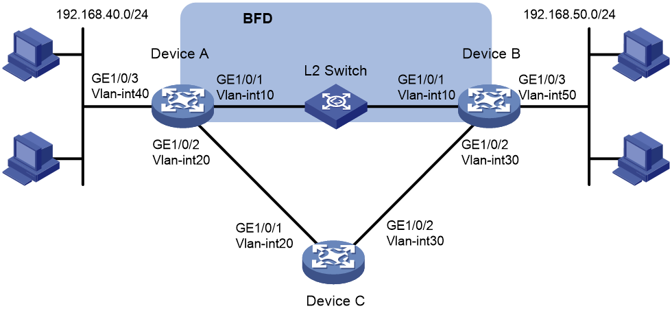
Table 1 Interface and IP address assignment
|
Device |
Interface |
IP address |
|
Device A |
Vlan-int10 |
192.168.10.101/24 |
|
Device A |
Vlan-int20 |
192.168.20.101/24 |
|
Device A |
Vlan-int40 |
192.168.40.101/24 |
|
Device B |
Vlan-int10 |
192.168.10.102/24 |
|
Device B |
Vlan-int30 |
192.168.30.101/24 |
|
Device B |
Vlan-int50 |
192.168.50.101/24 |
|
Device C |
Vlan-int20 |
192.168.20.102/24 |
|
Device C |
Vlan-int30 |
192.168.30.102/24 |
Applicable hardware and software versions
The following matrix shows the hardware and software versions to which this configuration example is applicable:
|
Hardware |
Software version |
|
S6812 switch series S6813 switch series |
Release 66xx |
|
S6550XE-HI switch series |
Release 6008 and later |
|
S6525XE-HI switch series |
Release 6008 and later |
|
S5850 switch series |
Release 8005 and later |
|
S5570S-EI switch series |
Release 11xx |
|
S5560X-EI switch series |
Release 63xx, Release 65xx, Release 66xx |
|
S5560X-HI switch series |
Release 63xx, Release 65xx, Release 66xx |
|
S5500V2-EI switch series |
Release 63xx, Release 65xx, Release 66xx |
|
MS4520V2-30F switch |
Release 63xx, Release 65xx, Release 66xx |
|
MS4520V2-30C switch MS4520V2-54C switch |
Release 65xx, Release 66xx |
|
MS4520V2-28S switch MS4520V2-24TP switch |
Release 63xx |
|
S6520X-HI switch series S6520X-EI switch series |
Release 63xx, Release 65xx, Release 66xx |
|
S6520X-SI switch series S6520-SI switch series |
Release 63xx, Release 65xx, Release 66xx |
|
S5000-EI switch series |
Release 63xx, Release 65xx, Release 66xx |
|
MS4600 switch series |
Release 63xx, Release 65xx, Release 66xx |
|
ES5500 switch series |
Release 63xx, Release 65xx, Release 66xx |
|
S5560S-EI switch series S5560S-SI switch series |
Release 63xx |
|
S5500V3-24P-SI S5500V3-48P-SI |
Release 63xx |
|
S5500V3-SI switch series (excluding S5500V3-24P-SI and S5500V3-48P-SI) |
Release 11xx |
|
S5170-EI switch series |
Release 11xx |
|
S5130S-HI switch series S5130S-EI switch series S5130S-SI switch series S5130S-LI switch series |
Not supported |
|
S5120V2-SI switch series S5120V2-LI switch series |
Not supported |
|
S5120V3-EI switch series |
Release 11xx |
|
S5120V3-36F-SI S5120V3-28P-HPWR-SI S5120V3-54P-PWR-SI |
Release 11xx |
|
S5120V3-SI switch series (excluding S5120V3-36F-SI, S5120V3-28P-HPWR-SI, and S5120V3-54P-PWR-SI) |
Not supported |
|
S5120V3-LI switch series |
Not supported |
|
S3600V3-EI switch series |
Release 11xx |
|
S3600V3-SI switch series |
Release 11xx |
|
S3100V3-EI switch series S3100V3-SI switch series |
Not supported |
|
S5110V2 switch series |
Not supported |
|
S5110V2-SI switch series |
Not supported |
|
S5000V3-EI switch series S5000V5-EI switch series |
Not supported |
|
S5000E-X switch series S5000X-EI switch series |
Not supported |
|
E128C switch E152C switch |
Release 63xx |
|
E500C switch series E500D switch series |
Not supported |
|
MS4320V2 switch series MS4320V3 switch series MS4300V2 switch series MS4320 switch series MS4200 switch series |
Not supported |
|
WS5850-WiNet switch series |
Release 63xx |
|
WS5820-WiNet switch series WS5810-WiNet switch series |
Not supported |
|
WAS6000 switch series |
Release 63xx |
|
IE4300-12P-AC switch IE4300-12P-PWR switch IE4300-M switch series IE4320 switch series |
Release 63xx |
Restrictions and guidelines
The source IP address for BFD echo packets cannot be on the same network segment as any local interface's IP address. Otherwise, a large number of ICMP redirect packets might be sent from the peer, resulting in link congestion.
Procedures
Configuring interface IP addresses
1. Configure Device A:
<DeviceA> system-view
[DeviceA] vlan 10
[DeviceA-vlan10] port gigabitethernet 1/0/1
[DeviceA-vlan10] quit
[DeviceA] interface vlan-interface 10
[DeviceA-Vlan-interface10] ip address 192.168.10.101 24
[DeviceA-Vlan-interface10] quit
2. Configure other devices in the same way Device A is configured. (Details not shown.)
Configuring static routes
1. Configure Device A:
# Configure two static routes with the same destination network 192.168.50.0/24 and different preferences. Configure the BFD echo packet mode for the preferred static route (Device A –> L2 Switch–> Device B).
[DeviceA] ip route-static 192.168.50.0 24 vlan-interface 10 192.168.10.102 bfd echo-packet
[DeviceA] ip route-static 192.168.50.0 24 vlan-interface 20 192.168.20.102 preference 65
2. Configure Device B:
# Configure two static routes with the same destination network 192.168.40.0/24 and different preferences. Configure the BFD echo packet mode for the preferred static route (Device B –> L2 Switch–> Device A).
[DeviceB] ip route-static 192.168.40.0 24 vlan-interface 10 192.168.10.101
[DeviceB] ip route-static 192.168.40.0 24 vlan-interface 30 192.168.30.102 preference 65
3. Configure Device C:
# Configure static routes with destination networks 192.168.40.0/24 and 192.168.50.0/24.
[DeviceC] ip route-static 192.168.40.0 24 vlan-interface 20 192.168.20.101
[DeviceC] ip route-static 192.168.50.0 24 vlan-interface 30 192.168.30.101
Configuring BFD parameters on Device A
# Configure the source IP address for BFD echo packets.
[DeviceA] bfd echo-source-ip 10.10.10.10
# Configure the minimum interval for receiving BFD echo packets and the single-hop detection time multiplier.
[DeviceA] interface vlan-interface 10
[DeviceA-Vlan-interface10] bfd min-echo-receive-interval 100
[DeviceA-Vlan-interface10] bfd detect-multiplier 3
[DeviceA-Vlan-interface10] quit
Verifying the configuration
1. Verify the configuration when Device A and Device B and the link between them are operating correctly:
# Display static route information on Device A.
[DeviceA] display ip routing-table protocol static
Summary Count : 1
Static Routing table Status : <Active>
Summary Count : 1
Destination/Mask Proto Pre Cost NextHop Interface
192.168.50.0/24 Static 60 0 192.168.10.102 Vlan10
Static Routing table Status : <Inactive>
Summary Count : 0
The output shows that Device A communicates with Device B through the Layer 2 switch.
# Display BFD session information on Device A.
[DeviceA] display bfd session
Total Session Num: 1 Up Session Num: 1 Init Mode: Active
IPv4 session working in echo mode:
LD SourceAddr DestAddr State Holdtime Interface
67 192.168.10.101 192.168.10.102 Up 300ms Vlan10
The output shows that a BFD session has been established.
2. Verify the configuration when the link between Device B and the Layer 2 switch is faulty:
# Display static route information on Device A.
[DeviceA] display ip routing-table protocol static
Summary Count : 1
Static Routing table Status : <Active>
Summary Count : 1
Destination/Mask Proto Pre Cost NextHop Interface
192.168.50.0/24 Static 65 0 192.168.20.102 Vlan20
Static Routing table Status : <Inactive>
Summary Count : 0
The output shows that Device A communicates with Device B through Device C.
Configuration files
|
|
NOTE: Support for the port link-mode bridge command depends on the device model. |
· Device A:
#
bfd echo-source-ip 10.10.10.10
#
vlan 10
#
vlan 20
#
vlan 40
#
interface Vlan-interface10
ip address 192.168.10.101 255.255.255.0
bfd min-echo-receive-interval 100
bfd detect-multiplier 3
#
interface Vlan-interface20
ip address 192.168.20.101 255.255.255.0
#
interface Vlan-interface40
ip address 192.168.40.101 255.255.255.0
#
interface GigabitEthernet1/0/1
port link-mode bridge
port access vlan 10
#
interface GigabitEthernet1/0/2
port link-mode bridge
port access vlan 20
#
interface GigabitEthernet1/0/3
port link-mode bridge
port access vlan 40
#
ip route-static 192.168.50.0 24 Vlan-interface10 192.168.10.102 bfd echo-packet
ip route-static 192.168.50.0 24 Vlan-interface20 192.168.20.102 preference 65
#
· Device B:
#
vlan 10
#
vlan 30
#
vlan 50
#
interface Vlan-interface10
ip address 192.168.10.102 255.255.255.0
#
interface Vlan-interface30
ip address 192.168.30.101 255.255.255.0
#
interface Vlan-interface50
ip address 192.168.50.101 255.255.255.0
#
interface GigabitEthernet1/0/1
port link-mode bridge
port access vlan 10
#
interface GigabitEthernet1/0/2
port link-mode bridge
port access vlan 30
#
interface GigabitEthernet1/0/3
port link-mode bridge
port access vlan 50
#
ip route-static 192.168.40.0 24 Vlan-interface10 192.168.10.101
ip route-static 192.168.40.0 24 Vlan-interface30 192.168.30.102 preference 65
#
· Device C:
#
vlan 20
#
vlan 30
#
interface Vlan-interface20
ip address 192.168.20.102 255.255.255.0
#
interface Vlan-interface30
ip address 192.168.30.102 255.255.255.0
#
interface GigabitEthernet1/0/1
port link-mode bridge
port access vlan 20
#
interface GigabitEthernet1/0/2
port link-mode bridge
port access vlan 30
#
ip route-static 192.168.40.0 24 Vlan-interface20 192.168.20.101
ip route-static 192.168.50.0 24 Vlan-interface30 192.168.30.101
#
Example: Configuring BFD for RIP
Network configuration
As shown in Figure 3, Device A, Device B, and Device C run RIP. Device A and Device C are connected through a Layer 2 switch.
Enable BFD echo packet mode on Device A (Device C does not support BFD) to monitor the path over the Layer 2 switch. When BFD detects a link failure, it notifies RIP to switch to the path over Device B.
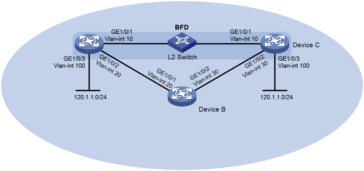
Table 2 Interface and IP address assignment
|
Device |
Interface |
IP address |
|
Device A |
Vlan-int10 |
10.1.0.101/24 |
|
Device A |
Vlan-int20 |
192.168.0.101/24 |
|
Device A |
Vlan-int100 |
120.1.1.1/24 |
|
Device B |
Vlan-int20 |
192.168.0.102/24 |
|
Device B |
Vlan-int30 |
13.1.1.101/24 |
|
Device C |
Vlan-int10 |
10.1.0.102/24 |
|
Device C |
Vlan-int30 |
13.1.1.102/24 |
|
Device C |
Vlan-int100 |
121.1.1.1/24 |
Applicable hardware and software versions
The following matrix shows the hardware and software versions to which this configuration example is applicable:
|
Hardware |
Software version |
|
S6812 switch series S6813 switch series |
Release 66xx |
|
S6550XE-HI switch series |
Release 6008 and later |
|
S6525XE-HI switch series |
Release 6008 and later |
|
S5850 switch series |
Release 8005 and later |
|
S5570S-EI switch series |
Release 11xx |
|
S5560X-EI switch series |
Release 63xx, Release 65xx, Release 66xx |
|
S5560X-HI switch series |
Release 63xx, Release 65xx, Release 66xx |
|
S5500V2-EI switch series |
Release 63xx, Release 65xx, Release 66xx |
|
MS4520V2-30F switch |
Release 63xx, Release 65xx, Release 66xx |
|
MS4520V2-30C switch MS4520V2-54C switch |
Release 65xx, Release 66xx |
|
MS4520V2-28S switch MS4520V2-24TP switch |
Release 63xx |
|
S6520X-HI switch series S6520X-EI switch series |
Release 63xx, Release 65xx, Release 66xx |
|
S6520X-SI switch series S6520-SI switch series |
Release 63xx, Release 65xx, Release 66xx |
|
S5000-EI switch series |
Release 63xx, Release 65xx, Release 66xx |
|
MS4600 switch series |
Release 63xx, Release 65xx, Release 66xx |
|
ES5500 switch series |
Release 63xx, Release 65xx, Release 66xx |
|
S5560S-EI switch series S5560S-SI switch series |
Release 63xx |
|
S5500V3-24P-SI S5500V3-48P-SI |
Release 63xx |
|
S5500V3-SI switch series (excluding S5500V3-24P-SI and S5500V3-48P-SI) |
Release 11xx |
|
S5170-EI switch series |
Release 11xx |
|
S5130S-HI switch series S5130S-EI switch series S5130S-SI switch series S5130S-LI switch series |
Not supported |
|
S5120V2-SI switch series S5120V2-LI switch series |
Not supported |
|
S5120V3-EI switch series |
Release 11xx |
|
S5120V3-36F-SI S5120V3-28P-HPWR-SI S5120V3-54P-PWR-SI |
Release 11xx |
|
S5120V3-SI switch series (excluding S5120V3-36F-SI, S5120V3-28P-HPWR-SI, and S5120V3-54P-PWR-SI) |
Not supported |
|
S5120V3-LI switch series |
Not supported |
|
S3600V3-EI switch series |
Release 11xx |
|
S3600V3-SI switch series |
Release 11xx |
|
S3100V3-EI switch series S3100V3-SI switch series |
Not supported |
|
S5110V2 switch series |
Not supported |
|
S5110V2-SI switch series |
Not supported |
|
S5000V3-EI switch series S5000V5-EI switch series |
Not supported |
|
S5000E-X switch series S5000X-EI switch series |
Not supported |
|
E128C switch E152C switch |
Release 63xx |
|
E500C switch series E500D switch series |
Not supported |
|
MS4320V2 switch series MS4320V3 switch series MS4300V2 switch series MS4320 switch series MS4200 switch series |
Not supported |
|
WS5850-WiNet switch series |
Release 63xx |
|
WS5820-WiNet switch series WS5810-WiNet switch series |
Not supported |
|
WAS6000 switch series |
Release 63xx |
|
IE4300-12P-AC switch IE4300-12P-PWR switch IE4300-M switch series IE4320 switch series |
Release 63xx |
Restrictions and guidelines
The source IP address for BFD echo packets cannot be on the same network segment as any local interface's IP address. Otherwise, a large number of ICMP redirect packets might be sent from the peer, resulting in link congestion.
Procedures
Configuring interface IP addresses
1. Configure Device A:
<DeviceA> system-view
[DeviceA] vlan 10
[DeviceA-vlan10] port gigabitethernet 1/0/1
[DeviceA-vlan10] quit
[DeviceA] interface vlan-interface10
[DeviceA-Vlan-interface10] ip address 10.1.0.101 24
[DeviceA-Vlan-interface10] quit
2. Configure other devices in the same way Device A is configured. (Details not shown.)
Configuring RIP
1. Configure Device A:
# Configure basic RIP functions, import direct routes, and enable BFD for RIP.
<DeviceA> system-view
[DeviceA] rip 1
[DeviceA-rip-1] version 2
[DeviceA-rip-1] undo summary
[DeviceA-rip-1] network 10.1.0.0
[DeviceA-rip-1] network 192.168.0.0
[DeviceA-rip-1] import-route direct
[DeviceA-rip-1] quit
[DeviceA] interface vlan-interface 10
[DeviceA-Vlan-interface10] rip bfd enable
[DeviceA-Vlan-interface10] quit
2. Configure Device B:
# Configure basic RIP functions, and import direct routes.
<DeviceB> system-view
[DeviceB] rip 1
[DeviceB-rip-1] version 2
[DeviceB-rip-1] undo summary
[DeviceB-rip-1] network 192.168.0.0
[DeviceB-rip-1] network 13.1.1.0
[DeviceB-rip-1] import-route direct
[DeviceB-rip-1] quit
3. Configure Device C:
# Configure basic RIP functions, and import direct routes.
<DeviceC> system-view
[DeviceC] rip 1
[DeviceC-rip-1] version 2
[DeviceC-rip-1] undo summary
[DeviceC-rip-1] network 10.1.0.0
[DeviceC-rip-1] network 13.1.1.0
[DeviceC-rip-1] import-route direct
[DeviceC-rip-1] quit
Configuring BFD parameters on Device A
# Configure the source IP address for BFD echo packets.
[DeviceA] bfd echo-source-ip 11.11.11.11
# Configure the minimum interval for receiving BFD echo packets and the single-hop detection time multiplier.
[DeviceA] interface vlan-interface 10
[DeviceA-Vlan-interface10] bfd min-echo-receive-interval 100
[DeviceA-Vlan-interface10] bfd detect-multiplier 3
[DeviceA-Vlan-interface10] quit
Verifying the configuration
# Display BFD session information on Device A.
[DeviceA] display bfd session verbose
Total Session Num: 1 Up Session Num: 1 Init Mode: Active
IPv4 session working in echo mode:
Local Discr: 2049
Source IP: 10.1.0.101 Destination IP: 10.1.0.102
Session State: Up Interface: Vlan-interface10
Hold Time: 300ms Act Tx Inter: 100ms
Min Rx Inter: 100ms Detect Inter: 300ms
Rx Count: 0 Tx Count: 910
Connect Type: Direct Running Up for: 00:00:46
Detect Mode: Async Slot: 1
Protocol: RIP
Version: 1
Diag Info: No Diagnostic
The output shows that a BFD session has been established and is up.
# (Release 63xx) Display information about the routes to network 121.1.1.0/24 on Device A.
<DeviceA> display ip routing-table 121.1.1.0 24 verbose
Summary Count : 1
Destination: 121.1.1.0/24
Protocol: RIP
Process ID: 1
SubProtID: 0x1 Age: 04h20m37s
Cost: 1 Preference: 100
IpPre: N/A QosLocalID: N/A
Tag: 0 State: Active Adv
OrigTblID: 0x0 OrigVrf: default-vrf
TableID: 0x2 OrigAs: 0
NibID: 0x26000002 LastAs: 0
AttrID: 0xffffffff Neighbor: 10.1.0.102
Flags: 0x1008c OrigNextHop: 10.1.0.102
Label: NULL RealNextHop: 10.1.0.102
BkLabel: NULL BkNextHop: N/A
SRLabel: NULL BkSRLabel: NULL
Tunnel ID: Invalid Interface: Vlan-interface10
BkTunnel ID: Invalid BkInterface: N/A
FtnIndex: 0x0 TrafficIndex: N/A
Connector: N/A PathID: 0x0
# (Release 65xx, 6008 and later, and 8005 and later) Display information about the routes to network 121.1.1.0/24 on Device A.
<DeviceA> display ip routing-table 121.1.1.0 24 verbose
Summary Count : 1
Destination: 121.1.1.0/24
Protocol: RIP
Process ID: 1
SubProtID: 0x1 Age: 04h20m37s
Cost: 1 Preference: 100
IpPre: N/A QosLocalID: N/A
Tag: 0 State: Active Adv
OrigTblID: 0x0 OrigVrf: default-vrf
TableID: 0x2 OrigAs: 0
NibID: 0x26000002 LastAs: 0
AttrID: 0xffffffff Neighbor: 10.1.0.102
Flags: 0x1008c OrigNextHop: 10.1.0.102
Label: NULL RealNextHop: 10.1.0.102
BkLabel: NULL BkNextHop: N/A
SRLabel: NULL BkSRLabel: NULL
SIDIndex: NULL InLabel: NULL
Tunnel ID: Invalid Interface: Vlan-interface10
BkTunnel ID: Invalid BkInterface: N/A
FtnIndex: 0x0 TrafficIndex: N/A
Connector: N/A PathID: 0x0
LinkCost: 0 MicroSegID: 0
The output shows that Device A communicates with Device C through the Layer 2 switch.
# When the link between Device C and the Layer 2 switch fails, view BFD log information.
%Oct 9 18:42:17:650 2013 Device A BFD/5/BFD_CHANGE_FSM: Sess[10.1.0.101/10.1.0.102, LD/RD:2049/2049, Interface:Vlan10, SessType:Echo, LinkType:INET], Ver:1, Sta: UP-> DOWN, Diag:1 (Control Detection Time Expired)
The output shows that BFD can quickly detect the failure and notify RIP.
# (Release 63xx) Display information about the routes to network 121.1.1.0/24 on Device A.
<DeviceA> display ip routing-table 121.1.1.0 24 verbose
Summary Count : 1
Destination: 121.1.1.0/24
Protocol: RIP
Process ID: 2
SubProtID: 0x1 Age: 04h20m37s
Cost: 2 Preference: 100
IpPre: N/A QosLocalID: N/A
Tag: 0 State: Active Adv
OrigTblID: 0x0 OrigVrf: default-vrf
TableID: 0x2 OrigAs: 0
NibID: 0x26000002 LastAs: 0
AttrID: 0xffffffff Neighbor: 192.168.0.102
Flags: 0x1008c OrigNextHop: 192.168.0.102
Label: NULL RealNextHop: 192.168.0.102
BkLabel: NULL BkNextHop: N/A
SRLabel: NULL BkSRLabel: NULL
Tunnel ID: Invalid Interface: Vlan-interface20
BkTunnel ID: Invalid BkInterface: N/A
FtnIndex: 0x0 TrafficIndex: N/A
Connector: N/A PathID: 0x0
# (Release 63xx, 6008 and later, and 8005 and later) Display information about the routes to network 121.1.1.0/24 on Device A.
<DeviceA> display ip routing-table 121.1.1.0 24 verbose
Summary Count : 1
Destination: 121.1.1.0/24
Protocol: RIP
Process ID: 2
SubProtID: 0x1 Age: 04h20m37s
Cost: 2 Preference: 100
IpPre: N/A QosLocalID: N/A
Tag: 0 State: Active Adv
OrigTblID: 0x0 OrigVrf: default-vrf
TableID: 0x2 OrigAs: 0
NibID: 0x26000002 LastAs: 0
AttrID: 0xffffffff Neighbor: 192.168.0.102
Flags: 0x1008c OrigNextHop: 192.168.0.102
Label: NULL RealNextHop: 192.168.0.102
BkLabel: NULL BkNextHop: N/A
SRLabel: NULL BkSRLabel: NULL
SIDIndex: NULL InLabel: NULL
Tunnel ID: Invalid Interface: Vlan-interface20
BkTunnel ID: Invalid BkInterface: N/A
FtnIndex: 0x0 TrafficIndex: N/A
Connector: N/A PathID: 0x0
LinkCost: 0 MicroSegID: 0
The output shows that Device A communicates with Device C through Device B.
Configuration files
|
|
NOTE: Support for the port link-mode bridge command depends on the device model. |
· Device A:
#
bfd echo-source-ip 11.11.11.11
#
rip 1
undo summary
version 2
network 10.0.0.0
network 192.168.0.0
import-route direct
#
vlan 10
#
vlan 20
#
vlan 100
#
interface Vlan-interface10
ip address 10.1.0.101 255.255.255.0
rip bfd enable
bfd min-transmit-interval 100
bfd min-receive-interval 100
bfd detect-multiplier 3
#
interface Vlan-interface20
ip address 192.168.0.101 255.255.255.0
#
interface Vlan-interface100
ip address 120.1.1.1 255.255.255.0
#
interface GigabitEthernet1/0/1
port link-mode bridge
port access vlan 10
#
interface GigabitEthernet1/0/2
port link-mode bridge
port access vlan 20
#
interface GigabitEthernet1/0/3
port link-mode bridge
port access vlan 100
#
· Device B:
#
rip 1
undo summary
version 2
network 192.168.0.0
network 13.1.1.0
import-route direct
#
vlan 20
#
vlan 30
#
interface Vlan-interface20
ip address 192.168.0.102 255.255.255.0
#
interface Vlan-interface30
ip address 13.1.1.101 255.255.255.0
#
interface GigabitEthernet1/0/1
port link-mode bridge
port access vlan 20
#
interface GigabitEthernet1/0/2
port link-mode bridge
port access vlan 30
#
· Device C:
#
rip 1
undo summary
version 2
network 10.1.0.0
network 13.1.1.0
import-route direct
#
vlan 10
#
vlan 30
#
vlan 100
#
interface Vlan-interface10
ip address 10.1.0.102 255.255.255.0
#
interface Vlan-interface30
ip address 13.1.1.102 255.255.255.0
#
interface Vlan-interface100
ip address 121.1.1.1 255.255.255.0
#
interface GigabitEthernet1/0/1
port link-mode bridge
port access vlan 10
#
interface GigabitEthernet1/0/2
port link-mode bridge
port access vlan 30
#
interface GigabitEthernet1/0/3
port link-mode bridge
port access vlan 100
#
Example: Configuring BFD for OSPF
Network configuration
As shown in Figure 4, Device A, Device B, and Device C run OSPF. Device A and Device C are connected through a Layer 2 switch.
Enable BFD control packet mode on Device A and Device C to monitor the path over the Layer 2 switch. When BFD detects a link failure, it notifies OSPF to switch to the path over Device B.
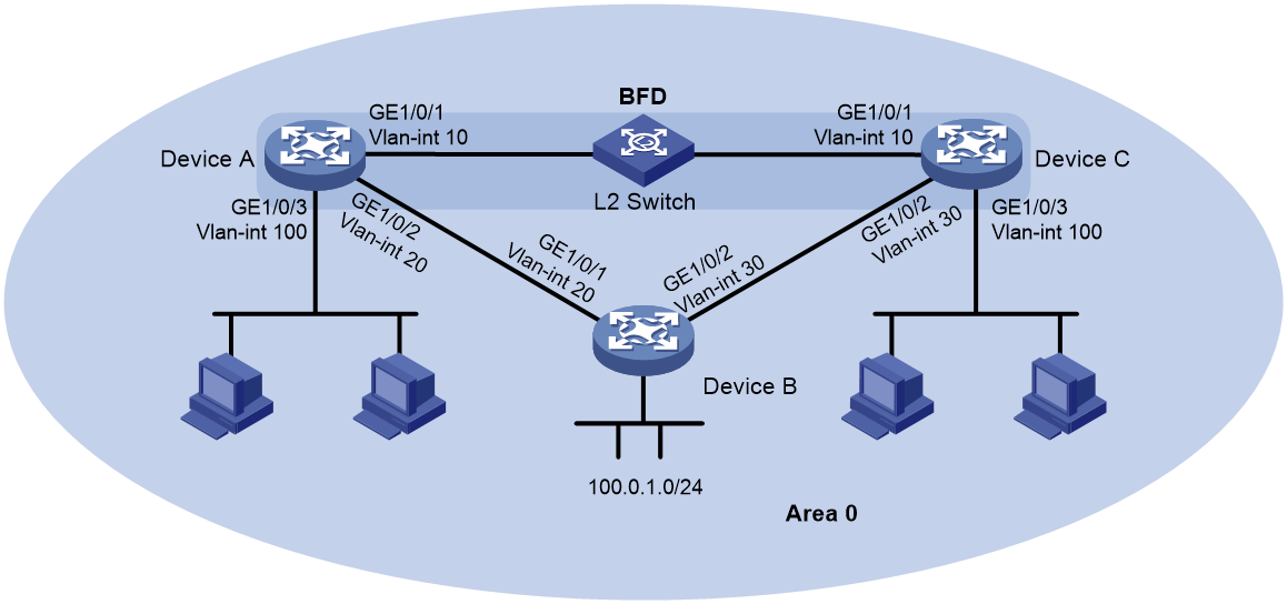
Table 3 Interface and IP address assignment
|
Device |
Interface |
IP address |
|
Device A |
Vlan-int10 |
10.1.0.101/24 |
|
Device A |
Vlan-int20 |
192.168.0.101/24 |
|
Device A |
Vlan-int100 |
120.1.1.1/24 |
|
Device B |
Vlan-int20 |
192.168.0.102/24 |
|
Device B |
Vlan-int30 |
13.1.1.101/24 |
|
Device C |
Vlan-int10 |
10.1.0.102/24 |
|
Device C |
Vlan-int30 |
13.1.1.102/24 |
|
Device C |
Vlan-int100 |
121.1.1.1/24 |
Applicable hardware and software versions
The following matrix shows the hardware and software versions to which this configuration example is applicable:
|
Hardware |
Software version |
|
S6812 switch series S6813 switch series |
Release 66xx |
|
S6550XE-HI switch series |
Release 6008 and later |
|
S6525XE-HI switch series |
Release 6008 and later |
|
S5850 switch series |
Release 8005 and later |
|
S5570S-EI switch series |
Release 11xx |
|
S5560X-EI switch series |
Release 63xx, Release 65xx, Release 66xx |
|
S5560X-HI switch series |
Release 63xx, Release 65xx, Release 66xx |
|
S5500V2-EI switch series |
Release 63xx, Release 65xx, Release 66xx |
|
MS4520V2-30F switch |
Release 63xx, Release 65xx, Release 66xx |
|
MS4520V2-30C switch MS4520V2-54C switch |
Release 65xx, Release 66xx |
|
MS4520V2-28S switch MS4520V2-24TP switch |
Release 63xx |
|
S6520X-HI switch series S6520X-EI switch series |
Release 63xx, Release 65xx |
|
S6520X-SI switch series S6520-SI switch series |
Release 63xx, Release 65xx, Release 66xx |
|
S5000-EI switch series |
Release 63xx, Release 65xx, Release 66xx |
|
MS4600 switch series |
Release 63xx, Release 65xx, Release 66xx |
|
ES5500 switch series |
Release 63xx, Release 65xx, Release 66xx |
|
S5560S-EI switch series S5560S-SI switch series |
Release 63xx |
|
S5500V3-24P-SI S5500V3-48P-SI |
Release 63xx |
|
S5500V3-SI switch series (excluding S5500V3-24P-SI and S5500V3-48P-SI) |
Release 11xx |
|
S5170-EI switch series |
Release 11xx |
|
S5130S-HI switch series S5130S-EI switch series S5130S-SI switch series S5130S-LI switch series |
Release 63xx |
|
S5120V2-SI switch series S5120V2-LI switch series |
Release 63xx |
|
S5120V3-EI switch series |
Release 11xx |
|
S5120V3-36F-SI S5120V3-28P-HPWR-SI S5120V3-54P-PWR-SI |
Release 11xx |
|
S5120V3-SI switch series (excluding S5120V3-36F-SI, S5120V3-28P-HPWR-SI, and S5120V3-54P-PWR-SI) |
Release 63xx |
|
S5120V3-LI switch series |
Release 63xx |
|
S3600V3-EI switch series |
Release 11xx |
|
S3600V3-SI switch series |
Not supported |
|
S3100V3-EI switch series S3100V3-SI switch series |
Release 63xx |
|
S5110V2 switch series |
Release 63xx |
|
S5110V2-SI switch series |
Not supported |
|
S5000V3-EI switch series S5000V5-EI switch series |
Not supported |
|
S5000E-X switch series S5000X-EI switch series |
Release 63xx |
|
E128C switch E152C switch E500C switch series E500D switch series |
Release 63xx |
|
MS4320V2 switch series MS4320V3 switch series MS4300V2 switch series MS4320 switch series MS4200 switch series |
Release 63xx |
|
WS5850-WiNet switch series |
Release 63xx |
|
WS5820-WiNet switch series WS5810-WiNet switch series |
Release 63xx |
|
WAS6000 switch series |
Release 63xx |
|
IE4300-12P-AC switch IE4300-12P-PWR switch IE4300-M switch series IE4320 switch series |
Release 63xx |
Restrictions and guidelines
In BFD control packet mode, a minimum of one end must operate in active mode for a BFD session to be established.
Procedures
Configuring interface IP addresses
1. Configure Device A:
<DeviceA> system-view
[DeviceA] vlan 10
[DeviceA-vlan10] port gigabitethernet 1/0/1
[DeviceA-vlan10] quit
[DeviceA] interface vlan-interface 10
[DeviceA-Vlan-interface10] ip address 10.1.0.101 24
[DeviceA-Vlan-interface10] quit
2. Configure other devices in the same way Device A is configured. (Details not shown.)
Configuring OSPF
1. Configure Device A:
# Configure basic OSPF functions, and enable BFD for OSPF.
[DeviceA] ospf
[DeviceA-ospf-1] area 0
[DeviceA-ospf-1-area-0.0.0.0] network 10.1.0.0 0.0.0.255
[DeviceA-ospf-1-area-0.0.0.0] network 192.168.0.0 0.0.0.255
[DeviceA-ospf-1-area-0.0.0.0] network 120.1.1.0 0.0.0.255
[DeviceA-ospf-1-area-0.0.0.0] quit
[DeviceA-ospf-1] quit
[DeviceA] interface vlan-interface 10
[DeviceA-Vlan-interface10] ospf bfd enable
[DeviceA-Vlan-interface10] quit
2. Configure Device B:
# Configure basic OSPF functions.
[DeviceB] ospf
[DeviceB-ospf-1] area 0
[DeviceB-ospf-1-area-0.0.0.0] network 192.168.0.0 0.0.0.255
[DeviceB-ospf-1-area-0.0.0.0] network 13.1.1.0 0.0.0.255
[DeviceB-ospf-1-area-0.0.0.0] quit
[DeviceB-ospf-1] quit
3. Configure Device C:
# Configure basic OSPF functions, and enable BFD for OSPF.
[DeviceC] ospf
[DeviceC-ospf-1] area 0
[DeviceC-ospf-1-area-0.0.0.0] network 10.1.0.0 0.0.0.255
[DeviceC-ospf-1-area-0.0.0.0] network 13.1.1.0 0.0.0.255
[DeviceC-ospf-1-area-0.0.0.0] network 121.1.1.0 0.0.0.255
[DeviceC-ospf-1-area-0.0.0.0] quit
[DeviceC-ospf-1] quit
[DeviceC] interface vlan-interface 10
[DeviceC-Vlan-interface10] ospf bfd enable
[DeviceC-Vlan-interface10] quit
Configuring BFD parameters
1. Configure Device A:
# Configure the session establishment mode as active (this is the default mode).
[DeviceA] bfd session init-mode active
# Configure the minimum interval for sending and receiving single-hop BFD control packets and the single-hop detection time multiplier.
[DeviceA] interface vlan-interface 10
[DeviceA-Vlan-interface10] bfd min-transmit-interval 100
[DeviceA-Vlan-interface10] bfd min-receive-interval 100
[DeviceA-Vlan-interface10] bfd detect-multiplier 3
[DeviceA-Vlan-interface10] quit
2. Configure Device C:
# Configure the session establishment mode as active (this is the default mode).
[DeviceC] bfd session init-mode active
# Configure the minimum interval for sending and receiving single-hop BFD control packets and the single-hop detection time multiplier.
[DeviceC] interface vlan-interface 10
[DeviceC-Vlan-interface10] bfd min-transmit-interval 100
[DeviceC-Vlan-interface10] bfd min-receive-interval 100
[DeviceC-Vlan-interface10] bfd detect-multiplier 3
[DeviceC-Vlan-interface10] quit
Verifying the configuration
# Ping host C (connected to Device C) from host A (connected to Device A) to verify the connectivity.
<host A> ping 121.1.1.2
PING 121.1.1.2 (121.1.1.2): 56 data bytes
56 bytes from 121.1.1.2: seq=0 ttl=128 time=22.43 ms
56 bytes from 121.1.1.2: seq=1 ttl=128 time=7.17 ms
56 bytes from 121.1.1.2: seq=2 ttl=128 time=8.91 ms
56 bytes from 121.1.1.2: seq=3 ttl=128 time=7.45 ms
56 bytes from 121.1.1.2: seq=4 ttl=128 time=9.11 ms
--- 121.1.1.2 ping statistics ---
5 packets transmitted, 5 packets received, 0% packet loss
round-trip min/avg/max/std-dev = 7.17/11.01/22.43 ms
The output shows that host C can be pinged successfully.
# Display detailed OSPF neighbor information on Device A.
[DeviceA] display ospf peer verbose
OSPF Process 1 with Router ID 2.2.2.2
Neighbors
Area 0.0.0.0 interface 10.1.0.101(Vlan-interface10)'s neighbors
Router ID: 1.1.1.1 Address: 10.1.0.102 GR State: Normal
State: Full Mode: Nbr is Slave Priority: 1
DR: 10.1.0.101 BDR: 10.1.0.102 MTU: 0
Options is 0x42 (-|O|-|-|-|-|E|-)
Dead timer due in 39 sec
Neighbor is up for 00:09:01
Authentication Sequence: [ 0 ]
Neighbor state change count: 5
BFD status: Enabled(Control mode)
The output shows that Device A has established OSPF neighbor relationship with Device C.
# Display BFD session information on Device A and Device C.
[DeviceA] display bfd session verbose
Total Session Num: 1 Up Session Num: 1 Init Mode: Active
IPv4 session working in control packet mode:
Local Discr: 2049 Remote Discr: 2049
Source IP: 10.1.0.101 Destination IP: 10.1.0.102
Session State: Up Interface: Vlan-interface10
Min Tx Inter: 100ms Act Tx Inter: 100ms
Min Rx Inter: 100ms Detect Inter: 300ms
Rx Count: 536 Tx Count: 536
Connect Type: Direct Running Up for: 00:04:48
Hold Time: 300ms Auth mode: None
Detect Mode: Async Slot: 1
Protocol: OSPF
Version: 1
Diag Info: No Diagnostic
[DeviceC] display bfd session verbose
Total Session Num: 1 Up Session Num: 1 Init Mode: Active
IPv4 session working in control packet mode:
Local Discr: 2049 Remote Discr: 2049
Source IP: 10.1.0.102 Destination IP: 10.1.0.101
Session State: Up Interface: Vlan-interface10
Min Tx Inter: 100ms Act Tx Inter: 100ms
Min Rx Inter: 100ms Detect Inter: 300ms
Rx Count: 3971 Tx Count: 3776
Connect Type: Direct Running Up for: 00:06:52
Hold Time: 300ms Auth mode: None
Detect Mode: Async Slot: 1
Protocol: OSPF
Version: 1
Diag Info: No Diagnostic
The output shows that BFD sessions have been established and are up.
# (Release 63xx) Display information about the routes to network 121.1.1.0/24 on Device A.
<DeviceA> display ip routing-table 121.1.1.0 verbose
Summary Count : 1
Destination: 121.1.1.0/24
Protocol: OSPF
Process ID: 1
SubProtID: 0x1 Age: 04h20m37s
Cost: 1 Preference: 10
IpPre: N/A QosLocalID: N/A
Tag: 0 State: Active Adv
OrigTblID: 0x0 OrigVrf: default-vrf
TableID: 0x2 OrigAs: 0
NibID: 0x26000002 LastAs: 0
AttrID: 0xffffffff Neighbor: 0.0.0.0
Flags: 0x1008c OrigNextHop: 10.1.0.102
Label: NULL RealNextHop: 10.1.0.102
BkLabel: NULL BkNextHop: N/A
SRLabel: NULL BkSRLabel: NULL
Tunnel ID: Invalid Interface: Vlan-interface10
BkTunnel ID: Invalid BkInterface: N/A
FtnIndex: 0x0 TrafficIndex: N/A
Connector: N/A PathID: 0x0
# (Release 65xx, 6008 and later, 8005 and later, 1106 and later, and 66xx) Display information about the routes to network 121.1.1.0/24 on Device A.
<DeviceA> display ip routing-table 121.1.1.0 verbose
Summary Count : 1
Destination: 121.1.1.0/24
Protocol: OSPF
Process ID: 1
SubProtID: 0x1 Age: 04h20m37s
Cost: 1 Preference: 10
IpPre: N/A QosLocalID: N/A
Tag: 0 State: Active Adv
OrigTblID: 0x0 OrigVrf: default-vrf
TableID: 0x2 OrigAs: 0
NibID: 0x26000002 LastAs: 0
AttrID: 0xffffffff Neighbor: 0.0.0.0
Flags: 0x1008c OrigNextHop: 10.1.0.102
Label: NULL RealNextHop: 10.1.0.102
BkLabel: NULL BkNextHop: N/A
SRLabel: NULL BkSRLabel: NULL
SIDIndex: NULL InLabel: NULL
Tunnel ID: Invalid Interface: Vlan-interface10
BkTunnel ID: Invalid BkInterface: N/A
FtnIndex: 0x0 TrafficIndex: N/A
Connector: N/A PathID: 0x0
LinkCost: 0 MicroSegID: 0
The output shows that Device A communicates with Device C through the Layer 2 switch.
# When the link between Device C and the Layer 2 switch fails, view BFD log information.
%Oct 9 15:22:23:154 2013 DeviceC BFD/5/BFD_CHANGE_FSM: Sess[10.1.0.102/10.1.0.101, LD/RD:2049/2049, Interface:Vlan10, SessType:Ctrl, LinkType:INET], Ver:1, Sta: UP-> DOWN, Diag: 1 (Control Detection Time Expired)
%Oct 9 15:22:23:155 2013 DeviceC OSPF/5/OSPF_NBR_CHG: OSPF 1 Neighbor 10.1.0.101(Vlan-interface10) from FULL to DOWN.
The output shows that BFD can quickly detect the failure and notify OSPF.
# (Release 63xx) Display information about the routes to network 121.1.1.0/24 on Device A.
<DeviceA> display ip routing-table 121.1.1.0 verbose
Summary Count : 1
Destination: 121.1.1.0/24
Protocol: OSPF
Process ID: 1
SubProtID: 0x1 Age: 04h20m37s
Cost: 2 Preference: 10
IpPre: N/A QosLocalID: N/A
Tag: 0 State: Active Adv
OrigTblID: 0x0 OrigVrf: default-vrf
TableID: 0x2 OrigAs: 0
NibID: 0x26000002 LastAs: 0
AttrID: 0xffffffff Neighbor: 0.0.0.0
Flags: 0x1008c OrigNextHop: 192.168.0.102
Label: NULL RealNextHop: 192.168.0.102
BkLabel: NULL BkNextHop: N/A
SRLabel: NULL BkSRLabel: NULL
Tunnel ID: Invalid Interface: Vlan-interface20
BkTunnel ID: Invalid BkInterface: N/A
FtnIndex: 0x0 TrafficIndex: N/A
Connector: N/A PathID: 0x0
# (Release 65xx, 6008 and later, and 8005 and later) Display information about the routes to network 121.1.1.0/24 on Device A.
<DeviceA> display ip routing-table 121.1.1.0 verbose
Summary Count : 1
Destination: 121.1.1.0/24
Protocol: OSPF
Process ID: 1
SubProtID: 0x1 Age: 04h20m37s
Cost: 2 Preference: 10
IpPre: N/A QosLocalID: N/A
Tag: 0 State: Active Adv
OrigTblID: 0x0 OrigVrf: default-vrf
TableID: 0x2 OrigAs: 0
NibID: 0x26000002 LastAs: 0
AttrID: 0xffffffff Neighbor: 0.0.0.0
Flags: 0x1008c OrigNextHop: 192.168.0.102
Label: NULL RealNextHop: 192.168.0.102
BkLabel: NULL BkNextHop: N/A
SRLabel: NULL BkSRLabel: NULL
SIDIndex: NULL InLabel: NULL
Tunnel ID: Invalid Interface: Vlan-interface20
BkTunnel ID: Invalid BkInterface: N/A
FtnIndex: 0x0 TrafficIndex: N/A
Connector: N/A PathID: 0x0
LinkCost: 0 MicroSegID: 0
The output shows that Device A communicates with Device C through Device B.
Configuration files
|
|
NOTE: Support for the port link-mode bridge command depends on the device model. |
· Device A:
#
ospf 1
area 0.0.0.0
network 10.1.0.0 0.0.0.255
network 120.1.1.0 0.0.0.255
network 192.168.0.0 0.0.0.255
#
vlan 10
#
vlan 20
#
vlan 100
#
interface Vlan-interface10
ip address 10.1.0.101 255.255.255.0
ospf bfd enable
bfd min-transmit-interval 100
bfd min-receive-interval 100
bfd detect-multiplier 3
#
interface Vlan-interface20
ip address 192.168.0.101 255.255.255.0
#
interface Vlan-interface100
ip address 120.1.1.1 255.255.255.0
#
interface GigabitEthernet1/0/1
port link-mode bridge
port access vlan 10
#
interface GigabitEthernet1/0/2
port link-mode bridge
port access vlan 20
#
interface GigabitEthernet1/0/3
port link-mode bridge
port access vlan 100
#
· Device B:
#
ospf 1
area 0.0.0.0
network 13.1.1.0 0.0.0.255
network 192.168.0.0 0.0.0.255
#
vlan 20
#
vlan 30
#
interface Vlan-interface20
ip address 192.168.0.102 255.255.255.0
#
interface Vlan-interface30
ip address 13.1.1.101 255.255.255.0
#
interface GigabitEthernet1/0/1
port link-mode bridge
port access vlan 20
#
interface GigabitEthernet1/0/2
port link-mode bridge
port access vlan 30
#
· Device C:
#
ospf 1
area 0.0.0.0
network 10.1.0.0 0.0.0.255
network 13.1.1.0 0.0.0.255
network 121.1.1.0 0.0.0.255
#
vlan 10
#
vlan 30
#
vlan 100
#
interface Vlan-interface10
ip address 10.1.0.102 255.255.255.0
ospf bfd enable
bfd min-transmit-interval 100
bfd min-receive-interval 100
bfd detect-multiplier 3
#
interface Vlan-interface30
ip address 13.1.1.102 255.255.255.0
#
interface Vlan-interface100
ip address 121.1.1.1 255.255.255.0
#
interface GigabitEthernet1/0/1
port link-mode bridge
port access vlan 10
#
interface GigabitEthernet1/0/2
port link-mode bridge
port access vlan 30
#
interface GigabitEthernet1/0/3
port link-mode bridge
port access vlan 100
#
Example: Configuring BFD for IS-IS
Network configuration
As shown in Figure 5, Device A, Device B, and Device C run IS-IS. Device A and Device C are connected through a Layer 2 switch.
Enable BFD control packet mode on Device A and Device C to monitor the path over the Layer 2 switch. When BFD detects a link failure, it notifies IS-IS to switch to the path over Device B.
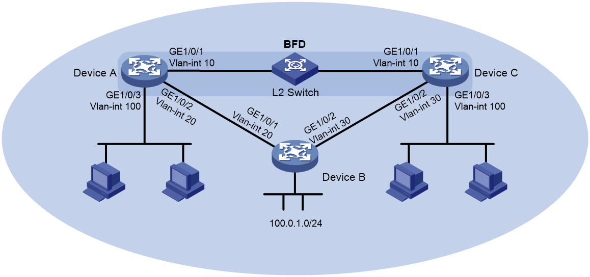
Table 4 Interface and IP address assignment
|
Device |
Interface |
IP address |
|
Device A |
Vlan-int10 |
10.1.0.101/24 |
|
Device A |
Vlan-int20 |
192.168.0.101/24 |
|
Device A |
Vlan-int100 |
120.1.1.1/24 |
|
Device B |
Vlan-int20 |
192.168.0.102/24 |
|
Device B |
Vlan-int30 |
13.1.1.101/24 |
|
Device C |
Vlan-int10 |
10.1.0.102/24 |
|
Device C |
Vlan-int30 |
13.1.1.102/24 |
|
Device C |
Vlan-int100 |
121.1.1.1/24 |
Applicable hardware and software versions
The following matrix shows the hardware and software versions to which this configuration example is applicable:
|
Hardware |
Software version |
|
S6812 switch series S6813 switch series |
Release 66xx |
|
S6550XE-HI switch series |
Release 6008 and later |
|
S6525XE-HI switch series |
Release 6008 and later |
|
S5850 switch series |
Release 8005 and later |
|
S5570S-EI switch series |
Release 11xx |
|
S5560X-EI switch series |
Release 63xx, Release 65xx, Release 66xx |
|
S5560X-HI switch series |
Release 63xx, Release 65xx, Release 66xx |
|
S5500V2-EI switch series |
Release 63xx, Release 65xx, Release 66xx |
|
MS4520V2-30F switch |
Release 63xx, Release 65xx, Release 66xx |
|
MS4520V2-30C switch MS4520V2-54C switch |
Release 65xx, Release 66xx |
|
MS4520V2-28S switch MS4520V2-24TP switch |
Release 63xx |
|
S6520X-HI switch series S6520X-EI switch series |
Release 63xx, Release 65xx, Release 66xx |
|
S6520X-SI switch series S6520-SI switch series |
Release 63xx, Release 65xx, Release 66xx |
|
S5000-EI switch series |
Release 63xx, Release 65xx, Release 66xx |
|
MS4600 switch series |
Release 63xx, Release 65xx, Release 66xx |
|
ES5500 switch series |
Release 63xx, Release 65xx, Release 66xx |
|
S5560S-EI switch series S5560S-SI switch series |
Release 63xx |
|
S5500V3-24P-SI S5500V3-48P-SI |
Release 63xx |
|
S5500V3-SI switch series (excluding S5500V3-24P-SI and S5500V3-48P-SI) |
Release 11xx |
|
S5170-EI switch series |
Not supported |
|
S5130S-HI switch series S5130S-EI switch series S5130S-SI switch series S5130S-LI switch series |
Not supported |
|
S5120V2-SI switch series S5120V2-LI switch series |
Not supported |
|
S5120V3-EI switch series |
Not supported |
|
S5120V3-36F-SI S5120V3-28P-HPWR-SI S5120V3-54P-PWR-SI |
Not supported |
|
S5120V3-SI switch series (excluding S5120V3-36F-SI, S5120V3-28P-HPWR-SI, and S5120V3-54P-PWR-SI) |
Not supported |
|
S5120V3-LI switch series |
Not supported |
|
S3600V3-EI switch series |
Release 11xx |
|
S3600V3-SI switch series |
Not supported |
|
S3100V3-EI switch series S3100V3-SI switch series |
Not supported |
|
S5110V2 switch series |
Not supported |
|
S5110V2-SI switch series |
Not supported |
|
S5000V3-EI switch series S5000V5-EI switch series |
Not supported |
|
S5000E-X switch series S5000X-EI switch series |
Not supported |
|
E128C switch E152C switch E500C switch series E500D switch series |
Not supported |
|
MS4320V2 switch series MS4320V3 switch series MS4300V2 switch series MS4320 switch series MS4200 switch series |
Not supported |
|
WS5850-WiNet switch series |
Release 63xx |
|
WS5820-WiNet switch series WS5810-WiNet switch series |
Not supported |
|
WAS6000 switch series |
Not supported |
|
IE4300-12P-AC switch IE4300-12P-PWR switch IE4300-M switch series IE4320 switch series |
Not supported |
Restrictions and guidelines
In BFD control packet mode, a minimum of one end must operate in active mode for a BFD session to be established.
Procedures
Configuring interface IP addresses
1. Configure Device A:
<DeviceA> system-view
[DeviceA] vlan 10
[DeviceA-vlan10] port gigabitethernet 1/0/1
[DeviceA-vlan10] quit
[DeviceA] interface vlan-interface 10
[DeviceA-Vlan-interface10] ip address 10.1.0.101 24
[DeviceA-Vlan-interface10] quit
2. Configure other devices in the same way Device A is configured. (Details not shown.)
Configuring IS-IS
1. Configure Device A:
# Configure basic IS-IS functions, and enable BFD for IS-IS.
[DeviceA] isis
[DeviceA-isis-1] network-entity 10.0000.0000.0001.00
[DeviceA-isis-1] quit
[DeviceA] interface vlan-interface 20
[DeviceA-Vlan-interface20] isis enable
[DeviceA-Vlan-interface20] quit
[DeviceA] interface vlan-interface 10
[DeviceA-Vlan-interface10] isis enable
[DeviceA-Vlan-interface10] isis bfd enable
[DeviceA-Vlan-interface10] quit
[DeviceA] interface vlan-interface 100
[DeviceA-Vlan-interface100] isis enable
[DeviceA-Vlan-interface100] isis bfd enable
[DeviceA-Vlan-interface100] quit
2. Configure Device B:
# Configure basic IS-IS functions.
[DeviceB] isis
[DeviceB-isis-1] network-entity 10.0000.0000.0003.00
[DeviceB-isis-1] quit
[DeviceB] interface vlan-interface 20
[DeviceB-Vlan-interface20] isis enable
[DeviceB-Vlan-interface20] quit
[DeviceB] interface vlan-interface 30
[DeviceB-Vlan-interface30] isis enable
[DeviceB-Vlan-interface30] quit
3. Configure Device C:
# Configure basic IS-IS functions, and enable BFD for IS-IS.
[DeviceC] isis
[DeviceC-isis-1] network-entity 10.0000.0000.0002.00
[DeviceC-isis-1] quit
[DeviceC] interface vlan-interface 10
[DeviceC-Vlan-interface10] isis enable
[DeviceC-Vlan-interface10] isis bfd enable
[DeviceC-Vlan-interface10] quit
[DeviceC] interface vlan 30
[DeviceC-Vlan-interface30] isis enable
[DeviceC-Vlan-interface30] quit
[DeviceC] interface vlan-interface 100
[DeviceC-Vlan-interface100] isis enable
[DeviceC-Vlan-interface100] isis bfd enable
[DeviceC-Vlan-interface100] quit
Configuring BFD parameters
1. Configure Device A:
# Configure the session establishment mode as active (this is the default mode).
[DeviceA] bfd session init-mode active
# Configure the minimum interval for sending and receiving single-hop BFD control packets and the single-hop detection time multiplier.
[DeviceA] interface vlan-interface 10
[DeviceA-Vlan-interface10] bfd min-transmit-interval 100
[DeviceA-Vlan-interface10] bfd min-receive-interval 100
[DeviceA-Vlan-interface10] bfd detect-multiplier 3
[DeviceA-Vlan-interface10] quit
2. Configure Device C:
# Configure the session establishment mode as active (this is the default mode).
[DeviceC] bfd session init-mode active
# Configure the minimum interval for sending and receiving single-hop BFD control packets and the single-hop detection time multiplier.
[DeviceC] interface vlan 10
[DeviceC-Vlan-interface10] bfd min-transmit-interval 100
[DeviceC-Vlan-interface10] bfd min-receive-interval 100
[DeviceC-Vlan-interface10] bfd detect-multiplier 3
[DeviceC-Vlan-interface10] quit
Verifying the configuration
# Display detailed IS-IS neighbor information on Device A.
[DeviceA] display isis peer verbose
Peer information for IS-IS(1)
-----------------------------
System ID: 0000.0000.0002
Interface: Vlan10 Circuit Id: 0000.0000.0002.01
State: Up HoldTime: 6s Type: L1(L1L2) PRI: 64
Area address(es): 00
Peer IP address(es): 10.1.0.102
Peer local circuit ID: 1
Peer circuit SNPA address: ce9d-d91d-d100
Uptime: 00:01:19
Adj protocol: IPv4
Graceful Restart capable
Restarting signal: No
Suppress adjacency advertisement: No
Local topology:
0
Remote topology:
0
The output shows that Device A has established IS-IS neighbor relationship with Device C.
# Display BFD session information on Device A and Device C.
[DeviceA] display bfd session verbose
Total Session Num: 1 Up Session Num: 1 Init Mode: Active
IPv4 session working in control packet mode:
Local Discr: 2049 Remote Discr: 2049
Source IP: 10.1.0.101 Destination IP: 10.1.0.102
Session State: Up Interface: Vlan-interface10
Min Tx Inter: 100ms Act Tx Inter: 100ms
Min Rx Inter: 100ms Detect Inter: 300ms
Rx Count: 3 Tx Count: 3
Connect Type: Direct Running Up for: 00:06:09
Hold Time: 300ms Auth mode: None
Detect Mode: Async Slot: 1
Protocol: ISIS_BR_L1/ISIS_BR_L2
Version: 1
Diag Info: No Diagnostic
[DeviceC] display bfd session verbose
Total Session Num: 1 Up Session Num: 1 Init Mode: Active
IPv4 session working in control packet mode:
Local Discr: 2049 Remote Discr: 2049
Source IP: 10.1.0.102 Destination IP: 10.1.0.101
Session State: Up Interface: Vlan-interface10
Min Tx Inter: 100ms Act Tx Inter: 100ms
Min Rx Inter: 100ms Detect Inter: 300ms
Rx Count: 3 Tx Count: 3
Connect Type: Direct Running Up for: 00:07:10
Hold Time: 300ms Auth mode: None
Detect Mode: Async Slot: 1
Protocol: ISIS_BR_L1/ISIS_BR_L2
Version: 1
Diag Info: No Diagnostic
The output shows that BFD sessions have been established and are up.
# (Release 63xx) Display information about the routes to network 121.1.1.0/24 on Device A.
<DeviceA> display ip routing-table 121.1.1.0 verbose
Summary Count : 1
Destination: 121.1.1.0/24
Protocol: IS_L1
Process ID: 1
SubProtID: 0x1 Age: 04h20m37s
Cost: 20 Preference: 15
IpPre: N/A QosLocalID: N/A
Tag: 0 State: Active Adv
OrigTblID: 0x2 OrigVrf: default-vrf
TableID: 0x2 OrigAs: 0
NibID: 0x26000002 LastAs: 0
AttrID: 0xffffffff Neighbor: 0.0.0.0
Flags: 0x1008c OrigNextHop: 10.1.0.102
Label: NULL RealNextHop: 10.1.0.102
BkLabel: NULL BkNextHop: N/A
SRLabel: NULL BkSRLabel: NULL
Tunnel ID: Invalid Interface: Vlan-interface10
BkTunnel ID: Invalid BkInterface: N/A
FtnIndex: 0x0 TrafficIndex: N/A
Connector: N/A PathID: 0x0
# (Release 65xx, 6008 and later, and 8005 and later) Display information about the routes to network 121.1.1.0/24 on Device A.
<DeviceA> display ip routing-table 121.1.1.0 verbose
Summary Count : 1
Destination: 121.1.1.0/24
Protocol: IS_L1
Process ID: 1
SubProtID: 0x1 Age: 04h20m37s
Cost: 20 Preference: 15
IpPre: N/A QosLocalID: N/A
Tag: 0 State: Active Adv
OrigTblID: 0x2 OrigVrf: default-vrf
TableID: 0x2 OrigAs: 0
NibID: 0x26000002 LastAs: 0
AttrID: 0xffffffff Neighbor: 0.0.0.0
Flags: 0x1008c OrigNextHop: 10.1.0.102
Label: NULL RealNextHop: 10.1.0.102
BkLabel: NULL BkNextHop: N/A
SRLabel: NULL BkSRLabel: NULL
SIDIndex: NULL InLabel: NULL
Tunnel ID: Invalid Interface: Vlan-interface10
BkTunnel ID: Invalid BkInterface: N/A
FtnIndex: 0x0 TrafficIndex: N/A
Connector: N/A PathID: 0x0
LinkCost: 0 MicroSegID: 0
The output shows that Device A communicates with Device C through the Layer 2 switch.
# When the link between Device C and the Layer 2 switch fails, view BFD log information.
%Oct 9 16:11:24:163 2013 DeviceC BFD/5/BFD_CHANGE_FSM: Sess[10.1.0.102/10.1.0.101, LD/RD:2049/2049, Interface:Vlan10, SessType:Ctrl, LinkType:INET], Ver:1, Sta: UP-> DOWN, Diag: 1 (Control Detection Time Expired)
%Oct 9 16:11:24:164 2013 DeviceC ISIS/5/ISIS_NBR_CHG: IS-IS 1, Level-1 adjacency 0000.0000.0001 (Vlan-interface10), state changed to DOWN, Reason: BFD session down.
%Oct 9 16:11:24:164 2013 DeviceC ISIS/5/ISIS_NBR_CHG: IS-IS 1, Level-2 adjacency 0000.0000.0001 (Vlan-interface10), state changed to DOWN, Reason: BFD session down.
The output shows that BFD can quickly detect the failure and notify IS-IS.
# (Release 63xx) Display information about the routes to network 121.1.1.0/24 on Device A.
<DeviceA> display ip routing-table 121.1.1.0 verbose
Summary Count : 1
Destination: 121.1.1.0/24
Protocol: IS_L1
Process ID: 1
SubProtID: 0x1 Age: 04h20m37s
Cost: 2 Preference: 10
IpPre: N/A QosLocalID: N/A
Tag: 0 State: Active Adv
OrigTblID: 0x0 OrigVrf: default-vrf
TableID: 0x2 OrigAs: 0
NibID: 0x26000002 LastAs: 0
AttrID: 0xffffffff Neighbor: 0.0.0.0
Flags: 0x1008c OrigNextHop: 192.168.0.102
Label: NULL RealNextHop: 192.168.0.102
BkLabel: NULL BkNextHop: N/A
SRLabel: NULL BkSRLabel: NULL
Tunnel ID: Invalid Interface: Vlan-interface20
BkTunnel ID: Invalid BkInterface: N/A
FtnIndex: 0x0 TrafficIndex: N/A
Connector: N/A PathID: 0x0
# (Release 65xx, 6008 and later, and 8005 and later) Display information about the routes to network 121.1.1.0/24 on Device A.
<DeviceA> display ip routing-table 121.1.1.0 verbose
Summary Count : 1
Destination: 121.1.1.0/24
Protocol: IS_L1
Process ID: 1
SubProtID: 0x1 Age: 04h20m37s
Cost: 2 Preference: 10
IpPre: N/A QosLocalID: N/A
Tag: 0 State: Active Adv
OrigTblID: 0x0 OrigVrf: default-vrf
TableID: 0x2 OrigAs: 0
NibID: 0x26000002 LastAs: 0
AttrID: 0xffffffff Neighbor: 0.0.0.0
Flags: 0x1008c OrigNextHop: 192.168.0.102
Label: NULL RealNextHop: 192.168.0.102
BkLabel: NULL BkNextHop: N/A
SRLabel: NULL BkSRLabel: NULL
SIDIndex: NULL InLabel: NULL
Tunnel ID: Invalid Interface: Vlan-interface20
BkTunnel ID: Invalid BkInterface: N/A
FtnIndex: 0x0 TrafficIndex: N/A
Connector: N/A PathID: 0x0
LinkCost: 0 MicroSegID: 0
The output shows that Device A communicates with Device C through Device B.
Configuration files
|
|
NOTE: Support for the port link-mode bridge command depends on the device model. |
· Device A:
#
isis 1
network-entity 10.0000.0000.0001.00
#
vlan 10
#
vlan 20
#
vlan 100
#
interface Vlan-interface10
ip address 10.1.0.101 255.255.255.0
isis enable 1
isis bfd enable
bfd min-transmit-interval 100
bfd min-receive-interval 100
bfd detect-multiplier 3
#
interface Vlan-interface20
ip address 192.168.0.101 255.255.255.0
isis enable 1
#
interface Vlan-interface100
ip address 120.1.1.1 255.255.255.0
isis enable 1
#
interface GigabitEthernet1/0/1
port link-mode bridge
port access vlan 10
#
interface GigabitEthernet1/0/2
port link-mode bridge
port access vlan 20
#
interface GigabitEthernet1/0/3
port link-mode bridge
port access vlan 100
#
· Device B:
#
isis 1
network-entity 10.0000.0000.0003.00
#
vlan 20
#
vlan 30
#
interface Vlan-interface20
ip address 192.168.0.102 255.255.255.0
isis enable 1
#
interface Vlan-interface30
ip address 13.1.1.101 255.255.255.0
isis enable 1
#
interface GigabitEthernet1/0/1
port link-mode bridge
port access vlan 20
#
interface GigabitEthernet1/0/2
port link-mode bridge
port access vlan 30
#
· Device C:
#
isis 1
network-entity 10.0000.0000.0002.00
#
vlan 10
#
vlan 30
#
vlan 100
#
interface Vlan-interface10
ip address 10.1.0.102 255.255.255.0
isis enable 1
isis bfd enable
bfd min-transmit-interval 100
bfd min-receive-interval 100
bfd detect-multiplier 3
#
interface Vlan-interface30
ip address 13.1.1.102 255.255.255.0
isis enable 1
#
interface Vlan-interface100
ip address 121.1.1.1 255.255.255.0
isis enable 1
#
interface GigabitEthernet1/0/1
port link-mode bridge
port access vlan 10
#
interface GigabitEthernet1/0/2
port link-mode bridge
port access vlan 30
#
interface GigabitEthernet1/0/3
port link-mode bridge
port access vlan 100
#
Example: Configuring BFD for BGP
Network configuration
As shown in Figure 6, the devices in AS 100 run OSPF to reach each other. There are two paths between Device B and Device D:
· Path A—Path over Device C.
· Path B—Path over Device E.
When both paths are available, BGP uses the path over Device C to forward traffic between Device A and Device F.
Enable BFD control packet mode on Device B and Device D to monitor the path over Device C. When BFD detects a link failure, it notifies BGP to switch to the path over Device E.
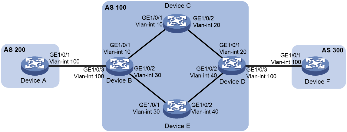
Table 5 Interface and IP address assignment
|
Device |
Interface |
IP address |
|
Device A |
Vlan-int100 |
120.1.0.1/24 |
|
Device B |
Vlan-int10 |
10.1.0.101/24 |
|
Device B |
Vlan-int30 |
192.168.0.101/24 |
|
Device B |
Vlan-int100 |
120.1.0.2/24 |
|
Device C |
Vlan-int10 |
10.1.0.102/24 |
|
Device C |
Vlan-int20 |
10.2.0.102/24 |
|
Device D |
Vlan-int20 |
10.2.0.101/24 |
|
Device D |
Vlan-int40 |
13.1.1.101/24 |
|
Device D |
Vlan-int100 |
120.2.0.2/24 |
|
Device E |
Vlan-int30 |
192.168.0.102/24 |
|
Device E |
Vlan-int40 |
13.1.1.102/24 |
|
Device F |
Vlan-int100 |
120.2.0.1/24 |
Analysis
For Path A to become the primary path, use a routing policy to set a lower cost for Path A than Path B.
Applicable hardware and software versions
The following matrix shows the hardware and software versions to which this configuration example is applicable:
|
Hardware |
Software version |
|
S6550XE-HI switch series |
Release 6008 and later |
|
S6525XE-HI switch series |
Release 6008 and later |
|
S5850 switch series |
Release 8005 and later |
|
S5560X-EI switch series |
Release 63xx, Release 65xx |
|
S5560X-HI switch series |
Release 63xx, Release 65xx |
|
S5500V2-EI switch series |
Release 63xx, Release 65xx |
|
MS4520V2-30F switch |
Release 63xx, Release 65xx |
|
MS4520V2-30C switch MS4520V2-54C switch |
Release 65xx |
|
MS4520V2-28S switch MS4520V2-24TP switch |
Release 63xx |
|
S6520X-HI switch series S6520X-EI switch series |
Release 63xx, Release 65xx |
|
S6520X-SI switch series S6520-SI switch series |
Release 63xx, Release 65xx |
|
S5000-EI switch series |
Release 63xx, Release 65xx |
|
MS4600 switch series |
Release 63xx, Release 65xx |
|
ES5500 switch series |
Release 63xx, Release 65xx |
|
S5560S-EI switch series S5560S-SI switch series |
Release 63xx |
|
S5130S-HI switch series S5130S-EI switch series S5130S-SI switch series S5130S-LI switch series |
Not supported |
|
S5120V2-SI switch series S5120V2-LI switch series |
Not supported |
|
S3100V3-EI switch series S3100V3-SI switch series |
Not supported |
|
S5110V2 switch series |
Not supported |
|
S5110V2-SI switch series |
Not supported |
|
S5000V3-EI switch series S5000V5-EI switch series |
Not supported |
|
S5000E-X switch series |
Not supported |
|
E128C switch E152C switch |
Release 63xx |
|
E500C switch series E500D switch series |
Not supported |
|
MS4320V2 switch series MS4300V2 switch series MS4320 switch series MS4200 switch series |
Not supported |
|
WS5850-WiNet switch series |
Release 63xx |
|
WS5820-WiNet switch series WS5810-WiNet switch series |
Not supported |
|
WAS6000 switch series |
Release 63xx |
|
IE4300-12P-AC switch IE4300-12P-PWR switch IE4300-M switch series IE4320 switch series |
Not supported |
Restrictions and guidelines
In BFD control packet mode, a minimum of one end must operate in active mode for a BFD session to be established.
Procedures
Configuring interface IP addresses
# Configure IP addresses for the interfaces on the devices. (Details not shown.)
Configuring OSPF in AS 100
1. Configure Device B:
[DeviceB] ospf
[DeviceB-ospf-1] import-route direct
[DeviceB-ospf-1] area 0
[DeviceB-ospf-1-area-0.0.0.0] network 10.1.0.0 0.0.0.255
[DeviceB-ospf-1-area-0.0.0.0] network 192.168.0.0 0.0.0.255
[DeviceB-ospf-1-area-0.0.0.0] quit
[DeviceB-ospf-1] quit
2. Configure Device C:
[DeviceC] ospf
[DeviceC-ospf-1] area 0
[DeviceC-ospf-1-area-0.0.0.0] network 10.1.0.0 0.0.0.255
[DeviceC-ospf-1-area-0.0.0.0] network 10.2.0.0 0.0.0.255
[DeviceC-ospf-1-area-0.0.0.0] quit
[DeviceC-ospf-1] quit
3. Configure Device D:
[DeviceD] ospf
[DeviceD-ospf-1] import-route direct
[DeviceD-ospf-1] area 0
[DeviceD-ospf-1-area-0.0.0.0] network 10.2.0.0 0.0.0.255
[DeviceD-ospf-1-area-0.0.0.0] network 13.1.1.0 0.0.0.255
[DeviceD-ospf-1-area-0.0.0.0] quit
[DeviceD-ospf-1] quit
4. Configure Device E:
[DeviceE] ospf
[DeviceE-ospf-1] area 0
[DeviceE-ospf-1-area-0.0.0.0] network 13.1.1.0 0.0.0.255
[DeviceE-ospf-1-area-0.0.0.0] network 192.168.0.0 0.0.0.255
[DeviceE-ospf-1-area-0.0.0.0] quit
[DeviceE-ospf-1] quit
Configuring BGP
1. Configure Device A:
# Enable BGP and set the local AS number to 200.
[DeviceA] bgp 200
[DeviceA-bgp-default] router-id 1.1.1.1
# Establish an EBGP connection with Device B.
[DeviceA-bgp-default] peer 120.1.0.2 as-number 100
# Create the BGP IPv4 unicast address family and enter its view.
[DeviceA-bgp-default] address-family ipv4 unicast
# In BGP IPv4 unicast address family view, inject local network 120.1.0.0/24 to the BGP routing table.
[DeviceA-bgp-default-ipv4] network 120.1.0.0 255.255.255.0
# Enable BGP to exchange IPv4 unicast routing information with peer 120.1.0.2.
[DeviceA-bgp-default-ipv4] peer 120.1.0.2 enable
[DeviceA-bgp-default-ipv4] quit
2. Configure Device B:
# Enable BGP and set the local AS number to 100.
[DeviceB] bgp 100
[DeviceB-bgp-default] router-id 2.2.2.2
# Establish an EBGP connection with Device A.
[DeviceB-bgp-default] peer 120.1.0.1 as-number 200
# Establish IBGP connections with Device D.
[DeviceB-bgp-default] peer 10.2.0.101 as-number 100
[DeviceB-bgp-default] peer 13.1.1.101 as-number 100
# Create the BGP IPv4 unicast address family and enter its view.
[DeviceB-bgp-default] address-family ipv4 unicast
# Enable BGP to exchange IPv4 unicast routing information with peer 10.2.0.101.
[DeviceB-bgp-default-ipv4] peer 10.2.0.101 enable
# In BGP IPv4 unicast address family view, specify the device as the next hop for routes sent to peer 10.2.0.101.
[DeviceB-bgp-default-ipv4] peer 10.2.0.101 next-hop-local
# Enable BGP to exchange IPv4 unicast routing information with peer 13.1.1.101.
[DeviceB-bgp-default-ipv4] peer 13.1.1.101 enable
# In BGP IPv4 unicast address family view, specify the device as the next hop for routes sent to peer 13.1.1.101.
[DeviceB-bgp-default-ipv4] peer 13.1.1.101 next-hop-local
# Enable BGP to exchange IPv4 unicast routing information with peer 120.1.0.1.
[DeviceB-bgp-default-ipv4] peer 120.1.0.1 enable
[DeviceB-bgp-default-ipv4] quit
3. Configure Device D:
# Enable BGP and set the local AS number to 100.
[DeviceD] bgp 100
[DeviceD-bgp-default] router-id 4.4.4.4
# Establish IBGP connections with Device B.
[DeviceD-bgp-default] peer 10.1.0.101 as-number 100
[DeviceD-bgp-default] peer 192.168.0.101 as-number 100
# Establish an EBGP connection with Device F.
[DeviceD-bgp-default] peer 120.2.0.1 as-number 300
# Create the BGP IPv4 unicast address family and enter its view.
[DeviceD-bgp-default] address-family ipv4 unicast
# Enable BGP to exchange IPv4 unicast routing information with peer 10.1.0.101.
[DeviceD-bgp-default-ipv4] peer 10.1.0.101 enable
# In BGP IPv4 unicast address family view, specify the device as the next hop for routes sent to peer 10.1.0.101.
[DeviceD-bgp-default-ipv4] peer 10.1.0.101 next-hop-local
# Enable BGP to exchange IPv4 unicast routing information with peer 192.168.0.101.
[DeviceD-bgp-default-ipv4] peer 192.168.0.101 enable
# In BGP IPv4 unicast address family view, specify the device as the next hop for routes sent to peer 192.168.0.101.
[DeviceD-bgp-default-ipv4] peer 192.168.0.101 next-hop-local
# Enable BGP to exchange IPv4 unicast routing information with peer 120.2.0.1.
[DeviceD-bgp-default-ipv4] peer 120.2.0.1 enable
[DeviceD-bgp-default-ipv4] quit
4. Configure Device F:
# Enable BGP and set the local AS number to 300.
[DeviceF] bgp 300
[DeviceF-bgp-default] router-id 6.6.6.6
# Establish an EBGP connection with Device D.
[DeviceF-bgp-default] peer 120.2.0.2 as-number 100
# Create the BGP IPv4 unicast address family and enter its view.
[DeviceF-bgp-default] address-family ipv4 unicast
# In BGP IPv4 unicast address family view, inject local network 120.2.0.0/24 to the BGP routing table.
[DeviceF-bgp-default-ipv4] network 120.2.0.0 255.255.255.0
# Enable BGP to exchange IPv4 unicast routing information with peer 120.2.0.2.
[DeviceF-bgp-default-ipv4] peer 120.2.0.2 enable
[DeviceF-bgp-default-ipv4] quit
Configuring routing policies
1. Configure Device B:
# Create ACL 2000 to permit packets sourced from 120.1.0.0/24.
[DeviceB] acl basic 2000
[DeviceB-acl-ipv4-basic-2000] rule permit source 120.1.0.0 0.0.0.255
[DeviceB-acl-ipv4-basic-2000] quit
# Set a local preference of 200 for routes advertised to peer 10.2.0.101, and set the preference for IBGP routes to 100.
[DeviceB] route-policy local-pre permit node 10
[DeviceB-route-policy-local-pre] if-match ip address acl 2000
[DeviceB-route-policy-local-pre] apply local-preference 200
[DeviceB-route-policy-local-pre] quit
[DeviceB] bgp 100
[DeviceB-bgp-default] address-family ipv4 unicast
[DeviceB-bgp-default-ipv4] peer 10.2.0.101 route-policy local-pre export
[DeviceB-bgp-default-ipv4] preference 255 100 130
[DeviceB-bgp-default-ipv4] quit
2. Configure Device D:
# Create ACL 2000 to permit packets sourced from 120.2.0.0/24.
[DeviceD] acl basic 2000
[DeviceD-acl-ipv4-basic-2000] rule permit source 120.2.0.0 0.0.0.255
[DeviceD-acl-ipv4-basic-2000] quit
# Set a local preference of 200 for routes learned from peer 10.1.0.101, and configure the preference for IBGP routes as 100.
[DeviceD] route-policy local-pre permit node 10
[DeviceD-route-policy-local-pre] if-match ip address acl 2000
[DeviceD-route-policy-local-pre] apply local-preference 200
[DeviceD-route-policy-local-pre] quit
[DeviceD] bgp 100
[DeviceD-bgp-default] address-family ipv4 unicast
[DeviceD-bgp-default-ipv4] peer 10.1.0.101 route-policy local-pre export
[DeviceD-bgp-default-ipv4] preference 255 100 130
[DeviceD-bgp-default-ipv4] quit
Configuring BFD
1. Configure Device B:
# Enable BFD for the link to BGP peer 10.2.0.101.
[DeviceB] bgp 100
[DeviceB-bgp-default] peer 10.2.0.101 bfd
[DeviceB-bgp-default] quit
2. Configure Device D:
# Enable BFD for the link to BGP peer 10.1.0.101.
[DeviceD] bgp 100
[DeviceD-bgp-default] peer 10.1.0.101 bfd
[DeviceD-bgp-default] quit
Verifying the configuration
# Ping Device F from Device A to verify the connectivity.
[DeviceA] ping 120.2.0.1
Ping 120.2.0.1 (120.2.0.1): 56 data bytes, press CTRL+C to break
56 bytes from 120.2.0.1: icmp_seq=0 ttl=252 time=1.189 ms
56 bytes from 120.2.0.1: icmp_seq=1 ttl=252 time=1.095 ms
56 bytes from 120.2.0.1: icmp_seq=2 ttl=252 time=1.086 ms
56 bytes from 120.2.0.1: icmp_seq=3 ttl=252 time=1.097 ms
56 bytes from 120.2.0.1: icmp_seq=4 ttl=252 time=1.089 ms
--- Ping statistics for 120.2.0.1 ---
5 packet(s) transmitted, 5 packet(s) received, 0.0% packet loss
round-trip min/avg/max/std-dev = 1.086/1.111/1.189/0.039 ms
The output shows that Device F can be pinged successfully.
# Display BGP peer information on Device B.
[DeviceB] display bgp peer ipv4
BGP local router ID: 2.2.2.2
Local AS number: 100
Total number of peers: 3 Peers in established state: 3
* - Dynamically created peer
^ - Peer created through link-local address
Peer AS MsgRcvd MsgSent OutQ PrefRcv Up/Down State
10.2.0.101 100 6 4 0 1 00:00:56 Established
13.1.1.101 100 6 5 0 1 00:00:56 Established
120.1.0.1 200 6 5 0 1 00:00:56 Established
The output shows the following information:
· Two IBGP connections have been established between Device B and Device D.
· An EBGP connection has been established between Device B and Device A.
# Display detailed BFD session information on Device B.
[DeviceB] display bfd session verbose
Total Session Num: 1 Up Session Num: 0 Init Mode: Active
IPv4 session working in control packet mode:
Local Discr: 2049 Remote Discr: 0
Source IP: 10.1.0.101 Destination IP: 10.2.0.101
Session State: UP Interface: N/A
Hold Time: 0ms Act Tx Inter: 400ms
Min Rx Inter: 400ms Detect Inter: 2000ms
Rx Count: 0 Tx Count: 910
Connect Type: Indirect Running Up for: 00:00:00
Detect Mode: Async Slot: 1
Protocol: BGP
Version: 1
Diag Info: No Diagnostic
The output shows that a BFD session has been established and is up.
# (Release 63xx) Display information about the routes to network 120.2.0.0/24 on Device B.
[DeviceB] display ip routing-table 120.2.0.0 24 verbose
Summary Count : 3
Destination: 120.2.0.0/24
Protocol: BGP instance default
Process ID: 0
SubProtID: 0x1 Age: 00h24m48s
Cost: 0 Preference: 100
IpPre: N/A QosLocalID: N/A
Tag: 0 State: Active Adv
OrigTblID: 0x0 OrigVrf: default-vrf
TableID: 0x2 OrigAs: 300
NibID: 0x15000001 LastAs: 300
AttrID: 0x1 Neighbor: 10.2.0.101
Flags: 0x10060 OrigNextHop: 10.2.0.101
Label: NULL RealNextHop: 10.1.0.102
BkLabel: NULL BkNextHop: N/A
SRLabel: NULL BkSRLabel: NULL
Tunnel ID: Invalid Interface: Vlan-interface10
BkTunnel ID: Invalid BkInterface: N/A
FtnIndex: 0x0 TrafficIndex: N/A
Connector: N/A PathID: 0x0
Destination: 120.2.0.0/24
Protocol: O_ASE2
Process ID: 1
SubProtID: 0x8 Age: 00h26m19s
Cost: 1 Preference: 150
IpPre: N/A QosLocalID: N/A
Tag: 1 State: Inactive Adv
OrigTblID: 0x0 OrigVrf: default-vrf
TableID: 0x2 OrigAs: 0
NibID: 0x13000005 LastAs: 0
AttrID: 0xffffffff Neighbor: 0.0.0.0
Flags: 0x41 OrigNextHop: 10.1.0.102
Label: NULL RealNextHop: 10.1.0.102
BkLabel: NULL BkNextHop: N/A
SRLabel: NULL BkSRLabel: NULL
Tunnel ID: Invalid Interface: Vlan-interface10
BkTunnel ID: Invalid BkInterface: N/A
FtnIndex: 0x0 TrafficIndex: N/A
Connector: N/A PathID: 0x0
Destination: 120.2.0.0/24
Protocol: O_ASE2
Process ID: 1
SubProtID: 0x8 Age: 00h26m19s
Cost: 1 Preference: 150
IpPre: N/A QosLocalID: N/A
Tag: 1 State: Inactive Adv
OrigTblID: 0x0 OrigVrf: default-vrf
TableID: 0x2 OrigAs: 0
NibID: 0x13000003 LastAs: 0
AttrID: 0xffffffff Neighbor: 0.0.0.0
Flags: 0x41 OrigNextHop: 192.168.0.102
Label: NULL RealNextHop: 192.168.0.102
BkLabel: NULL BkNextHop: N/A
SRLabel: NULL BkSRLabel: NULL
Tunnel ID: Invalid Interface: Vlan-interface30
BkTunnel ID: Invalid BkInterface: N/A
FtnIndex: 0x0 TrafficIndex: N/A
Connector: N/A PathID: 0x0
# (Release 65xx, 6008 and later, and 8005 and later) Display information about the routes to network 120.2.0.0/24 on Device B.
[DeviceB] display ip routing-table 120.2.0.0 24 verbose
Summary Count : 3
Destination: 120.2.0.0/24
Protocol: BGP instance default
Process ID: 0
SubProtID: 0x1 Age: 00h24m48s
Cost: 0 Preference: 100
IpPre: N/A QosLocalID: N/A
Tag: 0 State: Active Adv
OrigTblID: 0x0 OrigVrf: default-vrf
TableID: 0x2 OrigAs: 300
NibID: 0x15000001 LastAs: 300
AttrID: 0x1 Neighbor: 10.2.0.101
Flags: 0x10060 OrigNextHop: 10.2.0.101
Label: NULL RealNextHop: 10.1.0.102
BkLabel: NULL BkNextHop: N/A
SRLabel: NULL BkSRLabel: NULL
SIDIndex: NULL InLabel: NULL
Tunnel ID: Invalid Interface: Vlan-interface10
BkTunnel ID: Invalid BkInterface: N/A
FtnIndex: 0x0 TrafficIndex: N/A
Connector: N/A PathID: 0x0
LinkCost: 0 MicroSegID: 0
Destination: 120.2.0.0/24
Protocol: O_ASE2
Process ID: 1
SubProtID: 0x8 Age: 00h26m19s
Cost: 1 Preference: 150
IpPre: N/A QosLocalID: N/A
Tag: 1 State: Inactive Adv
OrigTblID: 0x0 OrigVrf: default-vrf
TableID: 0x2 OrigAs: 0
NibID: 0x13000005 LastAs: 0
AttrID: 0xffffffff Neighbor: 0.0.0.0
Flags: 0x41 OrigNextHop: 10.1.0.102
Label: NULL RealNextHop: 10.1.0.102
BkLabel: NULL BkNextHop: N/A
SRLabel: NULL BkSRLabel: NULL
SIDIndex: NULL InLabel: NULL
Tunnel ID: Invalid Interface: Vlan-interface10
BkTunnel ID: Invalid BkInterface: N/A
FtnIndex: 0x0 TrafficIndex: N/A
Connector: N/A PathID: 0x0
LinkCost: 0 MicroSegID: 0
Destination: 120.2.0.0/24
Protocol: O_ASE2
Process ID: 1
SubProtID: 0x8 Age: 00h26m19s
Cost: 1 Preference: 150
IpPre: N/A QosLocalID: N/A
Tag: 1 State: Inactive Adv
OrigTblID: 0x0 OrigVrf: default-vrf
TableID: 0x2 OrigAs: 0
NibID: 0x13000003 LastAs: 0
AttrID: 0xffffffff Neighbor: 0.0.0.0
Flags: 0x41 OrigNextHop: 192.168.0.102
Label: NULL RealNextHop: 192.168.0.102
BkLabel: NULL BkNextHop: N/A
SRLabel: NULL BkSRLabel: NULL
SIDIndex: NULL InLabel: NULL
Tunnel ID: Invalid Interface: Vlan-interface30
BkTunnel ID: Invalid BkInterface: N/A
FtnIndex: 0x0 TrafficIndex: N/A
Connector: N/A PathID: 0x0
LinkCost: 0 MicroSegID: 0
The output shows that Device B communicates with Device D through path over Device C.
# When the path over Device C fails, ping Device F from Device A.
[DeviceA] ping 120.2.0.1
Ping 120.1.0.1 (120.2.0.1): 56 data bytes, press CTRL+C to break
56 bytes from 120.2.0.1: icmp_seq=0 ttl=252 time=0.680 ms
56 bytes from 120.2.0.1: icmp_seq=1 ttl=252 time=0.295 ms
56 bytes from 120.2.0.1: icmp_seq=2 ttl=252 time=0.423 ms
56 bytes from 120.2.0.1: icmp_seq=3 ttl=252 time=0.464 ms
56 bytes from 120.2.0.1: icmp_seq=4 ttl=252 time=0.445 ms
--- Ping statistics for 120.2.0.1 ---
5 packets transmitted, 5 packets received, 0.0% packet loss
round-trip min/avg/max/std-dev = 0.295/0.461/0.680/0.124 ms
The output shows that Device F can be pinged successfully.
# (Release 63xx) Display information about the routes to network 120.2.0.0/24 on Device B.
[DeviceB] display ip routing-table 120.2.0.0 24 verbose
Summary Count : 2
Destination: 120.2.0.0/24
Protocol: BGP instance default
Process ID: 0
SubProtID: 0x1 Age: 00h00m18s
Cost: 0 Preference: 100
IpPre: N/A QosLocalID: N/A
Tag: 0 State: Active Adv
OrigTblID: 0x0 OrigVrf: default-vrf
TableID: 0x2 OrigAs: 300
NibID: 0x15000001 LastAs: 300
AttrID: 0x1 Neighbor: 13.1.1.101
Flags: 0x10060 OrigNextHop: 13.1.1.101
Label: NULL RealNextHop: 192.168.0.102
BkLabel: NULL BkNextHop: N/A
SRLabel: NULL BkSRLabel: NULL
Tunnel ID: Invalid Interface: Vlan-interface30
BkTunnel ID: Invalid BkInterface: N/A
FtnIndex: 0x0 TrafficIndex: N/A
Connector: N/A PathID: 0x0
Destination: 120.2.0.0/24
Protocol: O_ASE2
Process ID: 1
SubProtID: 0x8 Age: 00h00m18s
Cost: 1 Preference: 150
IpPre: N/A QosLocalID: N/A
Tag: 1 State: Inactive Adv
OrigTblID: 0x0 OrigVrf: default-vrf
TableID: 0x2 OrigAs: 0
NibID: 0x13000001 LastAs: 0
AttrID: 0xffffffff Neighbor: 0.0.0.0
Flags: 0x41 OrigNextHop: 192.168.0.102
Label: NULL RealNextHop: 192.168.0.102
BkLabel: NULL BkNextHop: N/A
SRLabel: NULL BkSRLabel: NULL
Tunnel ID: Invalid Interface: Vlan-interface30
BkTunnel ID: Invalid BkInterface: N/A
FtnIndex: 0x0 TrafficIndex: N/A
Connector: N/A PathID: 0x0
# (Release 65xx, 6008 and later, and 8005 and later) Display information about the routes to network 120.2.0.0/24 on Device B.
[DeviceB] display ip routing-table 120.2.0.0 24 verbose
Summary Count : 2
Destination: 120.2.0.0/24
Protocol: BGP instance default
Process ID: 0
SubProtID: 0x1 Age: 00h00m18s
Cost: 0 Preference: 100
IpPre: N/A QosLocalID: N/A
Tag: 0 State: Active Adv
OrigTblID: 0x0 OrigVrf: default-vrf
TableID: 0x2 OrigAs: 300
NibID: 0x15000001 LastAs: 300
AttrID: 0x1 Neighbor: 13.1.1.101
Flags: 0x10060 OrigNextHop: 13.1.1.101
Label: NULL RealNextHop: 192.168.0.102
BkLabel: NULL BkNextHop: N/A
SRLabel: NULL BkSRLabel: NULL
SIDIndex: NULL InLabel: NULL
Tunnel ID: Invalid Interface: Vlan-interface30
BkTunnel ID: Invalid BkInterface: N/A
FtnIndex: 0x0 TrafficIndex: N/A
Connector: N/A PathID: 0x0
LinkCost: 0 MicroSegID: 0
Destination: 120.2.0.0/24
Protocol: O_ASE2
Process ID: 1
SubProtID: 0x8 Age: 00h00m18s
Cost: 1 Preference: 150
IpPre: N/A QosLocalID: N/A
Tag: 1 State: Inactive Adv
OrigTblID: 0x0 OrigVrf: default-vrf
TableID: 0x2 OrigAs: 0
NibID: 0x13000001 LastAs: 0
AttrID: 0xffffffff Neighbor: 0.0.0.0
Flags: 0x41 OrigNextHop: 192.168.0.102
Label: NULL RealNextHop: 192.168.0.102
BkLabel: NULL BkNextHop: N/A
SRLabel: NULL BkSRLabel: NULL
SIDIndex: NULL InLabel: NULL
Tunnel ID: Invalid Interface: Vlan-interface30
BkTunnel ID: Invalid BkInterface: N/A
FtnIndex: 0x0 TrafficIndex: N/A
Connector: N/A PathID: 0x0
LinkCost: 0 MicroSegID: 0
The output shows that Device B communicates with Device D through path over Device E.
Configuration files
|
|
NOTE: Support for the port link-mode bridge command depends on the device model. |
· Device A:
#
vlan 100
#
interface Vlan-interface100
ip address 120.1.0.1 255.255.255.0
#
interface GigabitEthernet1/0/1
port link-mode bridge
port access vlan 100
#
bgp 200
router-id 1.1.1.1
peer 120.1.0.2 as-number 100
#
address-family ipv4 unicast
network 120.1.0.0 255.255.255.0
peer 120.1.0.2 enable
#
· Device B:
#
ospf 1
import-route direct
area 0.0.0.0
network 10.1.0.0 0.0.0.255
network 192.168.0.0 0.0.0.255
#
vlan 10
#
vlan 30
#
vlan 100
#
interface Vlan-interface10
ip address 10.1.0.101 255.255.255.0
#
interface Vlan-interface30
ip address 192.168.0.101 255.255.255.0
#
interface Vlan-interface100
ip address 120.1.0.2 255.255.255.0
#
interface GigabitEthernet1/0/1
port link-mode bridge
port access vlan 10
#
interface GigabitEthernet1/0/2
port link-mode bridge
port access vlan 30
#
interface GigabitEthernet1/0/3
port link-mode bridge
port access vlan 100
#
bgp 100
router-id 2.2.2.2
peer 10.2.0.101 as-number 100
peer 10.2.0.101 bfd
peer 13.1.1.101 as-number 100
peer 120.1.0.1 as-number 200
#
address-family ipv4 unicast
preference 255 100 130
peer 10.2.0.101 enable
peer 10.2.0.101 next-hop-local
peer 10.2.0.101 route-policy local-pre export
peer 13.1.1.101 enable
peer 13.1.1.101 next-hop-local
peer 120.1.0.1 enable
#
route-policy local-pre permit node 10
if-match ip address acl 2000
apply local-preference 200
#
acl basic 2000
rule 0 permit source 120.1.0.0 0.0.0.255
#
· Device C:
#
ospf 1
area 0.0.0.0
network 10.1.0.0 0.0.0.255
network 10.2.0.0 0.0.0.255
#
vlan 10
#
vlan 20
#
interface Vlan-interface10
ip address 10.1.0.102 255.255.255.0
#
interface Vlan-interface20
ip address 10.2.0.102 255.255.255.0
#
interface GigabitEthernet1/0/1
port link-mode bridge
port access vlan 10
#
interface GigabitEthernet1/0/2
port link-mode bridge
port access vlan 20
#
· Device D:
#
ospf 1
import-route direct
area 0.0.0.0
network 10.2.0.0 0.0.0.255
network 13.1.1.0 0.0.0.255
#
vlan 20
#
vlan 40
#
vlan 100
#
interface Vlan-interface20
ip address 10.2.0.101 255.255.255.0
#
interface Vlan-interface40
ip address 13.1.1.101 255.255.255.0
#
interface Vlan-interface100
ip address 120.1.0.1 255.255.255.0
#
interface GigabitEthernet1/0/1
port link-mode bridge
port access vlan 20
#
interface GigabitEthernet1/0/2
port link-mode bridge
port access vlan 40
#
interface GigabitEthernet1/0/3
port link-mode bridge
port access vlan 100
#
bgp 100
router-id 4.4.4.4
peer 10.1.0.101 as-number 100
peer 10.1.0.101 bfd
peer 120.2.0.1 as-number 300
peer 192.168.0.101 as-number 100
#
address-family ipv4 unicast
preference 255 100 130
peer 10.1.0.101 enable
peer 10.1.0.101 next-hop-local
peer 10.1.0.101 route-policy local-pre export
peer 192.168.0.101 enable
peer 192.168.0.101 next-hop-local
peer 120.2.0.1 enable
#
acl basic 2000
rule 0 permit source 120.2.0.0 0.0.0.255
#
· Device E:
#
ospf 1
area 0.0.0.0
network 13.1.1.0 0.0.0.255
network 192.168.0.0 0.0.0.255
#
vlan 30
#
vlan 40
#
interface Vlan-interface30
ip address 192.168.0.102 255.255.255.0
#
interface Vlan-interface40
ip address 13.1.1.102 255.255.255.0
#
interface GigabitEthernet1/0/1
port link-mode bridge
port access vlan 30
#
interface GigabitEthernet1/0/2
port link-mode bridge
port access vlan 40
#
· Device F:
#
vlan 100
#
interface Vlan-interface100
ip address 120.2.0.1 255.255.255.0
#
interface GigabitEthernet1/0/1
port link-mode bridge
port access vlan 100
#
bgp 300
router-id 6.6.6.6
peer 120.2.0.2 as-number 100
#
address-family ipv4 unicast
network 120.2.0.0 255.255.255.0
peer 120.2.0.2 enable
#
Example: Configuring BFD for PBR
Network configuration
As shown in Figure 7, Device A has two paths to reach Device C:
· Link A.
· Link B.
Configure PBR to enable Device A to forward traffic with source IP address 40.0.0.2 over Link B.
Enable BFD echo packet mode on Device A (Device C does not support BFD) to monitor Link B. When BFD detects a link failure, Device A switches the path to Link A.

Applicable hardware and software versions
The following matrix shows the hardware and software versions to which this configuration example is applicable:
|
Hardware |
Software version |
|
S6812 switch series S6813 switch series |
Release 66xx |
|
S6550XE-HI switch series |
Release 6008 and later |
|
S6525XE-HI switch series |
Release 6008 and later |
|
S5850 switch series |
Release 8005 and later |
|
S5570S-EI switch series |
Release 11xx |
|
S5560X-EI switch series |
Release 63xx, Release 65xx, Release 66xx |
|
S5560X-HI switch series |
Release 63xx, Release 65xx, Release 66xx |
|
S5500V2-EI switch series |
Release 63xx, Release 65xx, Release 66xx |
|
MS4520V2-30F switch |
Release 63xx, Release 65xx, Release 66xx |
|
MS4520V2-30C switch MS4520V2-54C switch |
Release 65xx, Release 66xx |
|
MS4520V2-28S switch MS4520V2-24TP switch |
Release 63xx |
|
S6520X-HI switch series S6520X-EI switch series |
Release 63xx, Release 65xx, Release 66xx |
|
S6520X-SI switch series S6520-SI switch series |
Release 63xx, Release 65xx, Release 66xx |
|
S5000-EI switch series |
Release 63xx, Release 65xx, Release 66xx |
|
MS4600 switch series |
Release 63xx, Release 65xx, Release 66xx |
|
ES5500 switch series |
Release 63xx, Release 65xx, Release 66xx |
|
S5560S-EI switch series S5560S-SI switch series |
Release 63xx |
|
S5500V3-24P-SI S5500V3-48P-SI |
Release 63xx |
|
S5500V3-SI switch series (excluding S5500V3-24P-SI and S5500V3-48P-SI) |
Release 11xx |
|
S5170-EI switch series |
Release 11xx |
|
S5130S-HI switch series S5130S-EI switch series S5130S-SI switch series S5130S-LI switch series |
Release 63xx |
|
S5120V2-SI switch series S5120V2-LI switch series |
Release 63xx |
|
S5120V3-EI switch series |
Release 11xx |
|
S5120V3-36F-SI S5120V3-28P-HPWR-SI S5120V3-54P-PWR-SI |
Release 11xx |
|
S5120V3-SI switch series (excluding S5120V3-36F-SI, S5120V3-28P-HPWR-SI, and S5120V3-54P-PWR-SI) |
Release 63xx |
|
S5120V3-LI switch series |
Release 63xx |
|
S3600V3-EI switch series |
Release 11xx |
|
S3600V3-SI switch series |
Release 11xx |
|
S3100V3-EI switch series S3100V3-SI switch series |
Release 63xx |
|
S5110V2 switch series |
Release 63xx |
|
S5110V2-SI switch series |
Release 63xx |
|
S5000V3-EI switch series S5000V5-EI switch series |
Release 63xx |
|
S5000E-X switch series S5000X-EI switch series |
Release 63xx |
|
E128C switch E152C switch E500C switch series E500D switch series |
Release 63xx |
|
MS4320V2 switch series MS4320V3 switch series MS4300V2 switch series MS4320 switch series MS4200 switch series |
Release 63xx |
|
WS5850-WiNet switch series |
Release 63xx |
|
WS5820-WiNet switch series WS5810-WiNet switch series |
Release 63xx |
|
WAS6000 switch series |
Release 63xx |
|
IE4300-12P-AC switch IE4300-12P-PWR switch IE4300-M switch series IE4320 switch series |
Release 63xx |
Restrictions and guidelines
The source IP address for BFD echo packets cannot be on the same network segment as any local interface's IP address. Otherwise, a large number of ICMP redirect packets might be sent from the peer, resulting in link congestion.
Procedures
Configuring interface IP addresses
1. Configure Device A:
<DeviceA> system-view
[DeviceA] vlan 40
[DeviceA-vlan40] port gigabitethernet 1/0/2
[DeviceA-vlan40] quit
[DeviceA] interface vlan-interface 40
[DeviceA-Vlan-interface40] ip address 40.0.0.1 24
[DeviceA-Vlan-interface40] quit
2. Configure other devices in the same way Device A is configured. (Details not shown.)
Configuring static routes
1. Configure Device A:
# Configure a static route to reach network 50.0.0.0.
[DeviceA] ip route-static 50.0.0.0 24 vlan-interface 200 13.13.13.2
2. Configure Device B:
# Configure a static route to reach network 50.0.0.0.
[DeviceB] ip route-static 50.0.0.0 24 vlan-interface 101 24.24.24.4
Configuring routing policies on Device A
# Create ACL 3010 to permit packets sourced from 40.0.0.2.
[DeviceA] acl number 3010
[DeviceA-acl-adv-3010] rule 0 permit ip source 40.0.0.2 0
[DeviceA-acl-adv-3010] quit
# Create routing policy aaa to set next hop 12.12.12.2 for packets matching ACL 3010, and associate the next hop with track entry 11.
[DeviceA] policy-based-route aaa permit node 5
[DeviceA-pbr-aaa-5] if-match acl 3010
[DeviceA-pbr-aaa-5] apply next-hop 12.12.12.2 track 11
[DeviceA-pbr-aaa-5] quit
# Apply routing policy aaa to VLAN-interface 40.
[DeviceA] interface vlan-interface 40
[DeviceA-Vlan-interface40] ip policy-based-route aaa
[DeviceA-Vlan-interface40] quit
Configuring BFD parameters on Device A
# Configure the source IP address for BFD echo packets.
[DeviceA] bfd echo-source-ip 3.3.3.3
# Configure the minimum interval for receiving BFD echo packets and the single-hop detection time multiplier, and associate track entry 11 with BFD.
[DeviceA] interface vlan-interface 100
[DeviceA-Vlan-interface100] bfd min-echo-receive-interval 100
[DeviceA-Vlan-interface100] bfd detect-multiplier 3
[DeviceA-Vlan-interface100] quit
[DeviceA] track 11 bfd echo interface vlan-interface100 remote ip 12.12.12.2 local ip 12.12.12.1
[DeviceA-track-11] quit
Verifying the configuration
# Display outbound traffic statistics for all interfaces on Device A.
<DeviceA> reset counters interface
<DeviceA> display counters outbound interface
Interface Total (pkts) Broadcast (pkts) Multicast (pkts) Err (pkts)
GE1/0/1 0 0 0 0
GE1/0/2 0 0 0 0
GE1/0/3 585414 0 0 0
GE1/0/4 0 0 0 0
GE1/0/5 0 0 0 0
GE1/0/6 0 0 0 0
The output shows that the traffic sourced from 40.0.0.0 is forwarded through VLAN-interface 100 (Link B).
# Display BFD session information on Device A.
[DeviceA] display bfd session verbose
Total Session Num: 1 Up Session Num: 1 Init Mode: Active
IPv4 session working in echo mode:
Local Discr: 2049
Source IP: 12.12.12.1 Destination IP: 12.12.12.2
Session State: Up Interface: Vlan-interface100
Hold Time: 0ms Act Tx Inter: 100ms
Min Rx Inter: 100ms Detect Inter: 300ms
Rx Count: 128234 Tx Count: 371950
Connect Type: Direct Running Up for: 00:01:04
Detect Mode: Async Slot: 1
Protocol: TRACK
Version: 1
Diag Info: No Diagnostic
The output shows that a BFD session has been established and is up.
# When the link between Device A and Device B fails, view BFD log information.
%Dec 10 16:39:46:210 2013 DeviceA BFD/5/BFD_CHANGE_FSM: Sess[12.12.12.1/12.12.12.2, LD/RD:2049/2049, Interface:Vlan100, SessType:Echo, LinkType:INET], Ver: 1, Sta: UP-> DOWN, Diag: 1 (Control Detection Time Expired)
%Dec 10 16:39:47:343 2013 DeviceA IFNET/5/LINK_UPDOWN: Line protocol on the interface GigabitEthernet1/0/3 is down.
%Dec 10 16:39:47:343 2013 DeviceA IFNET/3/PHY_UPDOWN: Vlan-interface100 link status is down.
The output shows that the BFD session is down.
# Clear the interface statistics, and display outbound traffic statistics for all interfaces on Device A again.
<DeviceA> reset counters interface
<DeviceA> display counters outbound interface
Interface Total (pkts) Broadcast (pkts) Multicast (pkts) Err (pkts)
GE1/0/1 863764 0 0 0
GE1/0/2 0 0 0 0
GE1/0/3 0 0 0 0
GE1/0/4 0 0 0 0
GE1/0/5 0 0 0 0
GE1/0/6 0 0 0 0
The output shows that the traffic sourced from 40.0.0.0 is forwarded through VLAN-interface 200 (Link A).
Configuration files
|
|
NOTE: Support for the port link-mode bridge command depends on the device model. |
· Device A:
#
bfd echo-source-ip 3.3.3.3
#
vlan 40
#
vlan 100
#
vlan 200
#
policy-based-route aaa permit node 5
if-match acl 3010
apply next-hop 12.12.12.2 track 11
#
interface Vlan-interface40
ip address 40.0.0.1 255.255.255.0
ip policy-based-route aaa
#
interface Vlan-interface100
ip address 12.12.12.1 255.255.255.0
bfd min-echo-receive-interval 100
bfd detect-multiplier 3
#
interface Vlan-interface200
ip address 13.13.13.1 255.255.255.0
#
interface GigabitEthernet1/0/1
port link-mode bridge
port access vlan 200
#
interface GigabitEthernet1/0/2
port link-mode bridge
port access vlan 40
#
interface GigabitEthernet1/0/3
port link-mode bridge
port access vlan 100
#
ip route-static 50.0.0.0 24 Vlan-interface200 13.13.13.2
#
ip local policy-based-route aaa
#
acl number 3010
rule 0 permit ip source 40.0.0.2 0
#
track 11 bfd echo interface Vlan-interface100 remote ip 12.12.12.2 local ip 12.
12.12.1
#
· Device B:
#
vlan 100 to 101
#
interface NULL0
#
interface Vlan-interface100
ip address 12.12.12.2 255.255.255.0
#
interface Vlan-interface101
ip address 24.24.24.2 255.255.255.0
#
interface GigabitEthernet1/0/1
port link-mode bridge
port access vlan 100
#
interface GigabitEthernet1/0/2
port link-mode bridge
port access vlan 101
#
ip route-static 50.0.0.0 24 Vlan-interface101 24.24.24.4
· Device C:
#
vlan 50
#
vlan 101
#
vlan 200
#
interface NULL0
#
interface Vlan-interface50
ip address 50.0.0.1 255.255.255.0
#
interface Vlan-interface101
ip address 24.24.24.4 255.255.255.0
#
interface Vlan-interface200
ip address 13.13.13.2 255.255.255.0
#
interface GigabitEthernet1/0/1
port link-mode bridge
port access vlan 200
#
interface GigabitEthernet1/0/2
port link-mode bridge
port access vlan 50
#
interface GigabitEthernet1/0/3
port link-mode bridge
port access vlan 101
#
