- Table of Contents
-
- H3C Fixed Port Campus Switches Configuration Examples-6W103
- 00-Applicable hardware and software versions
- 01-Login Management Configuration Examples
- 02-RBAC Configuration Examples
- 03-Software Upgrade Examples
- 04-ISSU Configuration Examples
- 05-Software Patching Examples
- 06-Ethernet Link Aggregation Configuration Examples
- 07-Port Isolation Configuration Examples
- 08-Spanning Tree Configuration Examples
- 09-VLAN Configuration Examples
- 10-VLAN Tagging Configuration Examples
- 11-DHCP Snooping Configuration Examples
- 12-Cross-Subnet Dynamic IP Address Allocation Configuration Examples
- 13-IPv6 over IPv4 Tunneling with OSPFv3 Configuration Examples
- 14-IPv6 over IPv4 GRE Tunnel Configuration Examples
- 15-GRE with OSPF Configuration Examples
- 16-OSPF Configuration Examples
- 17-IS-IS Configuration Examples
- 18-BGP Configuration Examples
- 19-Policy-Based Routing Configuration Examples
- 20-OSPFv3 Configuration Examples
- 21-IPv6 IS-IS Configuration Examples
- 22-Routing Policy Configuration Examples
- 23-IGMP Snooping Configuration Examples
- 24-IGMP Configuration Examples
- 25-MLD Snooping Configuration Examples
- 26-IPv6 Multicast VLAN Configuration Examples
- 27-ACL Configuration Examples
- 28-Traffic Policing Configuration Examples
- 29-GTS and Rate Limiting Configuration Examples
- 30-Traffic Filtering Configuration Examples
- 31-AAA Configuration Examples
- 32-Port Security Configuration Examples
- 33-Portal Configuration Examples
- 34-SSH Configuration Examples
- 35-IP Source Guard Configuration Examples
- 36-Ethernet OAM Configuration Examples
- 37-CFD Configuration Examples
- 38-DLDP Configuration Examples
- 39-VRRP Configuration Examples
- 40-BFD Configuration Examples
- 41-NTP Configuration Examples
- 42-SNMP Configuration Examples
- 43-NQA Configuration Examples
- 44-Mirroring Configuration Examples
- 45-sFlow Configuration Examples
- 46-OpenFlow Configuration Examples
- 47-MAC Address Table Configuration Examples
- 48-Static Multicast MAC Address Entry Configuration Examples
- 49-IP Unnumbered Configuration Examples
- 50-MVRP Configuration Examples
- 51-MCE Configuration Examples
- 52-Attack Protection Configuration Examples
- 53-Smart Link Configuration Examples
- 54-RRPP Configuration Examples
- 55-BGP Route Selection Configuration Examples
- 56-IS-IS Route Summarization Configuration Examples
- 57-VXLAN Configuration Examples
- 58-DRNI Configuration Examples
- 59-IRF 3.1 Configuration Examples
- 60-PTP Configuration Examples
- 61-S-MLAG Configuration Examples
- 62-Puppet Configuration Examples
- 63-802.1X Configuration Examples
- 64-MAC Authentication Configuration Examples
- 65-ISATAP Tunnel and 6to4 Tunnel Configuration Examples
- 66-BIDIR-PIM Configuration Examples
- 67-Congestion Avoidance and Queue Scheduling Configuration Examples
- 68-Basic MPLS Configuration Examples
- 69-MPLS L3VPN Configuration Examples
- 70-MPLS OAM Configuration Examples
- 71-EVPN-DCI over an MPLS L3VPN Network Configuration Examples
- 72-DRNI and EVPN Configuration Examples
- 73-Multicast VPN Configuration Examples
- 74-MPLS TE Configuration Examples
- 75-Control Plane-Based QoS Policy Configuration Examples
- 76-Priority Mapping and Queue Scheduling Configuration Examples
- 77-ARP Attack Protection Configuration Examples
- 78-IRF Software Upgrade Configuration Examples
- 79-IRF Member Replacement Configuration Examples
- 80-Layer 3 Multicast on Multicast Source-Side DR System Configuration Examples
- 81-EVPN Multicast Configuration Examples
- Related Documents
-
| Title | Size | Download |
|---|---|---|
| 66-BIDIR-PIM Configuration Examples | 112.43 KB |
Introduction
This document introduces BIDIR-PIM configuration examples.
Prerequisites
This document is not restricted to specific software or hardware versions.
The configuration examples in this document were created and verified in a lab environment, and all the devices were started with the factory default configuration. When you are working on a live network, make sure you understand the potential impact of every command on your network.
This document assumes that you have basic knowledge of BIDIR-PIM.
Example: Configuring BIDIR-PIM
Network configuration
As shown in Figure 1:
· Switch A, Switch B, and Switch C run OSPF.
· Source 1 and Source 2 send multicast data to multicast group 225.1.1.1.
· Host A and Host B are member hosts of multicast group 225.1.1.1.
Configure BIDIR-PIM on the switches to implement multicast forwarding.
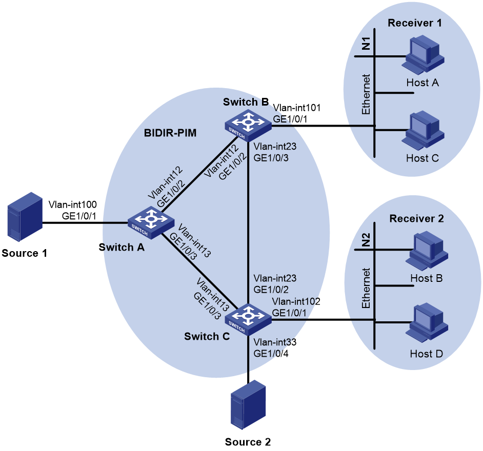
Table 1 Interface and IP address assignment
|
Device |
Interface |
IP address |
Device |
Interface |
IP address |
|
Switch A |
Vlan-int100 |
10.10.1.1/24 |
Switch C |
Vlan-int102 |
10.102.1.1/24 |
|
Switch A |
Vlan-int12 |
10.12.1.1/24 |
Switch C |
Vlan-int13 |
10.13.1.3/24 |
|
Switch A |
Vlan-int13 |
10.13.1.1/24 |
Switch C |
Vlan-int23 |
10.23.1.3/24 |
|
Switch B |
Vlan-int101 |
10.101.1.1/24 |
Switch C |
Vlan-int33 |
|
|
Switch B |
Vlan-int12 |
10.12.1.2/24 |
Source 1 |
— |
10.10.1.2/24 |
|
Switch B |
Vlan-int23 |
10.23.1.2/24 |
Source 2 |
— |
10.33.1.4/24 |
Analysis
To meet the network requirements, perform the following tasks:
· To establish the bidirectional RPT, configure VLAN-interface 12 on Switch A as a C-RP.
· To use the BSR mechanism to dynamically elect the RP, configure VLAN-interface 12 on Switch A as a C-BSR.
· To avoid multicast forwarding interruption when the RP fails, specify the unused IP address 10.13.1.4/24 as the static RP. In this way, the link on the subnet 10.13.1.0/24 becomes the RPL. Switch A and Switch C on the link function as the RPs.
Applicable hardware and software versions
The following matrix shows the hardware and software versions to which this configuration example is applicable:
|
Hardware |
Software version |
|
S6812 switch series S6813 switch series |
Release 66xx |
|
S6550XE-HI switch series |
Release 6008 and later |
|
S6525XE-HI switch series |
Release 6008 and later |
|
S5850 switch series |
Release 8005 and later |
|
S5570S-EI switch series |
Not supported |
|
S5560X-EI switch series |
Release 65xx, Release 66xx |
|
S5560X-HI switch series |
Release 65xx, Release 66xx |
|
S5500V2-EI switch series |
Release 65xx, Release 66xx |
|
ES5500 switch series |
Release 65xx, Release 66xx |
|
MS4520V2-30F switch MS4520V2-30C switch MS4520V2-54C switch |
Release 65xx, Release 66xx |
|
MS4520V2-28S MS4520V2-24TP |
Not supported |
|
S6520X-HI switch series S6520X-EI switch series |
Release 65xx, Release 66xx |
|
S6520X-SI switch series S6520-SI switch series |
Release 65xx, Release 66xx |
|
S5000-EI switch series |
Release 65xx, Release 66xx |
|
MS4600 switch series |
Release 65xx, Release 66xx |
|
ES5500 switch series |
Not supported |
|
S5560S-EI switch series S5560S-SI switch series |
Not supported |
|
S5500V3-24P-SI S5500V3-48P-SI |
Not supported |
|
S5500V3-SI switch series (except S5500V3-24P-SI and S5500V3-48P-SI) |
Not supported |
|
S5170-EI switch series |
Not supported |
|
S5130S-HI switch series S5130S-EI switch series S5130S-SI switch series S5130S-LI switch series |
Not supported |
|
S5120V2-SI switch series S5120V2-LI switch series |
Not supported |
|
S5120V3-EI switch series |
Not supported |
|
S5120V3-36F-SI S5120V3-28P-HPWR-SI S5120V3-54P-PWR-SI |
Not supported |
|
S5120V3-SI switch series (except S5120V3-36F-SI, S5120V3-28P-HPWR-SI, and S5120V3-54P-PWR-SI) |
Not supported |
|
S5120V3-LI switch series |
Not supported |
|
S3600V3-EI switch series |
Not supported |
|
S3600V3-SI switch series |
Not supported |
|
S3100V3-EI switch series S3100V3-SI switch series |
Not supported |
|
S5110V2 switch series |
Not supported |
|
S5110V2-SI switch series |
Not supported |
|
S5000V3-EI switch series S5000V5-EI switch series |
Not supported |
|
S5000E-X switch series S5000X-EI switch series |
Not supported |
|
E128C E152C E500C switch series E500D switch series |
Not supported |
|
MS4320V2 switch series MS4320V3 switch series MS4300V2 switch series MS4320 switch series MS4200 switch series |
Not supported |
|
WS5850-WiNet switch series |
Not supported |
|
WS5820-WiNet switch series WS5810-WiNet switch series |
Not supported |
|
WAS6000 switch series |
Not supported |
|
IE4300-12P-AC IE4300-12P-PWR IE4300-M switch series IE4320 switch series |
Not supported |
Restrictions and guidelines
When you configure BIDIR-PIM, follow these restrictions and guidelines:
· Enable the same PIM mode on the interfaces that belong to the same VPN instance on each switch.
· Configure the same static RP on all the switches in the BIDIR-PIM domain.
· Enable PIM-SM for all interfaces on the switches in the BIDIR-PIM domain.
· Enable IGMP for the interfaces that connect to the stub networks on all the switches in the BIDIR-PIM domain.
Procedures
Configure Switch A
1. Enable IP multicast routing.
<SwitchA> system-view
System View: return to User View with Ctrl+Z.
[SwitchA] multicast routing
[SwitchA-mrib] quit
2. Configure each interface and enable PIM-SM.
# Create VLAN 100, and assign GigabitEthernet 1/0/1 to this VLAN.
[SwitchA] vlan 100
[SwitchA-vlan100] port gigabitethernet 1/0/1
[SwitchA-vlan100] quit
# Assign an IP address to VLAN-interface 100, and enable PIM-SM on the interface.
[SwitchA] interface vlan-interface 100
[SwitchA-Vlan-interface100] ip address 10.10.1.1 24
[SwitchA-Vlan-interface100] pim sm
[SwitchA-Vlan-interface100] quit
# Create VLAN 12, and assign GigabitEthernet 1/0/2 to the VLAN.
[SwitchA] vlan 12
[SwitchA-vlan12] port gigabitethernet 1/0/2
[SwitchA-vlan12] quit
# Assign an IP address to VLAN-interface 12, enable PIM-SM on the interface.
[SwitchA-vlan12] interface vlan-interface 12
[SwitchA-Vlan-interface12] ip address 10.12.1.1 24
[SwitchA-Vlan-interface12] pim sm
[SwitchA-Vlan-interface12] quit
# Create VLAN 13, and assign GigabitEthernet 1/0/3 to the VLAN.
[SwitchA] vlan 13
[SwitchA-vlan13] port gigabitethernet 1/0/3
[SwitchA-vlan13] quit
# Assign an IP address to VLAN-interface 13, enable PIM-SM on the interface.
[SwitchA] interface vlan-interface 13
[SwitchA-Vlan-interface13] ip address 10.13.1.1 24
[SwitchA-Vlan-interface13] pim sm
[SwitchA-Vlan-interface13] quit
3. Configure a C-RP, a C-BSR, and the static RP.
# Configure VLAN-interface 12 as a C-BSR and a C-RP.
[SwitchA] pim
[SwitchA-pim] c-bsr 10.12.1.1
[SwitchA-pim] c-rp 10.12.1.1 bidir
# Specify the unused IP address 10.13.1.4 as a static RP.
[SwitchA-pim] static-rp 10.13.1.4 bidir
4. Enable BIDIR-PIM.
[SwitchA-pim] bidir-pim enable
[SwitchA-pim] quit
5. Configure OSPF.
[SwitchA] ospf 1
[SwitchA-ospf-1] import-route direct
[SwitchA-ospf-1] area 0
[SwitchA-ospf-1-area-0.0.0.0] network 10.0.0.0 0.255.255.255
[SwitchA-ospf-1-area-0.0.0.0] quit
[SwitchA-ospf-1] quit
Configure Switch B
1. Enable IP multicast routing.
<SwitchB> system-view
System View: return to User View with Ctrl+Z.
[SwitchB] multicast routing
[SwitchB-mrib] quit
2. Configure each interface and enable PIM-SM.
# Create VLAN 12, and assign GigabitEthernet 1/0/2 to this VLAN.
[SwitchB] vlan 12
[SwitchB-vlan12] port gigabitethernet 1/0/2
[SwitchB-vlan12] quit
# Assign an IP address to VLAN-interface 12, enable PIM-SM on the interface.
[SwitchB] interface vlan-interface 12
[SwitchB-Vlan-interface12] ip address 10.12.1.2 24
[SwitchB-Vlan-interface12] pim sm
[SwitchB-Vlan-interface12] quit
# Create VLAN 23, and assign GigabitEthernet 1/0/3 to this VLAN.
[SwitchB] vlan 23
[SwitchB-vlan23] port gigabitethernet 1/0/3
[SwitchB-vlan23] quit
# Assign an IP address to VLAN-interface 23, enable PIM-SM on the interface.
[SwitchB] interface vlan-interface 23
[SwitchB-Vlan-interface23] ip address 10.23.1.2 24
[SwitchB-Vlan-interface23] pim sm
[SwitchB-Vlan-interface23] quit
# Create VLAN 101, and assign GigabitEthernet 1/0/1 to this VLAN.
[SwitchB] vlan 101
[SwitchB-vlan101] port gigabitethernet 1/0/1
[SwitchB-vlan101] quit
# Assign an IP address to VLAN-interface 101, enable PIM-SM and IGMP on the interface.
[SwitchB] interface vlan-interface 101
[SwitchB-Vlan-interface101] ip address 10.101.1.1 24
[SwitchB-Vlan-interface101] igmp enable
[SwitchB-Vlan-interface101] quit
3. Specify the unused IP address 10.13.1.4 as a static RP.
[SwitchB] pim
[SwitchB-pim] static-rp 10.13.1.4 bidir
4. Enable BIDIR-PIM.
[SwitchB-pim] bidir-pim enable
[SwitchB-pim] quit
5. Configure OSPF.
[SwitchB] ospf 1
[SwitchB-ospf-1] import-route direct
[SwitchB-ospf-1] area 0
[SwitchB-ospf-1-area-0.0.0.0] network 10.0.0.0 0.255.255.255
[SwitchB-ospf-1-area-0.0.0.0] quit
[SwitchB-ospf-1] quit
Configure Switch C
1. Enable IP multicast routing.
<SwitchC> system-view
System View: return to User View with Ctrl+Z.
[SwitchC] multicast routing
[SwitchC-mrib] quit
2. Configure each interface and enable PIM-SM.
# Create VLAN 33, and assign GigabitEthernet 1/0/4 to this VLAN.
[SwitchC] vlan 33
[SwitchC-vlan33] port gigabitethernet 1/0/4
[SwitchC-vlan33] quit
# Assign an IP address to VLAN-interface 33, enable PIM-SM on the interface.
[SwitchC] interface vlan-interface 33
[SwitchC-Vlan-interface33] ip address 10.33.1.3 24
[SwitchC-Vlan-interface33] pim sm
[SwitchC-Vlan-interface33] quit
# Create VLAN 13, and assign GigabitEthernet 1/0/3 to this VLAN.
[SwitchC] vlan 13
[SwitchC-vlan13] port gigabitethernet 1/0/3
[SwitchC-vlan13] quit
# Assign an IP address to VLAN-interface 13, enable PIM-SM on the interface.
[SwitchC] interface vlan-interface 13
[SwitchC-Vlan-interface13] ip address 10.13.1.3 24
[SwitchC-Vlan-interface13] pim sm
[SwitchC-Vlan-interface13] quit
# Create VLAN 23, and assign GigabitEthernet 1/0/2 to this VLAN.
[SwitchC] vlan 23
[SwitchC-vlan23] port gigabitethernet 1/0/2
[SwitchC-vlan23] quit
# Assign an IP address to VLAN-interface 23, enable PIM-SM on the interface.
[SwitchC] interface vlan-interface 23
[SwitchC-Vlan-interface23] ip address 10.23.1.3 24
[SwitchC-Vlan-interface23] pim sm
[SwitchC-Vlan-interface23] quit
# Create VLAN 102, and assign GigabitEthernet 1/0/1 to this VLAN.
[SwitchC] vlan 102
[SwitchC-vlan102] port gigabitethernet 1/0/1
[SwitchC-vlan102] quit
# Assign an IP address to VLAN-interface 102, enable PIM-SM and IGMP on the interface.
[SwitchC] interface vlan-interface 102
[SwitchC-Vlan-interface102] ip address 10.102.1.1 24
[SwitchC-Vlan-interface102] igmp enable
[SwitchC-Vlan-interface102] quit
3. Specify the unused IP address 10.13.1.4 as a static RP.
[SwitchC] pim
[SwitchC-pim] static-rp 10.13.1.4 bidir
4. Enable BIDIR-PIM
[SwitchC-pim] bidir-pim enable
[SwitchC-pim] quit
5. Configure OSPF.
[SwitchC] ospf 1
[SwitchC-ospf-1] import-route direct
[SwitchC-ospf-1] area 0
[SwitchC-ospf-1-area-0.0.0.0] network 10.0.0.0 0.255.255.255
[SwitchC-ospf-1-area-0.0.0.0] quit
[SwitchC-ospf-1] quit
Verifying the configuration
1. Verify that Switch A, Switch B, and Switch C have established PIM neighbor relationships.
# Display PIM neighbor information on Switch A.
[SwitchA] display pim neighbor
Total Number of Neighbors = 2
Neighbor Interface Uptime Expires DR-Priority Mode
10.12.1.2 Vlan12 00:02:27 00:01:45 1 B
10.13.1.3 Vlan13 00:02:27 00:01:19 1 B
# Display PIM neighbor information on Switch B.
[SwitchB] display pim neighbor
Total Number of Neighbors = 2
Neighbor Interface Uptime Expires DR-Priority Mode
10.12.1.1 Vlan12 00:03:05 00:01:44 1 B
10.23.1.3 Vlan23 00:13:49 00:01:29 1 B
# Display PIM neighbor information on Switch C.
[SwitchC] display pim neighbor
Total Number of Neighbors = 2
Neighbor Interface Uptime Expires DR-Priority Mode
10.13.1.1 Vlan13 00:03:28 00:01:39 1 B
10.23.1.2 Vlan23 00:14:05 00:01:36 1 B
2. Verify that VLAN-interface 12 on Switch A has been elected as the BSR on each switch.
# Display BSR information on Switch A.
[SwitchA] display pim bsr-info
Scope: non-scoped
State: Elected
Bootstrap timer: 00:01:18
Elected BSR address: 10.12.1.1
Priority: 64
Hash mask length: 30
Uptime: 00:04:01
Candidate BSR address: 10.12.1.1
Priority: 64
Hash mask length: 30
# Display BSR information on Switch B.
[SwitchB] display pim bsr-info
Scope: non-scoped
State: Accept Preferred
Bootstrap timer: 00:00:26
Elected BSR address: 10.12.1.1
Priority: 64
Hash mask length: 30
Uptime: 00:10:41
# Display BSR information on Switch C.
[SwitchC] display pim bsr-info
Scope: non-scoped
State: Accept Preferred
Bootstrap timer: 00:02:08
Elected BSR address: 10.12.1.1
Priority: 64
Hash mask length: 30
Uptime: 00:15:41
3. Verify that VLAN-interface 12 on Switch A has been elected as the RP, and verify that the IP address of the static RP is 10.13.1.4 on each switch.
# Display RP information on Switch A.
[SwitchA] display pim rp-info
BSR RP information:
Scope: non-scoped
Group/MaskLen: 224.0.0.0/4 [B]
RP address Priority HoldTime Uptime Expires
10.12.1.1 (local) 192 150 00:06:01 00:02:58
Static RP information:
RP address ACL Mode Preferred
10.13.1.4 ---- bidir No
# Display RP information on Switch B.
[SwatchB] display pim rp-info
BSR RP information:
Scope: non-scoped
Group/MaskLen: 224.0.0.0/4 [B]
RP address Priority HoldTime Uptime Expires
10.12.1.1 192 150 00:06:33 00:02:26
Static RP information:
RP address ACL Mode Preferred
10.13.1.4 ---- bidir No
# Display RP information on Switch C.
[SwitchC] display pim rp-info
BSR RP information:
Scope: non-scoped
Group/MaskLen: 224.0.0.0/4 [B]
RP address Priority HoldTime Uptime Expires
10.12.1.1 192 150 00:06:51 00:02:05
Static RP information:
RP address ACL Mode Preferred
10.13.1.4 ---- bidir No
4. Verify that the DFs have been elected for BIDIR-PIM on each switch.
# Display information about DFs for BIDIR-PIM on Switch A.
[SwitchA] display pim df-info
RP address: 10.12.1.1
Interface: Vlan-interface100
State : Win DF preference: 0
DF metric : 0 DF uptime : 00:01:09
DF address: 10.10.1.1 (local)
Interface: Vlan-interface12
State : - DF preference: -
DF metric : - DF uptime : -
DF address: -
Interface: Vlan-interface13
State : Win DF preference: 0
DF metric : 0 DF uptime : 00:01:10
DF address: 10.13.1.1 (local)
RP address: 10.13.1.4
Interface: Vlan-interface100
State : Win DF preference: 0
DF metric : 0 DF uptime : 00:00:07
DF address: 10.10.1.1 (local)
Interface: Vlan-interface12
State : Win DF preference: 0
DF metric : 0 DF uptime : 00:00:07
DF address: 10.12.1.1 (local)
Interface: Vlan-interface13
State : - DF preference: -
DF metric : - DF uptime : -
DF address: -
# Display information about DFs for BIDIR-PIM on Switch B.
[SwatchB] display pim df-info
RP address: 10.12.1.1
Interface: Vlan-interface12
State : - DF preference: -
DF metric : - DF uptime : -
DF address: -
Interface: Vlan-interface23
State : Win DF preference: 0
DF metric : 0 DF uptime : 00:01:46
DF address: 10.23.1.2 (local)
Interface: Vlan-interface101
State : Win DF preference: 0
DF metric : 0 DF uptime : 00:01:45
DF address: 10.101.1.1 (local)
RP address: 10.13.1.4
Interface: Vlan-interface12
State : Lose DF preference: 0
DF metric : 0 DF uptime : 00:00:44
DF address: 10.12.1.1
Interface: Vlan-interface23
State : Lose DF preference: 0
DF metric : 0 DF uptime : 00:00:53
DF address: 10.23.1.3
Interface: Vlan-interface101
State : Win DF preference: 10
DF metric : 2 DF uptime : 00:00:53
DF address: 10.101.1.1 (local)
# Display information about DFs for BIDIR-PIM on Switch C.
[SwitchC] display pim df-info
RP address: 10.12.1.1
Interface: Vlan-interface102
State : Win DF preference: 10
DF metric : 2 DF uptime : 00:02:07
DF address: 10.102.1.1 (local)
Interface: Vlan-interface33
State : Win DF preference: 10
DF metric : 2 DF uptime : 00:02:06
DF address: 10.33.1.3 (local)
Interface: Vlan-interface13
State : Lose DF preference: 0
DF metric : 0 DF uptime : 00:02:07
DF address: 10.13.1.1
Interface: Vlan-interface23
State : Lose DF preference: 0
DF metric : 0 DF uptime : 00:02:07
DF address: 10.23.1.2
RP address: 10.13.1.4
Interface: Vlan-interface102
State : Win DF preference: 0
DF metric : 0 DF uptime : 00:01:24
DF address: 10.102.1.1 (local)
Interface: Vlan-interface33
State : Win DF preference: 0
DF metric : 0 DF uptime : 00:01:23
DF address: 10.33.1.3 (local)
Interface: Vlan-interface13
State : - DF preference: -
DF metric : - DF uptime : -
DF address: -
Interface: Vlan-interface23
State : Win DF preference: 0
DF metric : 0 DF uptime : 00:01:24
5. Verify that DFs for multicast forwarding are correct on each switch.
# Display information about DFs for multicast forwarding on Switch A.
[SwitchA] display multicast forwarding df-info
Total 2 RPs, 2 matched
00001. RP address: 10.12.1.1
Flags: 0x0
Uptime: 00:02:42
RPF interface: Vlan-interface12
List of 2 DF interfaces:
1: Vlan-interface100
2: Vlan-interface13
00002. RP address: 10.13.1.4
Flags: 0x0
Uptime: 00:01:41
RPF interface: Vlan-interface13
List of 2 DF interfaces:
1: Vlan-interface100
2: Vlan-interface12
# Display information about DFs for multicast forwarding on Switch B.
[SwitchB] display multicast forwarding df-info
Total 2 RPs, 2 matched
00001. RP address: 10.12.1.1
Flags: 0x0
Uptime: 00:03:18
RPF interface: Vlan-interface12
List of 2 DF interfaces:
1: Vlan-interface23
2: Vlan-interface101
00002. RP address: 10.13.1.4
Flags: 0x0
Uptime: 00:02:24
RPF interface: Vlan-interface23
List of 1 DF interfaces:
1: Vlan-interface101
# Display information about DFs for multicast forwarding on Switch C.
[SwitchC] display multicast forwarding df-info
Total 2 RPs, 2 matched
00001. RP address: 10.12.1.1
Flags: 0x0
Uptime: 00:03:38
RPF interface: Vlan-interface23
List of 2 DF interfaces:
1: Vlan-interface102
2: Vlan-interface33
00002. RP address: 10.13.1.4
Flags: 0x0
Uptime: 00:02:41
RPF interface: Vlan-interface13
List of 3 DF interfaces:
1: Vlan-interface33
2: Vlan-interface23
3: Vlan-interface102
6. Send IGMP reports from Host A and Host B to join multicast group 225.1.1.1, and send multicast data from Source 1 and Source 2 to the group. (Details not shown.)
7. Verify that PIM forwarding entries have been correctly established on each switch.
# Display information about PIM routing entries on Switch A.
[SwitchA] display pim routing-table
Total 1 (*, G) entries; 0 (S, G) entries
(*, 225.1.1.1)
RP: 10.12.1.1 (local)
Protocol: pim-bidir, Flag: WC LOC ACT
UpTime: 00:21:59
Upstream interface: Vlan-interface12
Upstream neighbor: NULL
RPF prime neighbor: NULL
Downstream interface(s) information:
Total number of downstreams: 1
1: Vlan-interface12
Protocol: pim-bidir, UpTime: 00:21:59, Expires: -
2: Vlan-interface13
Protocol: pim-bidir, UpTime: 00:03:26, Expires: -
# Display information about PIM routing entries on Switch B.
[SwitchB] display pim routing-table
Total 1 (*, G) entries; 0 (S, G) entries
(*, 225.1.1.1)
RP: 10.12.1.1
Protocol: pim-bidir, Flag: WC LOC ACT
UpTime: 00:23:47
Upstream interface: Vlan-interface12
Upstream neighbor: NULL
RPF prime neighbor: NULL
Downstream interface(s) information:
Total number of downstreams: 3
1: Vlan-interface12
Protocol: pim-bidir, UpTime: 00:23:47, Expires: -
2: Vlan-interface23
Protocol: pim-bidir, UpTime: 00:21:56, Expires: -
3: Vlan-interface101
Protocol: igmp, UpTime: 00:23:47, Expires: -
# Display information about PIM routing entries on Switch C.
[SwitchC] display pim routing-table
Total 1 (*, G) entries; 0 (S, G) entries
(*, 225.1.1.1)
RP: 10.12.1.1
Protocol: pim-bidir, Flag: WC ACT
UpTime: 00:01:45
Upstream interface: Vlan-interface23
Upstream neighbor: 10.23.1.2
RPF prime neighbor: 10.23.1.2
Downstream interface(s) information:
Total number of downstreams: 2
1: Vlan-interface102
Protocol: igmp, UpTime: 00:01:05, Expires: -
2: Vlan-interface23
Protocol: pim-bidir, UpTime: 00:00:53, Expires: -
Configuration files
|
|
IMPORTANT: Support for the port link-mode bridge command depends on the device model. |
· Switch A:
#
ospf 1
area 0.0.0.0
network 10.0.0.0 0.255.255.255
#
vlan 12 to 13
#
vlan 100
#
interface Vlan-interface12
ip address 10.12.1.1 255.255.255.0
pim sm
#
interface Vlan-interface13
ip address 10.13.1.1 255.255.255.0
pim sm
#
interface Vlan-interface100
ip address 10.10.1.1 255.255.255.0
pim sm
#
interface GigabitEthernet1/0/1
port link-mode bridge
port access vlan 100
#
interface GigabitEthernet1/0/2
port link-mode bridge
port access vlan 12
#
interface GigabitEthernet1/0/3
port link-mode bridge
port access vlan 13
#
multicast routing
#
pim
bidir-pim enable
c-bsr 10.12.1.1
c-rp 10.12.1.1 bidir
static-rp 10.13.1.4 bidir
#
· Switch B:
#
ospf 1
area 0.0.0.0
network 10.0.0.0 0.255.255.255
#
vlan 12
#
Vlan 23
#
vlan 101
#
interface Vlan-interface12
ip address 10.12.1.2 255.255.255.0
pim sm
#
interface Vlan-interface23
ip address 10.23.1.2 255.255.255.0
pim sm
#
interface Vlan-interface101
ip address 10.101.1.1 255.255.255.0
igmp enable
#
interface GigabitEthernet1/0/1
port link-mode bridge
port access vlan 101
#
interface GigabitEthernet1/0/2
port link-mode bridge
port access vlan 12
#
interface GigabitEthernet1/0/3
port link-mode bridge
port access vlan 23
#
multicast routing
#
pim
bidir-pim enable
static-rp 10.13.1.4 bidir
#
· Switch C:
#
ospf 1
area 0.0.0.0
network 10.0.0.0 0.255.255.255
#
vlan 13
#
vlan 23
#
vlan 33
#
vlan 102
#
interface Vlan-interface13
ip address 10.13.1.3 255.255.255.0
pim sm
#
interface Vlan-interface23
ip address 10.23.1.3 255.255.255.0
pim sm
#
interface Vlan-interface33
ip address 10.33.1.3 255.255.255.0
pim sm
#
interface Vlan-interface102
ip address 10.102.1.1 255.255.255.0
igmp enable
#
interface GigabitEthernet1/0/1
port link-mode bridge
port access vlan 102
#
interface GigabitEthernet1/0/2
port link-mode bridge
port access vlan 23
#
interface GigabitEthernet1/0/3
port link-mode bridge
port access vlan 13
#
interface GigabitEthernet1/0/4
port link-mode bridge
port access vlan 33
#
multicast routing
#
pim
bidir-pim enable
static-rp 10.13.1.4 bidir
#
