- Table of Contents
-
- H3C Fixed Port Campus Switches Configuration Examples-6W103
- 00-Applicable hardware and software versions
- 01-Login Management Configuration Examples
- 02-RBAC Configuration Examples
- 03-Software Upgrade Examples
- 04-ISSU Configuration Examples
- 05-Software Patching Examples
- 06-Ethernet Link Aggregation Configuration Examples
- 07-Port Isolation Configuration Examples
- 08-Spanning Tree Configuration Examples
- 09-VLAN Configuration Examples
- 10-VLAN Tagging Configuration Examples
- 11-DHCP Snooping Configuration Examples
- 12-Cross-Subnet Dynamic IP Address Allocation Configuration Examples
- 13-IPv6 over IPv4 Tunneling with OSPFv3 Configuration Examples
- 14-IPv6 over IPv4 GRE Tunnel Configuration Examples
- 15-GRE with OSPF Configuration Examples
- 16-OSPF Configuration Examples
- 17-IS-IS Configuration Examples
- 18-BGP Configuration Examples
- 19-Policy-Based Routing Configuration Examples
- 20-OSPFv3 Configuration Examples
- 21-IPv6 IS-IS Configuration Examples
- 22-Routing Policy Configuration Examples
- 23-IGMP Snooping Configuration Examples
- 24-IGMP Configuration Examples
- 25-MLD Snooping Configuration Examples
- 26-IPv6 Multicast VLAN Configuration Examples
- 27-ACL Configuration Examples
- 28-Traffic Policing Configuration Examples
- 29-GTS and Rate Limiting Configuration Examples
- 30-Traffic Filtering Configuration Examples
- 31-AAA Configuration Examples
- 32-Port Security Configuration Examples
- 33-Portal Configuration Examples
- 34-SSH Configuration Examples
- 35-IP Source Guard Configuration Examples
- 36-Ethernet OAM Configuration Examples
- 37-CFD Configuration Examples
- 38-DLDP Configuration Examples
- 39-VRRP Configuration Examples
- 40-BFD Configuration Examples
- 41-NTP Configuration Examples
- 42-SNMP Configuration Examples
- 43-NQA Configuration Examples
- 44-Mirroring Configuration Examples
- 45-sFlow Configuration Examples
- 46-OpenFlow Configuration Examples
- 47-MAC Address Table Configuration Examples
- 48-Static Multicast MAC Address Entry Configuration Examples
- 49-IP Unnumbered Configuration Examples
- 50-MVRP Configuration Examples
- 51-MCE Configuration Examples
- 52-Attack Protection Configuration Examples
- 53-Smart Link Configuration Examples
- 54-RRPP Configuration Examples
- 55-BGP Route Selection Configuration Examples
- 56-IS-IS Route Summarization Configuration Examples
- 57-VXLAN Configuration Examples
- 58-DRNI Configuration Examples
- 59-IRF 3.1 Configuration Examples
- 60-PTP Configuration Examples
- 61-S-MLAG Configuration Examples
- 62-Puppet Configuration Examples
- 63-802.1X Configuration Examples
- 64-MAC Authentication Configuration Examples
- 65-ISATAP Tunnel and 6to4 Tunnel Configuration Examples
- 66-BIDIR-PIM Configuration Examples
- 67-Congestion Avoidance and Queue Scheduling Configuration Examples
- 68-Basic MPLS Configuration Examples
- 69-MPLS L3VPN Configuration Examples
- 70-MPLS OAM Configuration Examples
- 71-EVPN-DCI over an MPLS L3VPN Network Configuration Examples
- 72-DRNI and EVPN Configuration Examples
- 73-Multicast VPN Configuration Examples
- 74-MPLS TE Configuration Examples
- 75-Control Plane-Based QoS Policy Configuration Examples
- 76-Priority Mapping and Queue Scheduling Configuration Examples
- 77-ARP Attack Protection Configuration Examples
- 78-IRF Software Upgrade Configuration Examples
- 79-IRF Member Replacement Configuration Examples
- 80-Layer 3 Multicast on Multicast Source-Side DR System Configuration Examples
- 81-EVPN Multicast Configuration Examples
- Related Documents
-
| Title | Size | Download |
|---|---|---|
| 76-Priority Mapping and Queue Scheduling Configuration Examples | 103.38 KB |
Example: Configuring priority mapping and queue scheduling
Priority configuration for the internal network traffic
Priority configuration for the Internet traffic
Applicable hardware and software versions
Configuring transmission priorities for the internal network traffic
Configuring transmission priorities for the traffic to the Internet
Introduction
This document provides examples for configuring priority mapping and queue scheduling profiles.
Prerequisites
The configuration examples in this document were created and verified in a lab environment, and all the devices were started with the factory default configuration. When you are working on a live network, make sure you understand the potential impact of every command on your network.
This document assumes that you have basic knowledge of priority mapping and queue scheduling profiles.
Example: Configuring priority mapping and queue scheduling
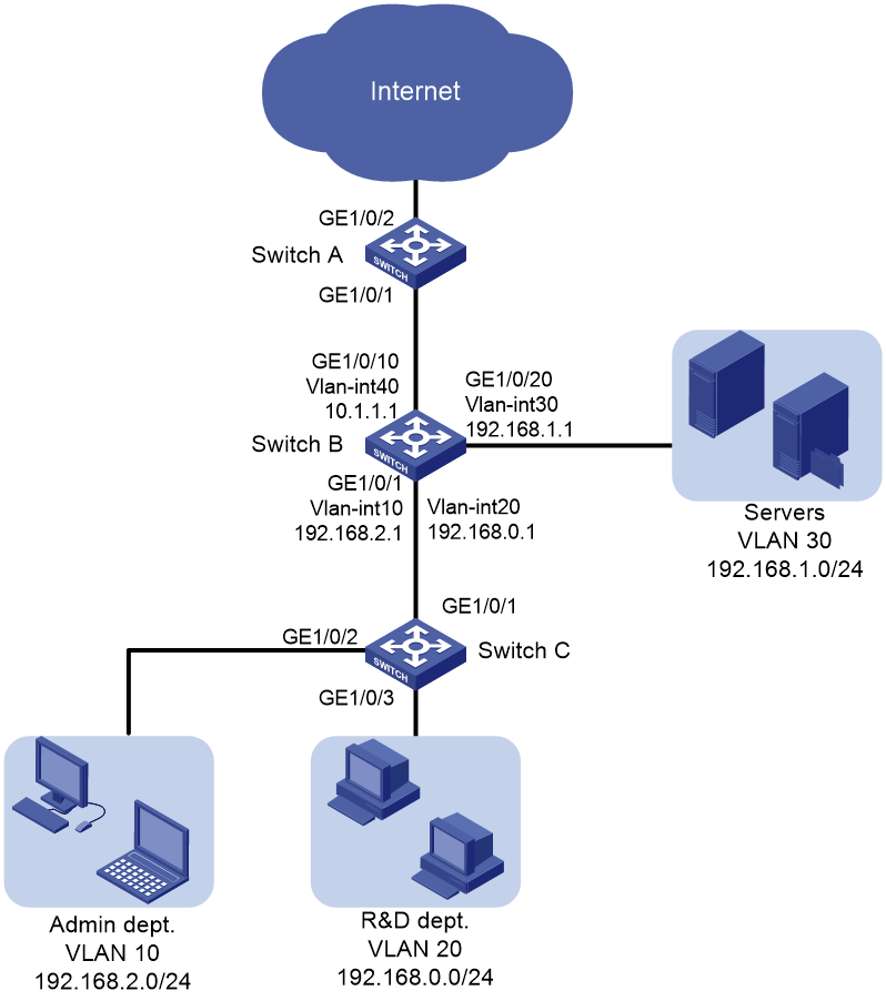
Network configuration
As shown in Figure 1, the Internet-accessing traffic includes the following types: HTTP, FTP, and Email, with the DSCP values 33, 35, and 27, respectively.
Configure priority mapping and queue scheduling to meet the following requirements:
· Access to the internal server farm—The traffic from the Administration department takes priority over the traffic from the R&D department. When congestion occurs, they are scheduled at a ratio of 2:1.
· Access to the Internet—The traffic from the Administration department takes priority over the traffic from the R&D department. When congestion occurs, the traffic from the Administration department is scheduled preferentially. The traffic from the R&D department is scheduled when no traffic from the Administration department exists. The three types of Internet-accessing traffic are transmitted in the following priority order: HTTP > FTP > Email. When congestion occurs, the three types of traffic are transmitted at a ratio of 2:1:1.
Analysis
Priority configuration for the internal network traffic
To meet the network requirements, you must perform the following tasks:
· For packets from the two departments to be marked with different 802.1p priorities, configure different port priority values for the interfaces connected to the two departments.
· Because the 802.1p priorities are carried in VLAN tags, you must configure GigabitEthernet 1/0/1 on Switch C to send packets carrying VLAN tags. This example uses the port link type trunk.
· To make the marked 802.1p priority actually affect the packet transmission, configure trusting the 802.1p priorities of received packets on all input interfaces along the transmission path.
· To schedule packets from different queues at the specified ratio when congestion occurs, enable WRR queuing and configure different weights for queues.
Priority configuration for the Internet traffic
To meet the network requirements, you must perform the following tasks:
· To completely prioritize the traffic from the Administration department when the interface is congested in the outbound direction, perform the following tasks:
¡ Configure SP queuing on the interface.
¡ Assign the traffic from the Administration department to a higher-priority queue.
· To determine the transmission priority based on the upper-layer protocols, configure trusting the DSCP values on the interface, so that the interface can enqueue packets based on the DSCP values.
· To assign packets with DSCP value 33 to a higher-priority queue, modify the DSCP-to-802.1p priority mapping table to map DSCP value 33 to a higher 802.1p priority value than the default. By default, DSCP values 33, 35, 27 are mapped to local precedence values 4, 4, and 3, respectively, based on the DSCP-to-802.1p priority mapping table and the 802.1p-to-local priority mapping table.
· To schedule packets from different queues at the specified ratio when congestion occurs, enable WRR queuing and configure different weights for queues.
Applicable hardware and software versions
The following matrix shows the hardware and software versions to which this configuration example is applicable:
|
Hardware |
Software version |
|
S6812 switch series S6813 switch series |
Release 66xx |
|
S6550XE-HI switch series |
Release 6008 and later |
|
S6525XE-HI switch series |
Release 6008 and later |
|
S5850 switch series |
Release 8005 and later |
|
S5570S-EI switch series |
Release 11xx |
|
S5560X-EI switch series |
Not supported |
|
S5560X-HI switch series |
Not supported |
|
S5500V2-EI switch series |
Not supported |
|
MS4520V2-30F switch |
Not supported |
|
MS4520V2-54C switch |
Not supported |
|
MS4520V2-24TP switch |
Not supported |
|
S6520X-EI switch series |
Not supported |
|
S6520-SI switch series |
Not supported |
|
S5000-EI switch series |
Not supported |
|
MS4600 switch series |
Not supported |
|
ES5500 switch series |
Not supported |
|
S5560S-SI switch series |
Not supported |
|
S5500V3-24P-SI S5500V3-48P-SI |
Not supported |
|
S5500V3-SI switch series (except S5500V3-24P-SI and S5500V3-48P-SI) |
Release 11xx |
|
S5170-EI switch series |
Release 11xx |
|
S5130S-LI switch series |
Not supported |
|
S5120V2-LI switch series |
Not supported |
|
S5120V3-EI switch series |
Release 11xx |
|
S5120V3-36F-SI S5120V3-28P-HPWR-SI S5120V3-54P-PWR-SI |
Release 11xx |
|
S5120V3-SI switch series (except S5120V3-36F-SI, S5120V3-28P-HPWR-SI, and S5120V3-54P-PWR-SI) |
Not supported |
|
S5120V3-LI switch series |
Not supported |
|
S3600V3-EI switch series |
Release 11xx |
|
S3600V3-SI switch series |
Release 11xx |
|
S3100V3-SI switch series |
Not supported |
|
S5110V2 switch series |
Not supported |
|
S5110V2-SI switch series |
Not supported |
|
S5000V5-EI switch series |
Not supported |
|
S5000E-X switch series S5000X-EI switch series |
Not supported |
|
E500D switch series |
Not supported |
|
MS4320V3 switch series MS4200 switch series |
Not supported |
|
WS5850-WiNet switch series |
Not supported |
|
WS5810-WiNet switch series |
Not supported |
|
WAS6000 switch series |
Not supported |
|
IE4300-12P-AC switch IE4320 switch series |
Not supported |
Procedures
Configuring transmission priorities for the internal network traffic
1. Configure Switch C:
# Create VLANs 10 and 20.
<SwitchC> system-view
[SwitchC] vlan 10
[SwitchC-vlan10] quit
[SwitchC] vlan 20
[SwitchC-vlan20] quit
# Assign interface GigabitEthernet 1/0/2 to VLAN 10, and set the port priority to 6 for the interface. This enables the traffic from the Administration department to be marked with 802.1p priority value 6.
[SwitchC] interface gigabitethernet 1/0/2
[SwitchC-GigabitEthernet1/0/2] port access vlan 10
[SwitchC-GigabitEthernet1/0/2] qos priority 6
[SwitchC-GigabitEthernet1/0/2] quit
# Assign interface GigabitEthernet 1/0/3 to VLAN 20, and set the port priority to 4 for the interface. This enables the traffic from the R&D department to be marked with 802.1p priority value 4.
[SwitchC] interface gigabitethernet 1/0/3
[SwitchC-GigabitEthernet1/0/3] port access vlan 20
[SwitchC-GigabitEthernet1/0/3] qos priority 4
[SwitchC-GigabitEthernet1/0/3] quit
# Configure interface GigabitEthernet 1/0/1 as a trunk port, assign the interface to VLAN 10 and VLAN 20, and remove the interface from VLAN 1.
[SwitchC] interface gigabitethernet 1/0/1
[SwitchC-GigabitEthernet1/0/1] port link-type trunk
[SwitchC-GigabitEthernet1/0/1] port trunk permit vlan 10 20
[SwitchC-GigabitEthernet1/0/1] undo port trunk permit vlan 1
[SwitchC-GigabitEthernet1/0/1] quit
2. Configure Switch B:
# Create VLANs 10, 20, 30, and 40.
<SwitchB> system-view
[SwitchB] vlan 10
[SwitchB-vlan10] quit
[SwitchB] vlan 20
[SwitchB-vlan20] quit
[SwitchB] vlan 30
[SwitchB-vlan30] quit
[SwitchB] vlan 40
[SwitchB-vlan40] quit
# Configure interface GigabitEthernet 1/0/1 as a trunk port.
[SwitchB] interface gigabitethernet 1/0/1
[SwitchB-GigabitEthernet1/0/1] port link-type trunk
# Assign interface GigabitEthernet 1/0/1 to VLANs 10 and 20.
[SwitchB-GigabitEthernet1/0/1] port trunk permit vlan 10 20
# Remove interface GigabitEthernet 1/0/1 from VLAN 1.
[SwitchB-GigabitEthernet1/0/1] undo port trunk permit vlan 1
# Configure GigabitEthernet 1/0/1 to trust the 802.1p priority of received packets. Based on the 802.1p-to-local priority mapping table, traffic with 802.1p priority 4 is assigned to queue 4, and traffic with 802.1p priority 6 is assigned to queue 6.
[SwitchB-GigabitEthernet1/0/1] qos trust dot1p
[SwitchB-GigabitEthernet1/0/1] quit
# Assign interface GigabitEthernet 1/0/20 to VLAN 30.
[SwitchB] interface gigabitethernet 1/0/20
[SwitchB-GigabitEthernet1/0/20] port access vlan 30
# Create VLAN interfaces and configure routing protocols to enable communication between network segments. For more information about these configurations, see Layer 3—IP Routing Configuration Guide in the configuration guides for you switch.
# Enable byte-count WRR on interface GigabitEthernet 1/0/20. By default, byte-count WRR is enabled.
[SwitchB-GigabitEthernet1/0/20] qos wrr byte-count
# Configure the weight of queue 6 as two times that of queue 4. In this example, set the weight value to 4 for queue 6 and 2 for queue 4.
[SwitchB-GigabitEthernet1/0/20] qos wrr 4 group 1 byte-count 2
[SwitchB-GigabitEthernet1/0/20] qos wrr 6 group 1 byte-count 4
[SwitchB-GigabitEthernet1/0/20] quit
# Assign interface GigabitEthernet 1/0/10 to VLAN 40.
[SwitchB] interface gigabitethernet 1/0/10
[SwitchB-GigabitEthernet1/0/10] port access vlan 40
[SwitchB-GigabitEthernet1/0/10] quit
Configuring transmission priorities for the traffic to the Internet
1. Configure Switch B:
# Enable SP queuing on interface GigabitEthernet 1/0/10.
[SwitchB] interface gigabitethernet 1/0/10
[SwitchB-GigabitEthernet1/0/10] qos sp
2. Configure Switch A:
# Configure interface GigabitEthernet 1/0/1 to trust the DSCP values of received packets.
[SwitchA] interface gigabitethernet 1/0/1
[SwitchA-GigabitEthernet1/0/1] qos trust dscp
# Modify the DSCP-to-802.1p priority mapping table to map DSCP value 33 to 802.1p priority 5 (queue 5).
[SwitchA] qos map-table dscp-dot1p
[SwitchA-maptbl-dscp-dot1p] import 33 export 5
[SwitchA-maptbl-dscp-dot1p] quit
The configuration assigns the three types of packets (HTTP, FTP, and Email) to queues 5, 4, and 3, respectively.
# Enable byte-count WRR on interface GigabitEthernet 1/0/2. By default, byte-count WRR is enabled.
[SwitchA] interface gigabitethernet 1/0/2
[SwitchA-GigabitEthernet1/0/2] qos wrr byte-count
# Set the weights of the three queues at a ratio of 2:1:1 (6, 3, and 3 in this example).
[SwitchA-GigabitEthernet1/0/2] qos wrr 5 group 1 byte-count 6
[SwitchA-GigabitEthernet1/0/2] qos wrr 4 group 1 byte-count 3
[SwitchA-GigabitEthernet1/0/2] qos wrr 3 group 1 byte-count 3
Verifying the configuration
Verify the configuration on any interface on any switch, for example, GigabitEthernet 1/0/2 on Switch A.
# Verify the WRR configuration.
[SwitchA] display qos queue wrr interface gigabitethernet 1/0/2
Interface: GigabitEthernet1/0/2
Queue ID Queue name Group Byte count
---------------------------------------------------
0 be 1 1
1 af1 1 2
2 af2 1 3
3 af3 1 3
4 af4 1 3
5 ef 1 6
6 cs6 1 13
7 cs7 1 15
Configuration files
|
|
IMPORTANT: The port link-mode bridge command might be displayed in the configuration files of some switches. |
· Switch A:
#
qos map-table dscp-dot1p
import 33 export 5
#
interface GigabitEthernet1/0/1
port link-mode bridge
qos trust dscp
#
interface GigabitEthernet1/0/2
port link-mode bridge
qos wrr af3 group 1 byte-count 3
qos wrr af4 group 1 byte-count 3
qos wrr ef group 1 byte-count 6
#
return
· Switch B:
#
vlan 10
#
vlan 20
#
vlan 30
#
vlan 40
#
interface GigabitEthernet1/0/1
port link-mode bridge
port link-type trunk
undo port trunk permit vlan 1
port trunk permit vlan 10 20
qos trust dot1p
#
interface GigabitEthernet1/0/10
port link-mode bridge
port access vlan 40
#
interface GigabitEthernet1/0/20
port link-mode bridge
port access vlan 30
qos wrr af4 group 1 byte-count 2
qos wrr cs6 group 1 byte-count 4
#
return
· Switch C:
#
vlan 10
#
vlan 20
#
interface GigabitEthernet1/0/1
port link-mode bridge
port link-type trunk
undo port trunk permit vlan 1
port trunk permit vlan 10 20
#
interface GigabitEthernet1/0/2
port link-mode bridge
port access vlan 10
qos priority 6
#
interface GigabitEthernet1/0/3
port link-mode bridge
port access vlan 20
qos priority 4
#
return
