- Table of Contents
-
- H3C Fixed Port Campus Switches Configuration Examples-6W103
- 00-Applicable hardware and software versions
- 01-Login Management Configuration Examples
- 02-RBAC Configuration Examples
- 03-Software Upgrade Examples
- 04-ISSU Configuration Examples
- 05-Software Patching Examples
- 06-Ethernet Link Aggregation Configuration Examples
- 07-Port Isolation Configuration Examples
- 08-Spanning Tree Configuration Examples
- 09-VLAN Configuration Examples
- 10-VLAN Tagging Configuration Examples
- 11-DHCP Snooping Configuration Examples
- 12-Cross-Subnet Dynamic IP Address Allocation Configuration Examples
- 13-IPv6 over IPv4 Tunneling with OSPFv3 Configuration Examples
- 14-IPv6 over IPv4 GRE Tunnel Configuration Examples
- 15-GRE with OSPF Configuration Examples
- 16-OSPF Configuration Examples
- 17-IS-IS Configuration Examples
- 18-BGP Configuration Examples
- 19-Policy-Based Routing Configuration Examples
- 20-OSPFv3 Configuration Examples
- 21-IPv6 IS-IS Configuration Examples
- 22-Routing Policy Configuration Examples
- 23-IGMP Snooping Configuration Examples
- 24-IGMP Configuration Examples
- 25-MLD Snooping Configuration Examples
- 26-IPv6 Multicast VLAN Configuration Examples
- 27-ACL Configuration Examples
- 28-Traffic Policing Configuration Examples
- 29-GTS and Rate Limiting Configuration Examples
- 30-Traffic Filtering Configuration Examples
- 31-AAA Configuration Examples
- 32-Port Security Configuration Examples
- 33-Portal Configuration Examples
- 34-SSH Configuration Examples
- 35-IP Source Guard Configuration Examples
- 36-Ethernet OAM Configuration Examples
- 37-CFD Configuration Examples
- 38-DLDP Configuration Examples
- 39-VRRP Configuration Examples
- 40-BFD Configuration Examples
- 41-NTP Configuration Examples
- 42-SNMP Configuration Examples
- 43-NQA Configuration Examples
- 44-Mirroring Configuration Examples
- 45-sFlow Configuration Examples
- 46-OpenFlow Configuration Examples
- 47-MAC Address Table Configuration Examples
- 48-Static Multicast MAC Address Entry Configuration Examples
- 49-IP Unnumbered Configuration Examples
- 50-MVRP Configuration Examples
- 51-MCE Configuration Examples
- 52-Attack Protection Configuration Examples
- 53-Smart Link Configuration Examples
- 54-RRPP Configuration Examples
- 55-BGP Route Selection Configuration Examples
- 56-IS-IS Route Summarization Configuration Examples
- 57-VXLAN Configuration Examples
- 58-DRNI Configuration Examples
- 59-IRF 3.1 Configuration Examples
- 60-PTP Configuration Examples
- 61-S-MLAG Configuration Examples
- 62-Puppet Configuration Examples
- 63-802.1X Configuration Examples
- 64-MAC Authentication Configuration Examples
- 65-ISATAP Tunnel and 6to4 Tunnel Configuration Examples
- 66-BIDIR-PIM Configuration Examples
- 67-Congestion Avoidance and Queue Scheduling Configuration Examples
- 68-Basic MPLS Configuration Examples
- 69-MPLS L3VPN Configuration Examples
- 70-MPLS OAM Configuration Examples
- 71-EVPN-DCI over an MPLS L3VPN Network Configuration Examples
- 72-DRNI and EVPN Configuration Examples
- 73-Multicast VPN Configuration Examples
- 74-MPLS TE Configuration Examples
- 75-Control Plane-Based QoS Policy Configuration Examples
- 76-Priority Mapping and Queue Scheduling Configuration Examples
- 77-ARP Attack Protection Configuration Examples
- 78-IRF Software Upgrade Configuration Examples
- 79-IRF Member Replacement Configuration Examples
- 80-Layer 3 Multicast on Multicast Source-Side DR System Configuration Examples
- 81-EVPN Multicast Configuration Examples
- Related Documents
-
| Title | Size | Download |
|---|---|---|
| 56-IS-IS Route Summarization Configuration Examples | 81.78 KB |
Example: Configuring IS-IS route summarization
Applicable hardware and software versions
Configuring IP addresses for interfaces
Configuring IS-IS route summarization
Introduction
This document provides IS-IS route summarization configuration examples.
Prerequisites
The configuration examples in this document were created and verified in a lab environment, and all the devices were started with the factory default configuration. When you are working on a live network, make sure you understand the potential impact of every command on your network.
This document assumes that you have basic knowledge of IS-IS route summarization.
Example: Configuring IS-IS route summarization
Network configuration
As shown in Figure 1, the five departments of a company use IS-IS to connect to the backbone network. The five departments are assigned the networks 192.168.1.0/24, 192.168.2.0/24, 192.168.3.0/24, 192.168.4.0/24, and 192.168.5.0/24. Configure IS-IS route summarization to reduce routing entries and save system resources for Device B.
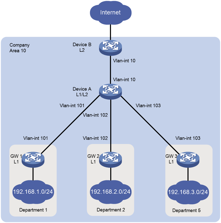
Table 1 Interface and IP address assignment
|
Device |
Interface |
IP address |
Device |
Interface |
IP address |
|
Device A |
Vlan-int10 |
172.16.1.1/24 |
Device B |
Vlan-int10 |
172.168.1.2/24 |
|
Vlan-int101 |
10.1.1.1/24 |
GW 1 |
Vlan-int101 |
10.1.1.2/24 |
|
|
Vlan-int102 |
10.1.2.1/24 |
GW 2 |
Vlan-int102 |
10.1.2.2/24 |
|
|
Vlan-int103 |
10.1.3.1/24 |
GW3 |
Vlan-int103 |
10.1.3.2/24 |
Analysis
Configure route summarization on Device A because route summarization applies only to locally generated LSPs.
To avoid blackhole routes, set the summary route to 192.168.0.0/22.
Applicable hardware and software versions
The following matrix shows the hardware and software versions to which this configuration example is applicable:
|
Hardware |
Software version |
|
S6812 switch series S6813 switch series |
|
|
S6550XE-HI switch series |
Release 6008 and later |
|
S6525XE-HI switch series |
Release 6008 and later |
|
S5850 switch series |
Release 8005 and later |
|
S5570S-EI switch series |
Release 11xx |
|
S5560X-EI switch series |
Release 63xx, Release 65xx, Release 66xx |
|
S5560X-HI switch series |
Release 63xx, Release 65xx, Release 66xx |
|
S5500V2-EI switch series |
Release 63xx, Release 65xx, Release 66xx |
|
MS4520V2-30F switch |
Release 63xx, Release 65xx, Release 66xx |
|
MS4520V2-30C switch MS4520V2-54C switch |
Release 65xx, Release 66xx |
|
MS4520V2-28S switch MS4520V2-24TP switch |
Release 63xx |
|
S6520X-HI switch series S6520X-EI switch series |
Release 63xx, Release 65xx, Release 66xx |
|
S6520X-SI switch series S6520-SI switch series |
Release 63xx, Release 65xx, Release 66xx |
|
S5000-EI switch series |
Release 63xx, Release 65xx, Release 66xx |
|
MS4600 switch series |
Release 63xx, Release 65xx, Release 66xx |
|
ES5500 switch series |
Release 63xx, Release 65xx, Release 66xx |
|
S5560S-EI switch series S5560S-SI switch series |
Release 63xx |
|
S5500V3-24P-SI S5500V3-48P-SI |
Release 63xx |
|
S5500V3-SI switch series (except S5500V3-24P-SI and S5500V3-48P-SI) |
Release 11xx |
|
S5170-EI switch series |
Not supported |
|
S5130S-HI switch series S5130S-EI switch series S5130S-SI switch series S5130S-LI switch series |
Not supported |
|
S5120V2-SI switch series S5120V2-LI switch series |
Not supported |
|
S5120V3-EI switch series |
Not supported |
|
S5120V3-36F-SI S5120V3-28P-HPWR-SI S5120V3-54P-PWR-SI |
Not supported |
|
S5120V3-SI switch series (except S5120V3-36F-SI, S5120V3-28P-HPWR-SI, and S5120V3-54P-PWR-SI) |
Not supported |
|
S5120V3-LI switch series |
Not supported |
|
S3600V3-EI switch series |
Release 11xx |
|
S3600V3-SI switch series |
Not supported |
|
S3100V3-EI switch series S3100V3-SI switch series |
Not supported |
|
S5110V2 switch series |
Not supported |
|
S5110V2-SI switch series |
Not supported |
|
S5000V3-EI switch series S5000V5-EI switch series |
Not supported |
|
S5000E-X switch series S5000X-EI switch series |
Not supported |
|
E128C switch E152C switch E500C switch series E500D switch series |
Not supported |
|
MS4320V2 switch series MS4320V3 switch series MS4300V2 switch series MS4320 switch series MS4200 switch series |
Not supported |
|
WS5850-WiNet switch series |
Release 63xx |
|
WS5820-WiNet switch series WS5810-WiNet switch series |
Not supported |
|
WAS6000 switch series |
Not supported |
|
IE4300-12P-AC switch IE4300-12P-PWR switch IE4300-M switch series IE4320 switch series |
Not supported |
Procedures
Configuring IP addresses for interfaces
# Configure an IP address for the interface VLAN-interface 10 on Device A.
<DeviceA> system-view
[DeviceA] interface vlan-interface 10
[DeviceA-Vlan-interface10] ip address 172.16.1.1 24
[DeviceA-Vlan-interface10] quit
# Configure IP addresses for other interfaces as shown in Figure 1 in the same way VLAN-interface 10 is configured. (Details not shown.)
Configuring basic IS-IS
Configuring Device A
# Enable IS-IS on Device A and configure Device A as a Level-1-2 router.
[DeviceA] isis 1
[DeviceA-isis-1] network-entity 10.0000.0000.0001.00
[DeviceA-isis-1] is-level level-1-2
[DeviceA-isis-1] quit
# Enable IS-IS on the interface VLAN-interface 10.
[DeviceA] interface vlan-interface 10
[DeviceA–Vlan-interface10] isis enable 1
[DeviceA–Vlan-interface10] quit
# Configure other interfaces in the same way VLAN-interface 10 is configured. (Details not shown.)
Configuring Device B
# Enable IS-IS on Device B and configure Device B as a Level-2 router.
[DeviceB] isis 1
[DeviceB-isis-1] network-entity 10.0000.0000.0002.00
[DeviceB-isis-1] is-level level-2
[DeviceB-isis-1] quit
# Enable IS-IS on the interface VLAN-interface 10.
[DeviceB] interface vlan-interface 10
[DeviceB–Vlan-interface10] isis enable 1
[DeviceB–Vlan-interface10] quit
Configuring the gateways
# Enable IS-IS on GW 1 and configure GW 1 as a Level-1 router.
[GW1] isis 1
[GW1-isis-1] network-entity 10.0001.0001.0001.00
[GW1-isis-1] is-level level-1
[GW1-isis-1] quit
# Enable IS-IS on the interface VLAN-interface 11.
[GW1] interface vlan-interface 11
[GW1–Vlan-interface11] isis enable 1
[GW1–Vlan-interface11] quit
# Configure other gateways in the same way GW 1 is configured. (Details not shown.)
Displaying IS-IS routing information on Device B
# Display IS-IS routing information on Device B to view the network address of each department.
[DeviceB] display isis route
Route information for IS-IS(1)
------------------------------
Level-2 IPv4 Forwarding Table
-----------------------------
IPv4 Destination IntCost ExtCost ExitInterface NextHop Flags
-------------------------------------------------------------------------------
192.168.1.0/24 30 NULL Vlan10 172.16.1.1 R/-/-
10.1.1.0/24 20 NULL Vlan10 172.16.1.1 R/-/-
192.168.2.0/24 30 NULL Vlan10 172.16.1.1 R/-/-
10.1.2.0/24 20 NULL Vlan10 172.16.1.1 R/-/-
192.168.3.0/24 30 NULL Vlan10 172.16.1.1 R/-/-
10.1.3.0/24 20 NULL Vlan10 172.16.1.1 R/-/-
172.16.1.0/24 10 NULL Vlan10 Direct D/L/-
Flags: D-Direct, R-Added to Rib, L-Advertised in LSPs, U-Up/Down Bit Set
Configuring IS-IS route summarization
# Configure IS-IS route summarization on Device A.
[DeviceA] isis 1
[DeviceA] address-family ipv4
[DeviceA-isis-1-ipv4]summary 192.168.0.0 22
Verifying the configuration
# Display IS-IS routing information on Device B.
[DeviceB] display isis route
Route information for IS-IS(1)
------------------------------
Level-2 IPv4 Forwarding Table
-----------------------------
IPv4 Destination IntCost ExtCost ExitInterface NextHop Flags
-------------------------------------------------------------------------------
10.1.1.0/24 20 NULL Vlan10 172.16.1.1 R/-/-
10.1.2.0/24 20 NULL Vlan10 172.16.1.1 R/-/-
10.1.3.0/24 20 NULL Vlan10 172.16.1.1 R/-/-
172.16.1.0/24 10 NULL Vlan10 Direct D/L/-
192.168.0.0/22 30 NULL Vlan10 172.16.1.1 R/-/-
Flags: D-Direct, R-Added to Rib, L-Advertised in LSPs, U-Up/Down Bit Set
The output shows that the networks have been summarized into a single network 192.168.0.0/22.
Configuration files
· Device A:
#
isis 1
network-entity 10.0000.0000.0001.00
#
address-family ipv4 unicast
summary 192.168.0.0 255.255.252.0
#
vlan 10
#
vlan 101 to 103
#
interface vlan-interface10
ip address 172.16.1.1 255.255.255.0
isis enable 1
#
interface vlan-interface101
ip address 10.1.1.1 255.255.255.0
isis enable 1
#
interface vlan-interface102
ip address 10.1.2.1 255.255.255.0
isis enable 1
#
interface vlan-interface103
ip address 10.1.3.1 255.255.255.0
isis enable 1
#
· Device B:
#
isis 1
is-level level-2
network-entity 10.0000.0000.0002.00
#
vlan 10
#
interface vlan-interface10
ip address 172.16.1.2 255.255.255.0
isis enable 1
#
· GW 1:
#
isis 1
is-level level-1
network-entity 10.0001.0001.0001.00
#
vlan 11
#
vlan 101
#
interface vlan-interface101
ip address 10.1.1.2 255.255.255.0
isis enable 1
#
interface vlan-interface11
ip address 192.168.1.1 255.255.255.0
isis enable 1
#
· The configuration files for other gateways are similar to the configuration file for GW 1. (Details not shown.)
