- Table of Contents
-
- H3C Fixed Port Campus Switches Configuration Examples-6W103
- 00-Applicable hardware and software versions
- 01-Login Management Configuration Examples
- 02-RBAC Configuration Examples
- 03-Software Upgrade Examples
- 04-ISSU Configuration Examples
- 05-Software Patching Examples
- 06-Ethernet Link Aggregation Configuration Examples
- 07-Port Isolation Configuration Examples
- 08-Spanning Tree Configuration Examples
- 09-VLAN Configuration Examples
- 10-VLAN Tagging Configuration Examples
- 11-DHCP Snooping Configuration Examples
- 12-Cross-Subnet Dynamic IP Address Allocation Configuration Examples
- 13-IPv6 over IPv4 Tunneling with OSPFv3 Configuration Examples
- 14-IPv6 over IPv4 GRE Tunnel Configuration Examples
- 15-GRE with OSPF Configuration Examples
- 16-OSPF Configuration Examples
- 17-IS-IS Configuration Examples
- 18-BGP Configuration Examples
- 19-Policy-Based Routing Configuration Examples
- 20-OSPFv3 Configuration Examples
- 21-IPv6 IS-IS Configuration Examples
- 22-Routing Policy Configuration Examples
- 23-IGMP Snooping Configuration Examples
- 24-IGMP Configuration Examples
- 25-MLD Snooping Configuration Examples
- 26-IPv6 Multicast VLAN Configuration Examples
- 27-ACL Configuration Examples
- 28-Traffic Policing Configuration Examples
- 29-GTS and Rate Limiting Configuration Examples
- 30-Traffic Filtering Configuration Examples
- 31-AAA Configuration Examples
- 32-Port Security Configuration Examples
- 33-Portal Configuration Examples
- 34-SSH Configuration Examples
- 35-IP Source Guard Configuration Examples
- 36-Ethernet OAM Configuration Examples
- 37-CFD Configuration Examples
- 38-DLDP Configuration Examples
- 39-VRRP Configuration Examples
- 40-BFD Configuration Examples
- 41-NTP Configuration Examples
- 42-SNMP Configuration Examples
- 43-NQA Configuration Examples
- 44-Mirroring Configuration Examples
- 45-sFlow Configuration Examples
- 46-OpenFlow Configuration Examples
- 47-MAC Address Table Configuration Examples
- 48-Static Multicast MAC Address Entry Configuration Examples
- 49-IP Unnumbered Configuration Examples
- 50-MVRP Configuration Examples
- 51-MCE Configuration Examples
- 52-Attack Protection Configuration Examples
- 53-Smart Link Configuration Examples
- 54-RRPP Configuration Examples
- 55-BGP Route Selection Configuration Examples
- 56-IS-IS Route Summarization Configuration Examples
- 57-VXLAN Configuration Examples
- 58-DRNI Configuration Examples
- 59-IRF 3.1 Configuration Examples
- 60-PTP Configuration Examples
- 61-S-MLAG Configuration Examples
- 62-Puppet Configuration Examples
- 63-802.1X Configuration Examples
- 64-MAC Authentication Configuration Examples
- 65-ISATAP Tunnel and 6to4 Tunnel Configuration Examples
- 66-BIDIR-PIM Configuration Examples
- 67-Congestion Avoidance and Queue Scheduling Configuration Examples
- 68-Basic MPLS Configuration Examples
- 69-MPLS L3VPN Configuration Examples
- 70-MPLS OAM Configuration Examples
- 71-EVPN-DCI over an MPLS L3VPN Network Configuration Examples
- 72-DRNI and EVPN Configuration Examples
- 73-Multicast VPN Configuration Examples
- 74-MPLS TE Configuration Examples
- 75-Control Plane-Based QoS Policy Configuration Examples
- 76-Priority Mapping and Queue Scheduling Configuration Examples
- 77-ARP Attack Protection Configuration Examples
- 78-IRF Software Upgrade Configuration Examples
- 79-IRF Member Replacement Configuration Examples
- 80-Layer 3 Multicast on Multicast Source-Side DR System Configuration Examples
- 81-EVPN Multicast Configuration Examples
- Related Documents
-
| Title | Size | Download |
|---|---|---|
| 22-Routing Policy Configuration Examples | 106.70 KB |
Introduction
This document provides routing policy configuration examples.
Routing policies control routing paths by filtering and modifying routing information. Routing policies can filter advertised, received, and redistributed routes, and modify attributes for specific routes.
Prerequisites
This document is not restricted to specific software or hardware versions.
The configuration examples in this document were created and verified in a lab environment, and all the devices were started with the factory default configuration. When you are working on a live network, make sure you understand the potential impact of every command on your network.
This document assumes that you have basic knowledge of routing polices.
Example: Configuring routing polices
Network configuration
As shown in Figure 1, a company's two departments reside in different ASs. Device A and Device F are the egress devices of the two departments. OSPF is the IGP protocol in AS 100.
· Configure BGP to make the two departments reachable to each other.
· Configure routing polices to specify the link Device B<—>Device C<—>Device D as the primary link to forward traffic between Device A and Device F. When the primary link fails, the link Device B<—>Device E<—>Device D forwards the traffic.
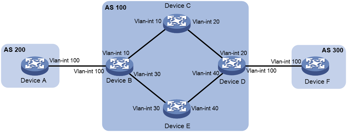
Table 1 Interface and IP address assignment
|
Device |
Interface |
IP address |
Device |
Interface |
IP address |
|
Device A |
Vlan-int100 |
120.1.0.1/24 |
Device D |
Vlan-int20 |
10.2.0.101/24 |
|
Device B |
Vlan-int10 |
10.1.0.101/24 |
|
Vlan-int40 |
13.1.1.101/24 |
|
|
Vlan-int30 |
192.168.0.101/24 |
|
Vlan-int100 |
120.2.0.2/24 |
|
|
Vlan-int100 |
120.1.0.2/24 |
Device E |
Vlan-int30 |
192.168.0.102/24 |
|
Device C |
Vlan-int10 |
10.1.0.102/24 |
|
Vlan-int40 |
13.1.1.102/24 |
|
|
Vlan-int20 |
10.2.0.102/24 |
Device F |
Vlan-int100 |
120.2.0.1/24 |
Analysis
To meet the network requirements, you must perform the following tasks:
· Configure the link Device B<—>Device C<—>Device D as the primary link:
¡ On Device B, set the local preference to 200 for the path Device D—>Device C—>Device B. The path Device D—>Device E—>Device B uses the default local preference 100.
¡ On Device D, set the local preference to 200 for the path Device B—>Device C—>Device D. The path Device B—>Device E—>Device D uses the default local preference 100.
· Set a higher preference for IBGP routes to ensure that IBGP routes rather than OSPF external routes are used in AS 100.
Applicable hardware and software versions
The following matrix shows the hardware and software versions to which this configuration example is applicable:
|
Hardware |
Software version |
|
S6813 switch series |
|
|
S6550XE-HI switch series |
Release 6008 and later |
|
S6525XE-HI switch series |
Release 6008 and later |
|
S5850 switch series |
Release 8005 and later |
|
S5570S-EI switch series |
Release 11xx |
|
S5560X-EI switch series |
Release 63xx, Release 65xx, Release 66xx |
|
S5560X-HI switch series |
Release 63xx, Release 65xx, Release 66xx |
|
S5500V2-EI switch series |
Release 63xx, Release 65xx, Release 66xx |
|
MS4520V2-30F switch |
Release 63xx, Release 65xx, Release 66xx |
|
MS4520V2-30C switch MS4520V2-54C switch |
Release 65xx, Release 66xx |
|
MS4520V2-28S switch MS4520V2-24TP switch |
Release 63xx |
|
S6520X-HI switch series S6520X-EI switch series |
Release 63xx, Release 65xx, Release 66xx |
|
S6520X-SI switch series S6520-SI switch series |
Release 63xx, Release 65xx, Release 66xx |
|
S5000-EI switch series |
Release 63xx, Release 65xx, Release 66xx |
|
MS4600 switch series |
Release 63xx, Release 65xx, Release 66xx |
|
ES5500 switch series |
Release 63xx, Release 65xx, Release 66xx |
|
S5560S-EI switch series S5560S-SI switch series |
Release 63xx |
|
S5500V3-24P-SI S5500V3-48P-SI |
Release 63xx |
|
S5500V3-SI switch series (except S5500V3-24P-SI and S5500V3-48P-SI) |
Release 11xx |
|
S5170-EI switch series |
Not supported |
|
S5130S-HI switch series S5130S-EI switch series S5130S-SI switch series S5130S-LI switch series |
Not supported |
|
S5120V2-SI switch series S5120V2-LI switch series |
Not supported |
|
S5120V3-EI switch series |
Not supported |
|
S5120V3-36F-SI S5120V3-28P-HPWR-SI S5120V3-54P-PWR-SI |
Not supported |
|
S5120V3-SI switch series (except S5120V3-36F-SI, S5120V3-28P-HPWR-SI, and S5120V3-54P-PWR-SI) |
Not supported |
|
S5120V3-LI switch series |
Not supported |
|
S3600V3-EI switch series |
Release 11xx |
|
S3600V3-SI switch series |
Not supported |
|
S3100V3-EI switch series S3100V3-SI switch series |
Not supported |
|
S5110V2 switch series |
Not supported |
|
S5110V2-SI switch series |
Not supported |
|
S5000V3-EI switch series S5000V5-EI switch series |
Not supported |
|
S5000E-X switch series S5000X-EI switch series |
Not supported |
|
E128C switch E152C switch E500C switch series E500D switch series |
Not supported |
|
MS4320V2 switch series MS4320V3 switch series MS4300V2 switch series MS4320 switch series MS4200 switch series |
Not supported |
|
WS5850-WiNet switch series |
Release 63xx |
|
WS5820-WiNet switch series WS5810-WiNet switch series |
Not supported |
|
WAS6000 switch series |
Not supported |
|
IE4300-12P-AC switch IE4300-12P-PWR switch IE4300-M switch series IE4320 switch series |
Not supported |
Procedures
Configuring IP addresses
# Configure an IP address for VLAN-interface 100.
<DeviceA> system-view
[DeviceA] interface vlan-interface100
[DeviceA-Vlan-interface100] ip address 120.1.0.1 24
[DeviceA-Vlan-interface100] quit
# Configure IP addresses for other interfaces, as shown in Figure 1. (Details not shown.)
Configuring OSPF
Configuring Device B
<DeviceB> system-view
[DeviceB] ospf
[DeviceB-ospf-1] import-route direct
[DeviceB-ospf-1] area 0
[DeviceB-ospf-1-area-0.0.0.0] network 10.1.0.0 0.0.0.255
[DeviceB-ospf-1-area-0.0.0.0] network 192.168.0.0 0.0.0.255
[DeviceB-ospf-1-area-0.0.0.0] quit
[DeviceB-ospf-1] quit
Configuring Device C
<DeviceC> system-view
[DeviceC] ospf
[DeviceC-ospf-1] area 0
[DeviceC-ospf-1-area-0.0.0.0] network 10.1.0.0 0.0.0.255
[DeviceC-ospf-1-area-0.0.0.0] network 10.2.0.0 0.0.0.255
[DeviceC-ospf-1-area-0.0.0.0] quit
[DeviceC-ospf-1] quit
Configuring Device D
<DeviceD> system-view
[DeviceD] ospf
[DeviceD-ospf-1] import-route direct
[DeviceD-ospf-1] area 0
[DeviceD-ospf-1-area-0.0.0.0] network 10.2.0.0 0.0.0.255
[DeviceD-ospf-1-area-0.0.0.0] network 13.1.1.0 0.0.0.255
[DeviceD-ospf-1-area-0.0.0.0] quit
[DeviceD-ospf-1] quit
Configuring Device E
<DeviceE> system-view
[DeviceE] ospf
[DeviceE-ospf-1] area 0
[DeviceE-ospf-1-area-0.0.0.0] network 13.1.1.0 0.0.0.255
[DeviceE-ospf-1-area-0.0.0.0] network 192.168.0.0 0.0.0.255
[DeviceE-ospf-1-area-0.0.0.0] quit
[DeviceE-ospf-1] quit
Configuring BGP
Configuring Device A
# Enable BGP, set the local AS number to 200, and configure the router ID for BGP as 1.1.1.1.
<DeviceA> system-view
[DeviceA] bgp 200
[DeviceA-bgp-default] router-id 1.1.1.1
# Establish an EBGP connection with Device B.
[DeviceA-bgp-default] peer 120.1.0.2 as-number 100
# Create the BGP IPv4 unicast address family and enter its view.
[DeviceA-bgp-default] address-family ipv4 unicast
# Enable Device A to exchange IPv4 unicast routing information with peer 120.1.0.2.
[DeviceA-bgp-default-ipv4] peer 120.1.0.2 enable
# Inject network 120.1.0.0/24 to the BGP routing table.
[DeviceA-bgp-default-ipv4] network 120.1.0.0 255.255.255.0
[DeviceA-bgp-default-ipv4] quit
Configuring Device B
# Enable BGP, set the local AS number to 100, and configure the router ID for BGP as 2.2.2.2.
<DeviceB> system-view
[DeviceB] bgp 100
[DeviceB-bgp-default] router-id 2.2.2.2
# Establish an EBGP connection with Device A.
[DeviceB-bgp-default] peer 120.1.0.1 as-number 200
# Establish IBGP connections with Device D.
[DeviceB-bgp-default] peer 10.2.0.101 as-number 100
[DeviceB-bgp-default] peer 13.1.1.101 as-number 100
# Create the BGP IPv4 unicast address family and enter its view.
[DeviceB-bgp-default] address-family ipv4 unicast
# Enable Device B to exchange IPv4 unicast routing information with peer 10.2.0.101.
[DeviceB-bgp-default-ipv4] peer 10.2.0.101 enable
# Specify Device B as the next hop for routes sent to peer 10.2.0.101.
[DeviceB-bgp-default-ipv4] peer 10.2.0.101 next-hop-local
# Enable Device B to exchange IPv4 unicast routing information with peer 13.1.1.101.
[DeviceB-bgp-default-ipv4] peer 13.1.1.101 enable
# Specify Device B as the next hop for routes sent to peer 13.1.1.101.
[DeviceB-bgp-default-ipv4] peer 13.1.1.101 next-hop-local
# Enable Device B to exchange IPv4 unicast routing information with peer 120.1.0.1.
[DeviceB-bgp-default-ipv4] peer 120.1.0.1 enable
[DeviceB-bgp-default-ipv4] quit
Configuring Device D
# Enable BGP, set the local AS number to 100, and configure the router ID for BGP as 4.4.4.4.
<DeviceD> system-view
[DeviceD] bgp 100
[DeviceD-bgp-default] router-id 4.4.4.4
# Establish IBGP connections with Device B.
[DeviceD-bgp-default] peer 10.1.0.101 as-number 100
[DeviceD-bgp-default] peer 192.168.0.101 as-number 100
# Establish an EBGP connection with Device F.
[DeviceD-bgp-default] peer 120.2.0.1 as-number 300
# Create the BGP IPv4 unicast address family and enter its view.
[DeviceD-bgp-default] address-family ipv4 unicast
# Enable Device D to exchange IPv4 unicast routing information with peer 10.1.0.101.
[DeviceD-bgp-default-ipv4] peer 10.1.0.101 enable
# Specify Device D as the next hop for routes sent to peer 10.1.0.101.
[DeviceD-bgp-default-ipv4] peer 10.1.0.101 next-hop-local
# Enable Device D to exchange IPv4 unicast routing information with peer 192.168.0.101.
[DeviceD-bgp-default-ipv4] peer 192.168.0.101 enable
# Specify Device D as the next hop for routes sent to peer 192.168.0.101.
[DeviceD-bgp-default-ipv4] peer 192.168.0.101 next-hop-local
# Enable Device D to exchange IPv4 unicast routing information with peer 120.2.0.1.
[DeviceD-bgp-default-ipv4] peer 120.2.0.1 enable
[DeviceD-bgp-default-ipv4] quit
Configuring Device F
# Enable BGP, set the local AS number to 300, and configure the router ID for BGP as 6.6.6.6.
<DeviceF> system-view
[DeviceF] bgp 300
[DeviceF-bgp-default] router-id 6.6.6.6
# Establish an EBGP connection with Device D.
[DeviceF-bgp-default] peer 120.2.0.2 as-number 100
# Create the BGP IPv4 unicast address family and enter its view.
[DeviceF-bgp-default] address-family ipv4 unicast
# Inject network 120.2.0.0/24 to the BGP routing table.
[DeviceF-bgp-default-ipv4] network 120.2.0.0 255.255.255.0
# Enable Device F to exchange IPv4 unicast routing information with peer 120.2.0.2.
[DeviceF-bgp-default-ipv4] peer 120.2.0.2 enable
[DeviceF-bgp-default-ipv4] quit
# Verify BGP peer information on Device B.
[DeviceB] display bgp peer ipv4
BGP local router ID: 2.2.2.2
Local AS number: 100
Total number of peers: 3 Peers in established state: 3
* - Dynamically created peer
^ - Peer created through link-local address
Peer AS MsgRcvd MsgSent OutQ PrefRcv Up/Down State
10.2.0.101 100 6 4 0 1 00:00:56 Established
13.1.1.101 100 6 5 0 1 00:00:56 Established
120.1.0.1 200 6 5 0 1 00:00:56 Established
The output shows that Device B has established two IBGP connections with Device D, and an EBGP connection with Device A. The connections are all in Established state.
# Test the network connectivity between Device A and Device F.
[DeviceA] ping 120.2.0.1
Ping 120.2.0.1 (120.2.0.1): 56 data bytes, press CTRL+C to break
56 bytes from 120.2.0.1: icmp_seq=0 ttl=252 time=1.189 ms
56 bytes from 120.2.0.1: icmp_seq=1 ttl=252 time=1.095 ms
56 bytes from 120.2.0.1: icmp_seq=2 ttl=252 time=1.086 ms
56 bytes from 120.2.0.1: icmp_seq=3 ttl=252 time=1.097 ms
56 bytes from 120.2.0.1: icmp_seq=4 ttl=252 time=1.089 ms
--- Ping statistics for 120.2.0.1 ---
5 packet(s) transmitted, 5 packet(s) received, 0.0% packet loss
round-trip min/avg/max/std-dev = 1.086/1.111/1.189/0.039 ms
The output shows that Device A and Device F can reach each other.
Configuring routing polices
Configuring Device B
# Configure ACL 2000 to permit route 120.1.0.0/24.
[DeviceB] acl basic 2000
[DeviceB-acl-ipv4-basic-2000] rule permit source 120.1.0.0 0.0.0.255
[DeviceB-acl-ipv4-basic-2000] quit
# Configure routing policy local-pre to set the local preference to 200 for route 120.1.0.0/24.
[DeviceB] route-policy local-pre permit node 10
[DeviceB-route-policy-local-pre-10] if-match ip address acl 2000
[DeviceB-route-policy-local-pre-10] apply local-preference 200
[DeviceB-route-policy-local-pre-10] quit
# Apply routing policy local-pre to routes outgoing to peer 10.2.0.101.
[DeviceB] bgp 100
[DeviceB-bgp-default] address-family ipv4 unicast
[DeviceB-bgp-default-ipv4] peer 10.2.0.101 route-policy local-pre export
# Set the preference for IBGP routes to 100 (higher than the default preference of OSPF external routes 150).
[DeviceB-bgp-default-ipv4] preference 255 100 130
[DeviceB-bgp-default-ipv4] quit
Configuring Device D
# Configure ACL 2000 to permit route 120.2.0.0/24.
[DeviceD] acl basic 2000
[DeviceD-acl-ipv4-basic-2000] rule permit source 120.2.0.0 0.0.0.255
[DeviceD-acl-ipv4-basic-2000] quit
# Configure routing policy local-pre to set the local preference to 200 for route 120.2.0.0/24.
[DeviceD] route-policy local-pre permit node 10
[DeviceD-route-policy-local-pre-10] if-match ip address acl 2000
[DeviceD-route-policy-local-pre-10] apply local-preference 200
[DeviceD-route-policy-local-pre-10] quit
# Apply routing policy local-pre to routes outgoing to peer 10.1.0.101.
[DeviceD] bgp 100
[DeviceD-bgp-default] address-family ipv4 unicast
[DeviceD-bgp-default-ipv4] peer 10.1.0.101 route-policy local-pre export
# Set the preference for IBGP routes to 100 (higher than the default preference of OSPF external routes 150).
[DeviceD-bgp-default-ipv4] preference 255 100 130
[DeviceD-bgp-default-ipv4] quit
Verifying the configuration
# On Device B, display the BGP routing table.
[DeviceB] display bgp routing-table ipv4
Total number of routes: 3
BGP local router ID is 2.2.2.2
Status codes: * - valid, > - best, d - dampened, h - history
s - suppressed, S - stale, i - internal, e – external
a - additional-path
Origin: i - IGP, e - EGP, ? - incomplete
Network NextHop MED LocPrf PrefVal Path/Ogn
* >e 120.1.0.0/24 120.1.0.1 0 0 200i
* >i 120.2.0.0/24 10.2.0.101 0 200 0 300i
* i 13.1.1.101 0 100 0 300i
The output shows that Device B has two routes to 120.2.0.0/24 with local preferences 100 and 200.
# Trace the path that traffic traverses from Device A to Device F.
[DeviceA] tracert 120.2.0.1
traceroute to 120.2.0.1 (120.2.0.1), 30 hops at most, 52 bytes each packet, press CTRL+C to break
1 120.1.0.2 (120.1.0.2) 2.208 ms 1.119 ms 1.085 ms
2 10.1.0.102 (10.1.0.102) 1.083 ms 1.100 ms 1.085 ms
3 10.2.0.101 (10.2.0.101) 2.364 ms 1.099 ms 1.086 ms
4 120.2.0.1 (120.2.0.1) 3.825 ms 3.693 ms 4.008 ms
The output shows that traffic is forwarded along the path Device A—>Device B—>Device C—>Device D—>Device F.
# When the primary link fails, display the BGP routing table on Device B.
[DeviceB] display bgp routing-table ipv4
Total number of routes: 2
BGP local router ID is 2.2.2.2
Status codes: * - valid, > - best, d - dampened, h - history
s - suppressed, S - stale, i - internal, e – external
a - additional-path
Origin: i - IGP, e - EGP, ? - incomplete
Network NextHop MED LocPrf PrefVal Path/Ogn
* >e 120.1.0.0/24 120.1.0.1 0 0 200i
* >i 120.2.0.0/24 13.1.1.101 0 100 0 300i
The output shows that Device B has one route to 120.2.0.0/24.
# Trace the path that traffic traverses from Device A to Device F.
[DeviceA] tracert 120.2.0.1
traceroute to 120.2.0.1 (120.2.0.1), 30 hops at most, 52 bytes each packet, press CTRL+C to break
1 120.1.0.2 (120.1.0.2) 2.308 ms 1.127 ms 1.091 ms
2 192.168.0.102 (192.168.0.102) 1.086 ms 1.102 ms 1.096 ms
3 13.1.1.101 (13.1.1.101) 2.451 ms 2.087 ms 1.092 ms
4 120.2.0.1 (120.2.0.1) 3.533 ms 3.818 ms 4.002 ms
The output shows that traffic is forwarded along the path Device A—>Device B—>Device E—>Device D—>Device F.
Configuration files
· Device A:
#
vlan 100
#
interface Vlan-interface100
ip address 120.1.0.1 255.255.255.0
#
bgp 200
router-id 1.1.1.1
peer 120.1.0.2 as-number 100
#
address-family ipv4 unicast
network 120.1.0.0 255.255.255.0
peer 120.1.0.2 enable
#
· Device B:
#
ospf 1
import-route direct
area 0.0.0.0
network 10.1.0.0 0.0.0.255
network 192.168.0.0 0.0.0.255
#
vlan 10
#
vlan 30
#
vlan 100
#
interface Vlan-interface10
ip address 10.1.0.101 255.255.255.0
#
interface Vlan-interface30
ip address 192.168.0.101 255.255.255.0
#
interface Vlan-interface100
ip address 120.1.0.2 255.255.255.0
#
bgp 100
router-id 2.2.2.2
peer 10.2.0.101 as-number 100
peer 13.1.1.101 as-number 100
peer 120.1.0.1 as-number 200
#
address-family ipv4 unicast
preference 255 100 130
peer 10.2.0.101 enable
peer 10.2.0.101 next-hop-local
peer 10.2.0.101 route-policy local-pre export
peer 13.1.1.101 enable
peer 13.1.1.101 next-hop-local
peer 120.1.0.1 enable
#
route-policy local-pre permit node 10
if-match ip address acl 2000
apply local-preference 200
#
acl number 2000
rule 0 permit source 120.1.0.0 0.0.0.255
#
· Device C:
#
ospf 1
area 0.0.0.0
network 10.1.0.0 0.0.0.255
network 10.2.0.0 0.0.0.255
#
vlan 10
#
vlan 20
#
interface Vlan-interface10
ip address 10.1.0.102 255.255.255.0
#
interface Vlan-interface20
ip address 10.2.0.102 255.255.255.0
#
· Device D:
#
ospf 1
import-route direct
area 0.0.0.0
network 10.2.0.0 0.0.0.255
network 13.1.1.0 0.0.0.255
#
vlan 20
#
vlan 40
#
vlan 100
#
interface Vlan-interface20
ip address 10.2.0.101 255.255.255.0
#
interface Vlan-interface40
ip address 13.1.1.101 255.255.255.0
#
interface Vlan-interface100
ip address 120.2.0.2 255.255.255.0
#
bgp 100
router-id 4.4.4.4
peer 10.1.0.101 as-number 100
peer 120.2.0.1 as-number 300
peer 192.168.0.101 as-number 100
#
address-family ipv4 unicast
preference 255 100 130
peer 10.1.0.101 enable
peer 10.1.0.101 next-hop-local
peer 10.1.0.101 route-policy local-pre export
peer 192.168.0.101 enable
peer 192.168.0.101 next-hop-local
peer 120.2.0.1 enable
#
route-policy local-pre permit node 10
if-match ip address acl 2000
apply local-preference 200
#
acl number 2000
rule 0 permit source 120.2.0.0 0.0.0.255
#
· Device E:
#
ospf 1
area 0.0.0.0
network 13.1.1.0 0.0.0.255
network 192.168.0.0 0.0.0.255
#
vlan 30
#
vlan 40
#
interface Vlan-interface30
ip address 192.168.0.102 255.255.255.0
#
interface Vlan-interface40
ip address 13.1.1.102 255.255.255.0
#
· Device F:
#
vlan 100
#
interface Vlan-interface100
ip address 120.2.0.1 255.255.255.0
#
bgp 300
router-id 6.6.6.6
peer 120.2.0.2 as-number 100
#
address-family ipv4 unicast
network 120.2.0.0 255.255.255.0
peer 120.2.0.2 enable
#
