- Table of Contents
-
- H3C Fixed Port Campus Switches Configuration Examples-6W103
- 00-Applicable hardware and software versions
- 01-Login Management Configuration Examples
- 02-RBAC Configuration Examples
- 03-Software Upgrade Examples
- 04-ISSU Configuration Examples
- 05-Software Patching Examples
- 06-Ethernet Link Aggregation Configuration Examples
- 07-Port Isolation Configuration Examples
- 08-Spanning Tree Configuration Examples
- 09-VLAN Configuration Examples
- 10-VLAN Tagging Configuration Examples
- 11-DHCP Snooping Configuration Examples
- 12-Cross-Subnet Dynamic IP Address Allocation Configuration Examples
- 13-IPv6 over IPv4 Tunneling with OSPFv3 Configuration Examples
- 14-IPv6 over IPv4 GRE Tunnel Configuration Examples
- 15-GRE with OSPF Configuration Examples
- 16-OSPF Configuration Examples
- 17-IS-IS Configuration Examples
- 18-BGP Configuration Examples
- 19-Policy-Based Routing Configuration Examples
- 20-OSPFv3 Configuration Examples
- 21-IPv6 IS-IS Configuration Examples
- 22-Routing Policy Configuration Examples
- 23-IGMP Snooping Configuration Examples
- 24-IGMP Configuration Examples
- 25-MLD Snooping Configuration Examples
- 26-IPv6 Multicast VLAN Configuration Examples
- 27-ACL Configuration Examples
- 28-Traffic Policing Configuration Examples
- 29-GTS and Rate Limiting Configuration Examples
- 30-Traffic Filtering Configuration Examples
- 31-AAA Configuration Examples
- 32-Port Security Configuration Examples
- 33-Portal Configuration Examples
- 34-SSH Configuration Examples
- 35-IP Source Guard Configuration Examples
- 36-Ethernet OAM Configuration Examples
- 37-CFD Configuration Examples
- 38-DLDP Configuration Examples
- 39-VRRP Configuration Examples
- 40-BFD Configuration Examples
- 41-NTP Configuration Examples
- 42-SNMP Configuration Examples
- 43-NQA Configuration Examples
- 44-Mirroring Configuration Examples
- 45-sFlow Configuration Examples
- 46-OpenFlow Configuration Examples
- 47-MAC Address Table Configuration Examples
- 48-Static Multicast MAC Address Entry Configuration Examples
- 49-IP Unnumbered Configuration Examples
- 50-MVRP Configuration Examples
- 51-MCE Configuration Examples
- 52-Attack Protection Configuration Examples
- 53-Smart Link Configuration Examples
- 54-RRPP Configuration Examples
- 55-BGP Route Selection Configuration Examples
- 56-IS-IS Route Summarization Configuration Examples
- 57-VXLAN Configuration Examples
- 58-DRNI Configuration Examples
- 59-IRF 3.1 Configuration Examples
- 60-PTP Configuration Examples
- 61-S-MLAG Configuration Examples
- 62-Puppet Configuration Examples
- 63-802.1X Configuration Examples
- 64-MAC Authentication Configuration Examples
- 65-ISATAP Tunnel and 6to4 Tunnel Configuration Examples
- 66-BIDIR-PIM Configuration Examples
- 67-Congestion Avoidance and Queue Scheduling Configuration Examples
- 68-Basic MPLS Configuration Examples
- 69-MPLS L3VPN Configuration Examples
- 70-MPLS OAM Configuration Examples
- 71-EVPN-DCI over an MPLS L3VPN Network Configuration Examples
- 72-DRNI and EVPN Configuration Examples
- 73-Multicast VPN Configuration Examples
- 74-MPLS TE Configuration Examples
- 75-Control Plane-Based QoS Policy Configuration Examples
- 76-Priority Mapping and Queue Scheduling Configuration Examples
- 77-ARP Attack Protection Configuration Examples
- 78-IRF Software Upgrade Configuration Examples
- 79-IRF Member Replacement Configuration Examples
- 80-Layer 3 Multicast on Multicast Source-Side DR System Configuration Examples
- 81-EVPN Multicast Configuration Examples
- Related Documents
-
| Title | Size | Download |
|---|---|---|
| 65-ISATAP Tunnel and 6to4 Tunnel Configuration Examples | 88.07 KB |
Introduction
This document provides examples for configuring an ISATAP tunnel and a 6to4 tunnel.
Prerequisites
The configuration examples in this document were created and verified in a lab environment, and all the devices were started with the factory default configuration. When you are working on a live network, make sure you understand the potential impact of every command on your network.
This document assumes that you have basic knowledge of ISATAP tunneling and 6to4 tunneling.
Example: Configuring an ISATAP tunnel and a 6to4 tunnel
Network configuration
As shown in Figure 1, configure a 6to4 tunnel between Device A and Device B to allow communications between the headquarters and the branches over the IPv4 network.
Configure an ISATAP tunnel between Device A and the ISATAP host to allow the host in the IPv4 network to access the headquarters.
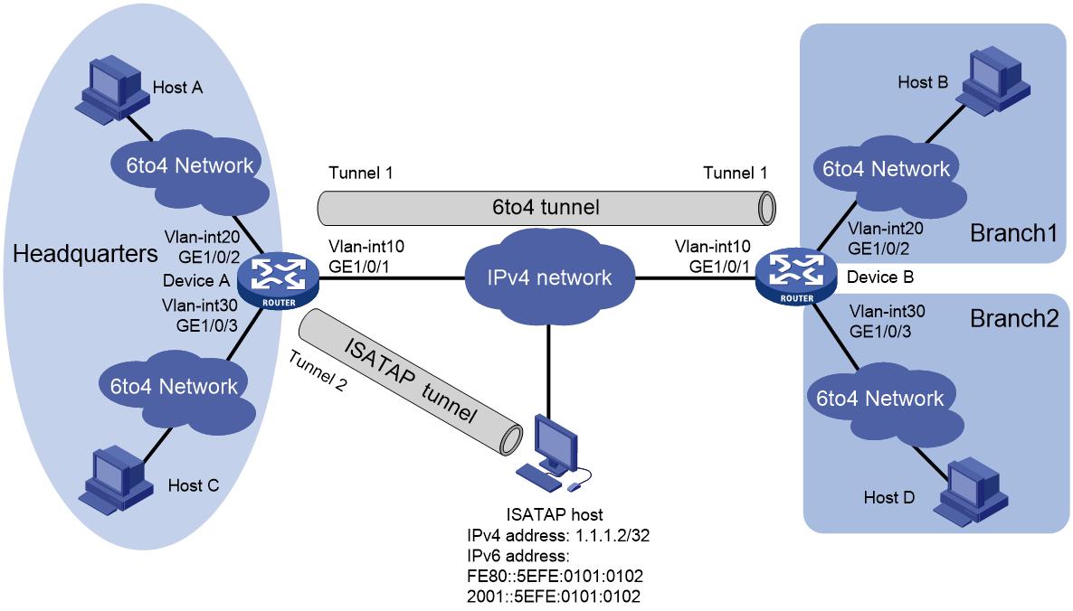
Table 1 Interface and IP address assignment
|
Device |
Interface |
IP address |
Device |
Interface |
IP address |
|
Device A |
Vlan-int10 |
2.1.1.1/24 |
Device B |
Vlan-int10 |
3.1.1.1/24 |
|
|
Vlan-int20 |
2002:0201:0101:1::1/64 |
|
Vlan-int20 |
2002:0301:0101:1::1/64 |
|
|
Vlan-int30 |
2002:0201:0101:2::1/64 |
|
Vlan-int30 |
2002:0301:0101:2::1/64 |
|
|
Tunnel 1 |
3001::1/64 |
|
Tunnel 1 |
3001::2/64 |
|
|
Tunnel 2 |
2001::5EFE:0201:0101/64 |
|
|
|
Applicable hardware and software versions
The following matrix shows the hardware and software versions to which this configuration example is applicable:
|
Hardware |
Software version |
|
S6812 switch series S6813 switch series |
Release 63xx |
|
S6550XE-HI switch series |
Release 6008 and later |
|
S6525XE-HI switch series |
Release 6008 and later |
|
S5850 switch series |
Release 8005 and later |
|
S5570S-EI switch series |
Not supported |
|
S5560X-EI switch series |
Release 63xx, Release 65xx |
|
S5560X-HI switch series |
Release 63xx, Release 65xx |
|
S5500V2-EI switch series |
Release 63xx, Release 65xx |
|
ES5500 switch series |
Release 63xx, Release 65xx |
|
MS4520V2-30F switch MS4520V2-30C switch MS4520V2-54C switch |
Release 63xx, Release 65xx |
|
S6520X-HI switch series S6520X-EI switch series |
Release 63xx, Release 65xx |
|
S6520X-SI switch series S6520-SI switch series |
Release 63xx, Release 65xx |
|
S5000-EI switch series |
Release 63xx, Release 65xx |
|
MS4600 switch series |
Release 63xx, Release 65xx |
|
S5500V3-SI switch series (except S5500V3-24P-SI and S5500V3-48P-SI switches) |
Not supported |
|
S5170-EI switch series |
Not supported |
|
S5120V3-EI switch series |
Not supported |
|
S5120V3-36F-SI switch S5120V3-28P-HPWR-SI switch S5120V3-54P-PWR-SI switch |
Not supported |
|
S3600V3-EI switch series |
Not supported |
|
S3600V3-SI switch series |
Not supported |
Restrictions and guidelines
When you configure an ISATAP tunnel and a 6to4 tunnel, follow these restrictions and guidelines:
· You do not need to configure a destination address for a 6to4 tunnel, because the destination IPv4 address is embedded in the 6to4 IPv6 address whose format is 2002:IPv4-destination-address::/64.
· You do not need to configure a destination address for an ISATAP tunnel, because the destination IPv4 address is embedded in the ISATAP address whose format is Prefix:0:5EFE:IPv4-destination-address.
· Disable RA suppression on Device A and Device B to allow hosts to acquire address prefixes automatically. This configuration ensures that hosts in the same network use the same address prefix.
After RA suppression is disabled, the ISATAP host and hosts in the headquarters acquire address prefixes from RA messages advertised by Device A. Hosts in the branches acquire address prefixes from RA messages advertised by Device B.
Procedures
Make sure Device A and Device B can reach each other through IPv4.
Configuring Device A
# Configure an IP address for VLAN-interface 10.
<DeviceA> system-view
[DeviceA] vlan 10
[DeviceA-vlan10] port GigabitEthernet 1/0/1
[DeviceA-vlan10] quit
[DeviceA] interface vlan-interface 10
[DeviceA-Vlan-interface10] ip address 2.1.1.1 24
[DeviceA-Vlan-interface10] quit
# Configure IP addresses for other interfaces as shown in Table 1. (Details not shown.)
# Create service loopback group 1 and specify tunnel services for the group, and then add GigabitEthernet 1/0/4 to the group. (This step is required for the S6550XE-HI, S6525XE-HI, and S5850 switch series to receive and send tunnel packets.)
[DeviceA] service-loopback group 1 type tunnel
[DeviceA] interface gigabitethernet 1/0/4
[DeviceA-GigabitEthernet1/0/4] port service-loopback group 1
[DeviceA-GigabitEthernet1/0/4] quit
# Create a 6to4 tunnel interface Tunnel 1.
[DeviceA] interface tunnel 1 mode ipv6-ipv4 6to4
# Specify an IPv6 address for the tunnel interface.
[DeviceA-Tunnel1] ipv6 address 3001::1/64
# Specify the source interface as VLAN-interface 10 for the tunnel interface.
[DeviceA-Tunnel1] source vlan-interface 10
[DeviceA-Tunnel1] quit
# Configure a static route destined for 2002:0301:0101::/48 through the tunnel interface.
[DeviceA] ipv6 route-static 2002:0301:0101:: 48 tunnel 1
# Create an ISATAP tunnel interface Tunnel 2.
[DeviceA] interface tunnel 2 mode ipv6-ipv4 isatap
# Specify an IPv6 address for the tunnel interface.
[DeviceA-Tunnel2] ipv6 address 2001::5EFE:0201:0101 64
# Specify the source interface as VLAN-interface 10 for the tunnel interface.
[DeviceA-Tunnel2] source vlan-interface 10
[DeviceA-Tunnel2] quit
# Configure a static route destined for 2001::/16 through the tunnel interface.
[DeviceA] ipv6 route-static 2001:: 16 tunnel 2
# Disable RA suppression.
[DeviceA] interface Tunnel 2
[DeviceA-Tunnel2] undo ipv6 nd ra halt
[DeviceA-Tunnel2] quit
[DeviceA] interface vlan-interface 20
[DeviceA-Vlan-interface20] undo ipv6 nd ra halt
[DeviceA-Vlan-interface20] quit
[DeviceA] interface vlan-interface 30
[DeviceA-Vlan-interface30] undo ipv6 nd ra halt
[DeviceA-Vlan-interface30] quit
Configuring Device B
# Configure an IP address for VLAN-interface 10.
<DeviceB> system-view
[DeviceB] vlan 10
[DeviceB-vlan10] port GigabitEthernet 1/0/1
[DeviceB-vlan10] quit
[DeviceB] interface vlan-interface 10
[DeviceB-Vlan-interface10] ip address 3.1.1.1 24
[DeviceB-Vlan-interface10] quit
# Configure IP addresses for other interfaces as shown in Table 1. (Details not shown.)
# Create service loopback group 1 and specify tunnel services for the group, and then add GigabitEthernet 1/0/4 to the group. (This step is required for the S6550XE-HI, S6525XE-HI, and S5850 switch series to receive and send tunnel packets.)
[DeviceB] service-loopback group 1 type tunnel
[DeviceB] interface gigabitethernet 1/0/4
[DeviceB-GigabitEthernet1/0/4] port service-loopback group 1
[DeviceB-GigabitEthernet1/0/4] quit
# Create a 6to4 tunnel interface Tunnel 1.
[DeviceB] interface tunnel 1 mode ipv6-ipv4 6to4
# Specify an IPv6 address for the tunnel interface.
[DeviceB-Tunnel1] ipv6 address 3001::2/64
# Specify the source interface as VLAN-interface 10 for the tunnel interface.
[DeviceB-Tunnel1] source vlan-interface 10
[DeviceB-Tunnel1] quit
# Configure a static route destined for 2002:0201:0101::/48 through the tunnel interface.
[DeviceB] ipv6 route-static 2002:0201:0101:: 48 tunnel 1
# Disable RA suppression.
[DeviceB] interface vlan-interface 20
[DeviceB-Vlan-interface20] undo ipv6 nd ra halt
[DeviceB-Vlan-interface20] quit
[DeviceB] interface vlan-interface 30
[DeviceB-Vlan-interface30] undo ipv6 nd ra halt
[DeviceB-Vlan-interface30] quit
Configuring the ISATAP host
Configurations on the ISATAP host vary by operating system. The following example is performed on Windows XP.
# Install IPv6.
C:\>ipv6 install
# Configure an ISATAP tunnel.
C:\>netsh interface ipv6 isatap set router 2.1.1.1
# Display information about the ISATAP tunnel interface.
C:\>ipv6 if 2
Interface 2: Automatic Tunneling Pseudo-Interface
Guid {48FCE3FC-EC30-E50E-F1A7-71172AEEE3AE}
does not use Neighbor Discovery
uses Router Discovery
routing preference 1
EUI-64 embedded IPv4 address: 1.1.1.2
router link-layer address: 2.1.1.1
preferred global 2001::5efe:1.1.1.2, life 29d23h59m46s/6d23h59m46s (public)
preferred link-local fe80::5efe:1.1.1.2, life infinite
link MTU 1500 (true link MTU 65515)
current hop limit 255
reachable time 42500ms (base 30000ms)
retransmission interval 1000ms
DAD transmits 0
default site prefix length 48
The host has acquired the prefix 2001::/64 and has automatically generated the global unicast address 2001::5efe:1.1.1.2. The message "uses Router Discovery" indicates that the router discovery function is enabled on the host.
# Display information about IPv6 routes on the host.
C:\>ipv6 rt
2001::/64 -> 2 pref 1if+8=9 life 29d23h59m43s (autoconf)
::/0 -> 2/fe80::5efe:1.1.1.1 pref 1if+256=257 life 29m43s (autoconf)
Verifying the configuration
# Verify that Host A and Host B can ping each other.
D:\>ping6 -s 2002:0201:0101:1::2 2002:0301:0101:1::2
Pinging 2002:0301:0101:1::2
from 2002:0201:0101:1::2 with 32 bytes of data:
Reply from 2002:0301:0101:1::2: bytes=32 time=13ms
Reply from 2002:0301:0101:1::2: bytes=32 time=1ms
Reply from 2002:0301:0101:1::2: bytes=32 time=1ms
Reply from 2002:0301:0101:1::2: bytes=32 time<1ms
Ping statistics for 2002:0301:0101:1::2:
Packets: Sent = 4, Received = 4, Lost = 0 (0% loss),
Approximate round trip times in milli-seconds:
Minimum = 0ms, Maximum = 13ms, Average = 3ms
# Verify that the ISATAP host can ping Host A.
C:\Documents and Settings\Administrator>pingv6 2002:0201:0101:1::2
Pinging 2002:0201:0101:1::2 with 32 bytes of data:
Reply from 2002:0201:0101:1::2: time=33ms
Reply from 2002:0201:0101:1::2: time=32ms
Reply from 2002:0201:0101:1::2: time=32ms
Reply from 2002:0201:0101:1::2: time=33ms
Ping statistics for 2002:0201:0101:1::2:
Packets: Sent = 4, Received = 4, Lost = 0 (0% loss),
Approximate round trip times in milli-seconds:
Minimum = 32ms, Maximum = 33ms, Average = 32ms
Configuration files
· Device A:
#
service-loopback group 1 type tunnel
#
vlan 10
#
vlan 20
#
vlan 30
#
interface Vlan-interface10
ip address 2.1.1.1 255.255.255.0
#
interface Vlan-interface20
ipv6 address 2002:201:101:1::1/64
undo ipv6 nd ra halt
#
interface Vlan-interface30
ipv6 address 2002:201:101:2::1/64
undo ipv6 nd ra halt
#
interface GigabitEthernet1/0/1
port link-mode bridge
port access vlan 10
#
interface GigabitEthernet1/0/2
port link-mode bridge
port access vlan 20
#
interface GigabitEthernet1/0/3
port link-mode bridge
port access vlan 30
#
interface GigabitEthernet1/0/4
port link-mode bridge
port service-loopback group 1
#
interface Tunnel1 mode ipv6-ipv4 6to4
source Vlan-interface10
ipv6 address 3001::1/64
#
interface Tunnel2 mode ipv6-ipv4 isatap
source Vlan-interface10
ipv6 address 2001::5EFE:201:101/64
undo ipv6 nd ra halt
#
ipv6 route-static 2001:: 16 Tunnel2
ipv6 route-static 2002:301:101:: 48 Tunnel1
#
· Device B:
#
service-loopback group 1 type tunnel
#
vlan 10
#
vlan 20
#
vlan 30
#
interface Vlan-interface10
ip address 3.1.1.1 255.255.255.0
#
interface Vlan-interface20
ipv6 address 2002:301:101:1::1/64
undo ipv6 nd ra halt
#
interface Vlan-interface30
ipv6 address 2002:301:101:2::1/64
undo ipv6 nd ra halt
#
interface GigabitEthernet1/0/1
port link-mode bridge
port access vlan 10
#
interface GigabitEthernet1/0/2
port link-mode bridge
port access vlan 20
#
interface GigabitEthernet1/0/3
port link-mode bridge
port access vlan 30
#
interface GigabitEthernet1/0/4
port link-mode bridge
port service-loopback group 1
#
interface Tunnel1 mode ipv6-ipv4 6to4
source Vlan-interface10
ipv6 address 3001::2/64
#
ipv6 route-static 2002:201:101:: 48 Tunnel1
#
