- Table of Contents
-
- H3C Fixed Port Campus Switches Configuration Examples-6W103
- 00-Applicable hardware and software versions
- 01-Login Management Configuration Examples
- 02-RBAC Configuration Examples
- 03-Software Upgrade Examples
- 04-ISSU Configuration Examples
- 05-Software Patching Examples
- 06-Ethernet Link Aggregation Configuration Examples
- 07-Port Isolation Configuration Examples
- 08-Spanning Tree Configuration Examples
- 09-VLAN Configuration Examples
- 10-VLAN Tagging Configuration Examples
- 11-DHCP Snooping Configuration Examples
- 12-Cross-Subnet Dynamic IP Address Allocation Configuration Examples
- 13-IPv6 over IPv4 Tunneling with OSPFv3 Configuration Examples
- 14-IPv6 over IPv4 GRE Tunnel Configuration Examples
- 15-GRE with OSPF Configuration Examples
- 16-OSPF Configuration Examples
- 17-IS-IS Configuration Examples
- 18-BGP Configuration Examples
- 19-Policy-Based Routing Configuration Examples
- 20-OSPFv3 Configuration Examples
- 21-IPv6 IS-IS Configuration Examples
- 22-Routing Policy Configuration Examples
- 23-IGMP Snooping Configuration Examples
- 24-IGMP Configuration Examples
- 25-MLD Snooping Configuration Examples
- 26-IPv6 Multicast VLAN Configuration Examples
- 27-ACL Configuration Examples
- 28-Traffic Policing Configuration Examples
- 29-GTS and Rate Limiting Configuration Examples
- 30-Traffic Filtering Configuration Examples
- 31-AAA Configuration Examples
- 32-Port Security Configuration Examples
- 33-Portal Configuration Examples
- 34-SSH Configuration Examples
- 35-IP Source Guard Configuration Examples
- 36-Ethernet OAM Configuration Examples
- 37-CFD Configuration Examples
- 38-DLDP Configuration Examples
- 39-VRRP Configuration Examples
- 40-BFD Configuration Examples
- 41-NTP Configuration Examples
- 42-SNMP Configuration Examples
- 43-NQA Configuration Examples
- 44-Mirroring Configuration Examples
- 45-sFlow Configuration Examples
- 46-OpenFlow Configuration Examples
- 47-MAC Address Table Configuration Examples
- 48-Static Multicast MAC Address Entry Configuration Examples
- 49-IP Unnumbered Configuration Examples
- 50-MVRP Configuration Examples
- 51-MCE Configuration Examples
- 52-Attack Protection Configuration Examples
- 53-Smart Link Configuration Examples
- 54-RRPP Configuration Examples
- 55-BGP Route Selection Configuration Examples
- 56-IS-IS Route Summarization Configuration Examples
- 57-VXLAN Configuration Examples
- 58-DRNI Configuration Examples
- 59-IRF 3.1 Configuration Examples
- 60-PTP Configuration Examples
- 61-S-MLAG Configuration Examples
- 62-Puppet Configuration Examples
- 63-802.1X Configuration Examples
- 64-MAC Authentication Configuration Examples
- 65-ISATAP Tunnel and 6to4 Tunnel Configuration Examples
- 66-BIDIR-PIM Configuration Examples
- 67-Congestion Avoidance and Queue Scheduling Configuration Examples
- 68-Basic MPLS Configuration Examples
- 69-MPLS L3VPN Configuration Examples
- 70-MPLS OAM Configuration Examples
- 71-EVPN-DCI over an MPLS L3VPN Network Configuration Examples
- 72-DRNI and EVPN Configuration Examples
- 73-Multicast VPN Configuration Examples
- 74-MPLS TE Configuration Examples
- 75-Control Plane-Based QoS Policy Configuration Examples
- 76-Priority Mapping and Queue Scheduling Configuration Examples
- 77-ARP Attack Protection Configuration Examples
- 78-IRF Software Upgrade Configuration Examples
- 79-IRF Member Replacement Configuration Examples
- 80-Layer 3 Multicast on Multicast Source-Side DR System Configuration Examples
- 81-EVPN Multicast Configuration Examples
- Related Documents
-
| Title | Size | Download |
|---|---|---|
| 63-802.1X Configuration Examples | 1.17 MB |
Contents
Example: Configuring local 802.1X authentication
Applicable hardware and software versions
Example: Configuring RADIUS-based 802.1X authentication (an H3C device acts as the RADIUS server)
Applicable hardware and software versions
Configuring the RADIUS server (Device B)
Configuring the NAS (Device A)
Example: Configuring 802.1X unicast trigger
Applicable hardware and software versions
Example: Configuring 802.1X with guest VLAN and authorization VLAN assignment
Applicable hardware and software versions
Example: Configuring 802.1X with ACL assignment
Applicable hardware and software versions
Introduction
The following information provides examples for configuring 802.1X authentication to ensure network access security.
Prerequisites
The configuration examples were created and verified in a lab environment, and all the devices were started with the factory default configuration. When you are working on a live network, make sure you understand the potential impact of every command on your network.
The following information is provided based on the assumption that you have basic knowledge of 802.1X.
Example: Configuring local 802.1X authentication
Network configuration
As shown in Figure 1, the device performs local 802.1X authentication on GigabitEthernet 1/0/1 to control Internet access of users. The interface performs port-based access control for 802.1X authentication.

Analysis
For the device to authenticate the 802.1X user on the host, add the 802.1X username and password to the device.
Applicable hardware and software versions
The following matrix shows the hardware and software versions to which this configuration example is applicable:
|
Hardware |
Software version |
|
S6812 switch series S6813 switch series |
Release 66xx |
|
S6550XE-HI switch series |
Release 6008 and later |
|
S6525XE-HI switch series |
Release 6008 and later |
|
S5850 switch series |
Release 8005 and later |
|
S5570S-EI switch series |
Release 11xx |
|
S5560X-EI switch series |
Release 63xx, Release 65xx, Release 66xx |
|
S5560X-HI switch series |
Release 63xx, Release 65xx, Release 66xx |
|
S5500V2-EI switch series |
Release 63xx, Release 65xx, Release 66xx |
|
MS4520V2-30F switch |
Release 63xx, Release 65xx, Release 66xx |
|
MS4520V2-30C switch MS4520V2-54C switch |
Release 65xx, Release 66xx |
|
MS4520V2-28S switch MS4520V2-24TP switch |
Release 63xx |
|
S6520X-HI switch series S6520X-EI switch series |
Release 63xx, Release 65xx, Release 66xx |
|
S6520X-SI switch series S6520-SI switch series |
Release 63xx, Release 65xx, Release 66xx |
|
S5000-EI switch series |
Release 63xx, Release 65xx, Release 66xx |
|
MS4600 switch series |
Release 63xx, Release 65xx, Release 66xx |
|
ES5500 switch series |
Release 63xx, Release 65xx, Release 66xx |
|
S5560S-EI switch series S5560S-SI switch series |
Release 63xx |
|
S5500V3-24P-SI switch S5500V3-48P-SI switch |
Release 63xx |
|
S5500V3-SI switch series (except the S5500V3-24P-SI and S5500V3-48P-SI switches) |
Release 11xx |
|
S5170-EI switch series |
Release 11xx |
|
S5130S-HI switch series S5130S-EI switch series S5130S-SI switch series S5130S-LI switch series |
Release 63xx |
|
S5120V2-SI switch series S5120V2-LI switch series |
Release 63xx |
|
S5120V3-EI switch series |
Release 11xx |
|
S5120V3-36F-SI switch S5120V3-28P-HPWR-SI switch S5120V3-54P-PWR-SI switch |
Release 11xx |
|
S5120V3-SI switch series (except the S5120V3-36F-SI, S5120V3-28P-HPWR-SI, and S5120V3-54P-PWR-SI switches) |
Release 63xx |
|
S5120V3-LI switch series |
Release 63xx |
|
S3600V3-EI switch series |
Release 11xx |
|
S3600V3-SI switch series |
Release 11xx |
|
S3100V3-EI switch series S3100V3-SI switch series |
Release 63xx |
|
S5110V2 switch series |
Release 63xx |
|
S5110V2-SI switch series |
Release 63xx |
|
S5000V3-EI switch series S5000V5-EI switch series |
Release 63xx |
|
S5000E-X switch series S5000X-EI switch series |
Release 63xx |
|
E128C switch E152C switch E500C switch series E500D switch series |
Release 63xx |
|
MS4320V2 switch series MS4320V3 switch series MS4300V2 switch series MS4320 switch series MS4200 switch series |
Release 63xx |
|
WS5850-WiNet switch series |
Release 63xx |
|
WS5820-WiNet switch series WS5810-WiNet switch series |
Release 63xx |
|
WAS6000 switch series |
Release 63xx |
|
IE4300-12P-AC switch IE4300-12P-PWR switch IE4300-M switch series IE4320 switch series |
Release 63xx |
Restrictions and guidelines
As a best practice to avoid valid users from being blocked, do not enable 802.1X globally before you finish all settings.
802.1X settings take effect on an interface only when 802.1X is enabled both globally and on the interface.
Procedures
Configuring the device
1. Configure a local user:
# Add a network access user named dot1x and enter its view.
<Device> system-view
[Device] local-user dot1x class network
New local user added.
# Set the user password to 123456TESTplat&! in plaintext form.
[Device-luser-network-dot1x] password simple 123456TESTplat&!
# Allow the user to use the LAN access service.
[Device-luser-network-dot1x] service-type lan-access
[Device-luser-network-dot1x] quit
2. Create VLAN-interface 1 and assign an IP address to the VLAN interface. The VLAN interface will be the gateway of the host.
[Device] interface vlan-interface 1
[Device-Vlan-interface1] ip address 192.168.56.101 255.255.255.0
[Device-Vlan-interface1] quit
3. Configure 802.1X authentication:
# Enable 802.1X on interface GigabitEthernet 1/0/1.
[Device] interface gigabitethernet1/0/1
[Device-GigabitEthernet1/0/1] dot1x
# Enable port-based access control.
[Device-GigabitEthernet1/0/1] dot1x port-method portbased
[Device-GigabitEthernet1/0/1] quit
# Enable 802.1X globally.
[Device] dot1x
Configuring the 802.1X client
Restrictions and guidelines
This example uses iNode PC 7.3 (E0518) to describe the procedure.
If the host runs the Windows XP built-in 802.1X client, configure the network connection properties as follows:
1. Click the Authentication tab of the properties window.
2. Select the Enable IEEE 802.1X authentication for this network option.
3. Select MD5 challenge as the EAP type.
4. Click OK.
Make sure the client can update its IP address to access the resources in the authorized VLAN after passing authentication.
Procedure
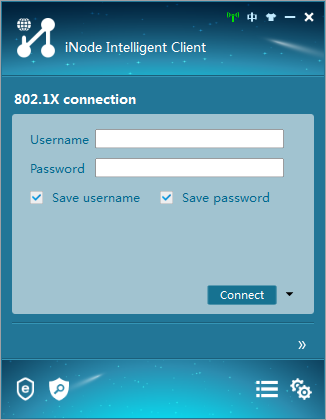
1. Run the iNode client.
Figure 2 iNode client
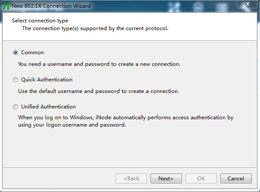
2. Create a new 802.1X connection.
3. On the New 802.1X Connection Wizard window, select Common, and then click Next.
Figure 3 Creating an 802.1X connection
4. Enter the 802.1X connection name, username, and password, and then click Next.
Figure 4 Configuring the 802.1X connection name, username, and password

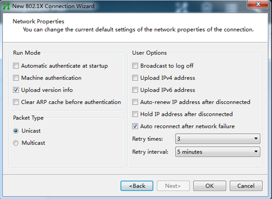
5. Configure the network property settings, and then click OK.
Do not select Upload version info in the Run Mode area. The device cannot recognize the version number in EAP packets.
Figure 5 Configuring 802.1X connection properties
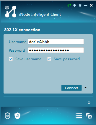
6. Initiate the 802.1X connection.
Enter the username and password on the iNode client, and then click Connect.
Figure 6 Initiating the 802.1X connection
Verifying the configuration
|
|
IMPORTANT: Support for VSI-related fields depends on the device model. |
# Display 802.1X information on interface GigabitEthernet 1/0/1.
[Device] display dot1x interface gigabitethernet 1/0/1
Global 802.1X parameters:
802.1X authentication : Enabled
CHAP authentication : Enabled
Max-tx period : 30 s
Handshake period : 15 s
Offline detect period : 300 s
Quiet timer : Disabled
Quiet period : 60 s
Supp timeout : 30 s
Server timeout : 100 s
Reauth period : 3600 s
Max auth requests : 2
User aging period for Auth-Fail VLAN : 1000 s
User aging period for Auth-Fail VSI : 1000 s
User aging period for critical VLAN : 1000 s
User aging period for critical VSI : 1000 s
User aging period for guest VLAN : 1000 s
User aging period for guest VSI : 1000 s
EAD assistant function : Disabled
EAD timeout : 30 min
Domain delimiter : @
Online 802.1X wired users : 0
GigabitEthernet1/0/1 is link-up
802.1X authentication : Enabled
Handshake : Enabled
Handshake reply : Disabled
Handshake security : Disabled
Unicast trigger : Disabled
Periodic reauth : Disabled
Port role : Authenticator
Authorization mode : Auto
Port access control : Port-based
Multicast trigger : Enabled
Mandatory auth domain : Not configured
Guest VLAN : Not configured
Auth-Fail VLAN : Not configured
Critical VLAN : Not configured
Critical voice VLAN : Disabled
Add Guest VLAN delay : Disabled
Re-auth server-unreachable : Logoff
Max online users : 4294967295
User IP freezing : Disabled
Reauth period : 0 s
Send Packets Without Tag : Disabled
Max Attempts Fail Number : 0
Guest VSI : Not configured
Auth-Fail VSI : Not configured
Critical VSI : Not configured
Add Guest VSI delay : Disabled
User aging : Enabled
Server-recovery online-user-sync : Disabled
Auth-Fail EAPOL : Disabled
Critical EAPOL : Disabled
Discard duplicate EAPOL-Start : No
EAPOL packets: Tx 0, Rx 0
Sent EAP Request/Identity packets : 0
EAP Request/Challenge packets: 0
EAP Success packets: 0
EAP Failure packets: 0
Received EAPOL Start packets : 0
EAPOL LogOff packets: 0
EAP Response/Identity packets : 0
EAP Response/Challenge packets: 0
Error packets: 0
Online 802.1X users: 0
# After the user passes authentication, display online 802.1X user information.
[Device] display dot1x connection
Configuration files
#
interface Vlan-interface1
ip address 192.168.56.101 255.255.255.0
#
local-user localuser class network
password cipher $c$3$YPkufRcxFR3KdpUCHFiNkns/YFPmbJkG/pQxBg==
service-type lan-access
authorization-attribute user-role network-operator
#
interface GigabitEthernet1/0/1
dot1x
dot1x port-method portbased
#
dot1x
#
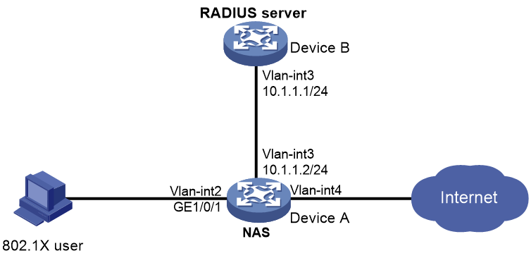
Example: Configuring RADIUS-based 802.1X authentication (an H3C device acts as the RADIUS server)
Network configuration
As shown in Figure 7, Device B acts as the RADIUS server to provide authentication and authorization services for the 802.1X user connected to Device A (the NAS).
After the user passes authentication, the RADIUS server assigns VLAN 4 to GigabitEthernet 1/0/1 (the NAS port that the user is connecting to).
Analysis
· For the RADIUS server to authenticate the 802.1X user, perform the following tasks on the RADIUS server:
a. Add the device to the RADIUS server as a RADIUS client.
b. Add the 802.1X username and password to the RADIUS server.
· For the user to access resources in VLAN 4 after it passes authentication, specify VLAN 4 as the authorization VLAN for the user on the RADIUS server.
· To ensure secure transmission between the RADIUS server and device and avoid RADIUS packets from being tampered with, configure the same shared key on the RADIUS server and device.
· To use the RADIUS server for authentication and authorization, perform the following tasks on the device:
c. Create a RADIUS scheme.
d. Specify the RADIUS server as the authentication and authorization server in the RADIUS scheme.
e. Apply the RADIUS scheme to the ISP domain of the 802.1X user.
Applicable hardware and software versions
The following matrix shows the hardware and software versions to which this configuration example is applicable:
|
Hardware |
Software versions |
|
S6812 switch series S6813 switch series |
Release 66xx |
|
S6550XE-HI switch series |
Release 6008 and later |
|
S6525XE-HI switch series |
Release 6008 and later |
|
S5850 switch series |
Release 8005 and later |
|
S5570S-EI switch series |
Release 11xx |
|
S5560X-EI switch series |
Release 63xx, Release 65xx, Release 66xx |
|
S5560X-HI switch series |
Release 63xx, Release 65xx, Release 66xx |
|
S5500V2-EI switch series |
Release 63xx, Release 65xx, Release 66xx |
|
MS4520V2-30F switch |
Release 63xx, Release 65xx, Release 66xx |
|
MS4520V2-30C switch MS4520V2-54C switch |
Release 65xx, Release 66xx |
|
MS4520V2-28S switch MS4520V2-24TP switch |
Release 63xx |
|
S6520X-HI switch series S6520X-EI switch series |
Release 63xx, Release 65xx, Release 66xx |
|
S6520X-SI switch series S6520-SI switch series |
Release 63xx, Release 65xx, Release 66xx |
|
S5000-EI switch series |
Release 63xx, Release 65xx, Release 66xx |
|
MS4600 switch series |
Release 63xx, Release 65xx, Release 66xx |
|
ES5500 switch series |
Release 63xx, Release 65xx, Release 66xx |
|
S5560S-EI switch series S5560S-SI switch series |
Release 63xx |
|
S5500V3-24P-SI switch S5500V3-48P-SI switch |
Release 63xx |
|
S5500V3-SI switch series (except the S5500V3-24P-SI and S5500V3-48P-SI switches) |
Release 11xx |
|
S5170-EI switch series |
Release 11xx |
|
S5130S-HI switch series S5130S-EI switch series S5130S-SI switch series S5130S-LI switch series |
Release 63xx |
|
S5120V2-SI switch series S5120V2-LI switch series |
Release 63xx |
|
S5120V3-EI switch series |
Release 11xx |
|
S5120V3-36F-SI switch S5120V3-28P-HPWR-SI switch S5120V3-54P-PWR-SI switch |
Release 11xx |
|
S5120V3-SI switch series (except the S5120V3-36F-SI, S5120V3-28P-HPWR-SI, and S5120V3-54P-PWR-SI switches) |
Release 63xx |
|
S5120V3-LI switch series |
Release 63xx |
|
S3600V3-EI switch series |
Release 11xx |
|
S3600V3-SI switch series |
Release 11xx |
|
S3100V3-EI switch series S3100V3-SI switch series |
Release 63xx |
|
S5110V2 switch series |
Release 63xx |
|
S5110V2-SI switch series |
Release 63xx |
|
S5000V3-EI switch series S5000V5-EI switch series |
Release 63xx |
|
S5000E-X switch series S5000X-EI switch series |
Release 63xx |
|
E128C switch E152C switch E500C switch series E500D switch series |
Release 63xx |
|
MS4320V2 switch series MS4320V3 switch series MS4300V2 switch series MS4320 switch series MS4200 switch series |
Release 63xx |
|
WS5850-WiNet switch series |
Release 63xx |
|
WS5820-WiNet switch series WS5810-WiNet switch series |
Release 63xx |
|
WAS6000 switch series |
Release 63xx |
|
IE4300-12P-AC switch IE4300-12P-PWR switch IE4300-M switch series IE4320 switch series |
Release 63xx |
Restrictions and guidelines
As a best practice to avoid valid users from being blocked, do not enable 802.1X globally before you finish all settings.
802.1X settings take effect on an interface only when 802.1X is enabled both globally and on the interface.
Procedures
Configuring the RADIUS server (Device B)
In this example, an H3C switch acts as the RADIUS server.
# Create a network access user named dot1x and enter its view.
<DeviceB> system-view
[DeviceB] local-user dot1x class network
New local user added.
# Set the password to 123456TESTplat&! in plaintext form for user dot1x.
[DeviceB-luser-network-dot1x] password simple 123456TESTplat&!
# Specify VLAN 4 as the authorization VLAN.
[DeviceB-luser-network-dot1x] authorization-attribute vlan 4
[DeviceB-luser-network-dot1x] quit
# Specify the RADIUS client at 10.1.1.2 and set the shared key to expert in plaintext form.
[DeviceB] radius-server client ip 10.1.1.2 key simple expert
# Activate RADIUS client and user settings.
[DeviceB] radius-server activate
Configuring the NAS (Device A)
1. Configure a RADIUS scheme:
# Create a RADIUS scheme named rad and enter its view.
<DeviceA> system-view
[DeviceA] radius scheme rad
New RADIUS scheme.
# Specify the server at 10.1.1.1 as the primary authentication server, and set the shared key to expert in plain text for secure communication between the authentication server and the device.
[DeviceA-radius-rad] primary authentication 10.1.1.1 key simple expert
# Exclude the ISP domain name from the usernames sent to the RADIUS server.
[DeviceA-radius-rad] user-name-format without-domain
[DeviceA-radius-rad] quit
2. Configure an ISP domain:
# Create an ISP domain named bbb and enter its view.
[DeviceA] domain bbb
# Configure the ISP domain to use RADIUS scheme rad for LAN user authentication and authorization, and do not perform accounting for LAN users in the domain.
[DeviceA-isp-bbb] authentication lan-access radius-scheme rad
[DeviceA-isp-bbb] authorization lan-access radius-scheme rad
[DeviceA-isp-bbb] accounting lan-access none
[DeviceA-isp-bbb] quit
3. Configure 802.1X authentication:
# Enable 802.1X on interface GigabitEthernet 1/0/1.
[DeviceA] interface gigabitethernet1/0/1
[DeviceA-GigabitEthernet1/0/1] dot1x
# Specify ISP domain bbb as the mandatory authentication domain on interface GigabitEthernet 1/0/1.
[DeviceA-GigabitEthernet1/0/1] dot1x mandatory-domain bbb
[DeviceA-GigabitEthernet1/0/1] quit
# Enable 802.1X globally.
[DeviceA] dot1x
Configuring the 802.1X client
Restrictions and guidelines
This example uses iNode PC 7.3 (E0518) to describe the procedure.
If the host runs the Windows XP built-in 802.1X client, configure the network connection properties as follows:
1. Click the Authentication tab of the properties window.
2. Select the Enable IEEE 802.1X authentication for this network option.
3. Select MD5 challenge as the EAP type.
4. Click OK.
Make sure the client can update its IP address to access the resources in the authorized VLAN after passing authentication.
Procedure
1. Run the iNode client.
Figure 8 iNode client
2. Create a new 802.1X connection.
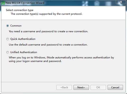
3. On the New 802.1X Connection Wizard window, select Common, and then click Next.
Figure 9 Creating a new 802.1X connection
4. Configure the connection name, username, and password, and then click Next.
Figure 10 Configuring the connection name, username, and password
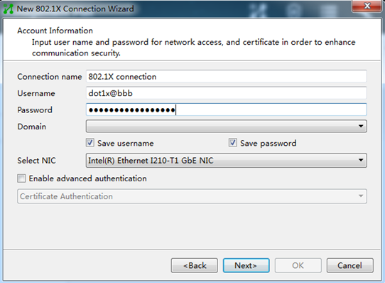
For authentication to be performed correctly, the following details must comply with the correlation rules shown in Table 1:
¡ Username specified on the iNode client.
¡ Domain and username format configuration on the access device.
¡ Service suffix on IMC.
|
Username format on the iNode client |
Domain on the access device |
Username format configured on the access device |
Service suffix on IMC |
|
X@Y |
Y |
with-domain |
Y |
|
X@Y |
Y |
without-domain |
No suffix |
|
X |
Default domain (the default domain specified on the access device) |
with-domain |
Name of the default domain |
|
X |
Default domain (the default domain specified on the access device) |
without-domain |
No suffix |
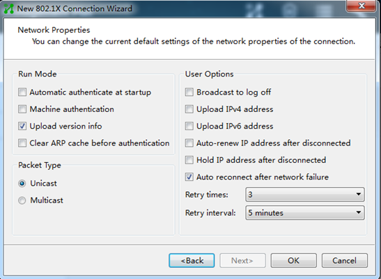
5. Configure the network property settings, and then click OK.
If you set local authentication as the backup authentication method, do not select Upload version info in the Run Mode area. The access device cannot recognize the version number in EAP packets.
Figure 11 Configuring 802.1X connection properties
6. Initiate the 802.1X connection.
Enter the username and password on the iNode client, and then click Connect.
Figure 12 Initiating the 802.1X connection
Verifying the configuration
|
|
IMPORTANT: Support for VSI-related fields depends on the device model. |
# On Device B, display all active RADIUS clients and RADIUS users.
[DeviceB] display radius-server active-client
Total 1 RADIUS clients.
Client IP: 10.1.1.2
[DeviceB] display radius-server active-user dot1x
Total 1 RADIUS users matched.
Username: dot1x
Description: Not configured
Authorization attributes:
VLAN ID: 4
ACL number: Not configured
Validity period:
Expiration time: Not configured
# On Device A, display online 802.1X user information.
[DeviceA] display dot1x connection
Total connections: 1
Slot ID: 1
User MAC address: 0010-9400-0021
Access interface: GigabitEthernet1/0/1
Username: dot1x@bbb
User access state: Successful
Authentication domain: bbb
EAP packet identifier: 4
Authentication method: CHAP
Initial VLAN: 2
Authorization untagged VLAN: N/A
Authorization tagged VLAN list: N/A
Authorization VSI: N/A
Authorization microsegment ID: N/A
Authorization ACL number/name: N/A
Authorization user profile: N/A
Authorization CAR: N/A
Authorization URL: N/A
Start accounting: Successful
Real-time accounting-update failures: 0
Termination action: Default
Session timeout period: 86400 s
Online from: 2013/01/20 07:58:10
Online duration: 0h 0m 40s
Configuration files
· Device A:
#
dot1x
#
radius scheme rad
primary authentication 10.1.1.1 key cipher $c$3$l+xIXR7hboPo33+MkEf/01WsnVHhxZCeYg==
user-name-format without-domain
#
domain bbb
authentication lan-access radius-scheme rad
authorization lan-access radius-scheme rad
accounting lan-access none
#
interface GigabitEthernet1/0/1
port link-mode bridge
dot1x
dot1x mandatory-domain bbb
#
· Device B:
#
local-user dot1x class network
password cipher $c$3$GuUyAQq0JHH6iBF38xsnB/tQEPTZhTAMIGLweOXr2uPbqJ0=
authorization-attribute vlan 4
authorization-attribute user-role network-operator
#
radius-server client ip 10.1.1.2 key cipher $c$3$Po5RD6PcGZi+V6l6Nx7hpiLZNSMeOjbUzQ==
#
radius-server activate
#
Example: Configuring 802.1X unicast trigger
Network configuration
As shown in Figure 13:
· The device uses the RADIUS server for 802.1X user authentication and authorization.
· IMC acts as the RADIUS server.
· The user on Host B uses the Windows XP built-in 802.1X client to interact with the device for 802.1X authentication.
Analysis
· For the device to use the RADIUS server for user authentication, perform the following tasks on the RADIUS server:
a. Add the device as an access device to the RADIUS server.
b. Add an access policy.
c. Add an access service and specify the access policy in the access service.
d. Add an access user and specify the access service for the access user.
· For the device to perform RADIUS-based authentication and authorization for the 802.1X user, configure AAA settings on the device, including ISP domain settings and RADIUS scheme settings.
· Because the Windows XP built-in 802.1X client cannot initiate 802.1X connection, you must enable an authentication trigger feature on the device. As a best practice to ensure system performance, disable 802.1X multicast trigger and enable unicast trigger. In multicast trigger mode, the device multicasts a large number of Identity EAP-Request packets periodically to the host, which consumes bandwidth and system resources.
Applicable hardware and software versions
The following matrix shows the hardware and software versions to which this configuration example is applicable:
|
Hardware |
Software versions |
|
S6812 switch series S6813 switch series |
Release 66xx |
|
S6550XE-HI switch series |
Release 6008 and later |
|
S6525XE-HI switch series |
Release 6008 and later |
|
S5850 switch series |
Release 8005 and later |
|
S5570S-EI switch series |
Release 11xx |
|
S5560X-EI switch series |
Release 63xx, Release 65xx, Release 66xx |
|
S5560X-HI switch series |
Release 63xx, Release 65xx, Release 66xx |
|
S5500V2-EI switch series |
Release 63xx, Release 65xx, Release 66xx |
|
MS4520V2-30F switch |
Release 63xx, Release 65xx, Release 66xx |
|
MS4520V2-30C switch MS4520V2-54C switch |
Release 65xx, Release 66xx |
|
MS4520V2-28S switch MS4520V2-24TP switch |
Release 63xx |
|
S6520X-HI switch series S6520X-EI switch series |
Release 63xx, Release 65xx, Release 66xx |
|
S6520X-SI switch series S6520-SI switch series |
Release 63xx, Release 65xx, Release 66xx |
|
S5000-EI switch series |
Release 63xx, Release 65xx, Release 66xx |
|
MS4600 switch series |
Release 63xx, Release 65xx, Release 66xx |
|
ES5500 switch series |
Release 63xx, Release 65xx, Release 66xx |
|
S5560S-EI switch series S5560S-SI switch series |
Release 63xx |
|
S5500V3-24P-SI switch S5500V3-48P-SI switch |
Release 63xx |
|
S5500V3-SI switch series (except the S5500V3-24P-SI and S5500V3-48P-SI switches) |
Release 11xx |
|
S5170-EI switch series |
Release 11xx |
|
S5130S-HI switch series S5130S-EI switch series S5130S-SI switch series S5130S-LI switch series |
Release 63xx |
|
S5120V2-SI switch series S5120V2-LI switch series |
Release 63xx |
|
S5120V3-EI switch series |
Release 11xx |
|
S5120V3-36F-SI switch S5120V3-28P-HPWR-SI switch S5120V3-54P-PWR-SI switch |
Release 11xx |
|
S5120V3-SI switch series (except the S5120V3-36F-SI, S5120V3-28P-HPWR-SI, and S5120V3-54P-PWR-SI switches) |
Release 63xx |
|
S5120V3-LI switch series |
Release 63xx |
|
S3600V3-EI switch series |
Release 11xx |
|
S3600V3-SI switch series |
Release 11xx |
|
S3100V3-EI switch series S3100V3-SI switch series |
Release 63xx |
|
S5110V2 switch series |
Release 63xx |
|
S5110V2-SI switch series |
Release 63xx |
|
S5000V3-EI switch series S5000V5-EI switch series |
Release 63xx |
|
S5000E-X switch series S5000X-EI switch series |
Release 63xx |
|
E128C switch E152C switch E500C switch series E500D switch series |
Release 63xx |
|
MS4320V2 switch series MS4320V3 switch series MS4300V2 switch series MS4320 switch series MS4200 switch series |
Release 63xx |
|
WS5850-WiNet switch series |
Release 63xx |
|
WS5820-WiNet switch series WS5810-WiNet switch series |
Release 63xx |
|
WAS6000 switch series |
Release 63xx |
|
IE4300-12P-AC switch IE4300-12P-PWR switch IE4300-M switch series IE4320 switch series |
Release 63xx |
Restrictions and guidelines
As a best practice to avoid duplicate authentication packets, disable multicast trigger on an interface if unicast trigger is enabled on that interface.
Prerequisites
Configure IP addresses for interfaces, as shown in Figure 13. Make sure the host, device, and server are reachable.
Procedures
Configuring the RADIUS server
This example uses IMC PLAT 7.3 (E0506), IMC EIA 7.3 (E0503), and IMC EIP 7.3 (E0503) to describe the procedure.
Adding the device to the IMC Platform as an access device
1. Log in to IMC.
2. Click the User tab.
3. From the navigation pane, select User Access Policy > Access Device Management > Access Device.
4. Click Add.
5. On the page that opens, configure access device parameters.
a. Set the ports for authentication and accounting to 1812 and 1813, respectively.
b. Set the shared key to expert for secure authentication and accounting communication, and confirm the shared key.
c. Select H3C (General) from the Access Device Type list.
d. Select an access device from the device list or manually add an access device. In this example, the device IP address is 10.1.1.2.
e. Use the default values for other parameters.
f. Click OK.
The IP address of the access device specified on the RADIUS server must be the same as the source IP address of the RADIUS packets sent from the device. On the device, the source IP address is chosen in the following order:
a. IP address specified by using the nas-ip command.
b. IP address specified by using the radius nas-ip command.
c. IP address of the outbound interface (the default).
In this example, the device uses the IP address of the outbound interface as the source IP address of RADIUS packets.
Figure 14 Adding an access device
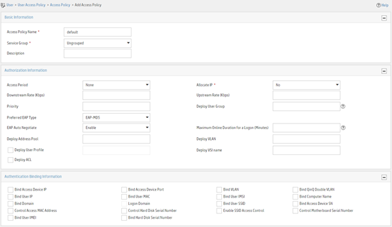
Adding an access policy
1. Click the User tab.
2. From the navigation pane, select User Access Policy > Access Policy.
3. Click Add.
4. On the page that opens, configure access policy parameters.
a. Enter access policy name default.
b. Use the default values for other parameters.
c. Click OK.
Figure 15 Adding an access policy
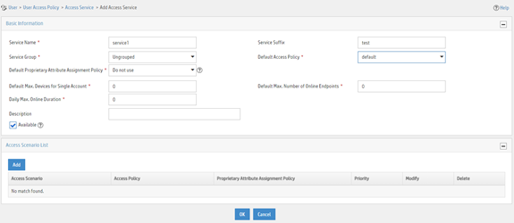
Adding an access service
1. Click the User tab.
2. From the navigation pane, select User Access Policy > Access Service.
3. Click Add.
4. On the page that opens, configure access service parameters.
a. Enter service name service1 and set the service suffix to test. The service suffix is the authentication domain for the 802.1X user.
|
|
IMPORTANT: With the service suffix configured, you must configure the device to send usernames that include the domain name to the RADIUS server. By default, the device includes the domain name in the usernames sent to a RADIUS server. |
b. Select default from the Default Access Policy list.
c. Use the default values for other parameters.
d. Click OK.
Figure 16 Adding an access service
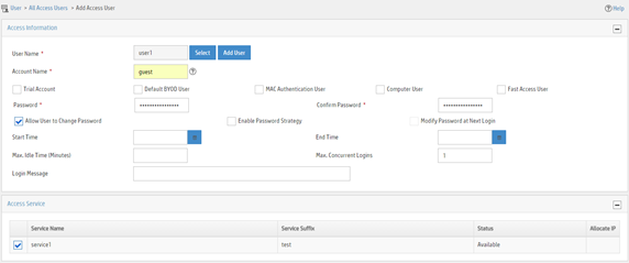
Adding an access user
1. Click the User tab.
2. From the navigation pane, select Access User > Access User.
3. Click Add.
4. On the page that opens, configure access user parameters.
a. Click Add User to add a user named user1.
b. Enter account name guest and password 123456TESTplat&!. The device uses the account name to identify the user when the user accesses the network.
c. Select service1 in the Access Service area.
d. Use the default values for other parameters.
e. Click OK.
Figure 17 Adding an access user
Configuring the device
# Create VLANs and VLAN interfaces, and assign IP addresses to interfaces. (Details not shown.)
# Create a RADIUS scheme named radius1 and enter its view.
<Device> system-view
[Device] radius scheme radius1
# Specify the RADIUS server at 10.1.1.1 as the primary authentication server.
[Device-radius-radius1] primary authentication 10.1.1.1
# Set the shared key to expert in plaintext form for secure communication with the RADIUS authentication server.
[Device-radius-radius1] key authentication simple expert
# Create an ISP domain named test and enter its view.
[Device] domain test
# Configure the ISP domain to use RADIUS scheme radius1 for LAN user authentication and authorization in the domain.
[Device-isp-test] authentication lan-access radius-scheme radius1
[Device-isp-test] authorization lan-access radius-scheme radius1
[Device-isp-test] quit
# Configure domain test as the default domain.
[Device] domain default enable test
# Disable 802.1X multicast trigger on interface GigabitEthernet 1/0/1.
[Device] interface gigabitEthernet 1/0/1
[Device-GigabitEthernet1/0/1] undo dot1x multicast-trigger
# Enable 802.1X unicast trigger on interface GigabitEthernet 1/0/1.
[Device-GigabitEthernet 1/0/1] dot1x unicast-trigger
# Enable 802.1X on interface GigabitEthernet 1/0/1.
[Device-GigabitEthernet1/0/1] dot1x
[Device-GigabitEthernet1/0/1] quit
# Enable 802.1X globally.
[Device] dot1x
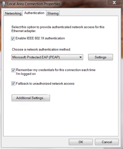
Configuring the 802.1X client
This example uses the Windows XP built-in 802.1X client to describe the procedure. The configuration is as shown in Figure 18.
Figure 18 Configuring the Windows XP built-in 802.1X client
Verifying the configuration
Verify that you can use the user account to pass 802.1X authentication:
# Use the host to visit an Internet webpage. The Windows status bar displays a message and asks you to enter your username and password.
# Enter username guest@test and password 123456TESTplat&!.
Configuration files
|
|
IMPORTANT: Support for the port link-mode bridge command depends on the device model. |
#
domain default enable test
#
dot1x
#
radius scheme radius1
primary authentication 10.1.1.1
key authentication cipher $c$3$LAV0oGNaM9Z/CuVcWONBH4xezu48Agh5aQ==
#
domain test
authentication default radius-scheme radius1
authorization default radius-scheme radius1
#
interface GigabitEthernet1/0/1
port link-mode bridge
undo dot1x multicast-trigger
dot1x
dot1x unicast-trigger
#
Example: Configuring 802.1X with guest VLAN and authorization VLAN assignment
Network configuration
As shown in Figure 19:
· Use a RADIUS server to perform authentication, authorization, and accounting for 802.1X users that connect to GigabitEthernet 1/0/2. Implement port-based access control on the port.
· Configure VLAN 10 as the 802.1X guest VLAN on GigabitEthernet 1/0/2. The host and the update server are both in VLAN 10, and the host can access the update server and download the 802.1X client software.
· To prevent users in the guest VLAN from accessing the Internet, apply a QoS policy to the outbound direction of VLAN 10 to filter packets destined for the Internet (5.1.1.1).
· After the host passes 802.1X authentication, the access device assigns the host to the same VLAN (VLAN 5) as the interface (GigabitEthernet 1/0/3) for Internet access.
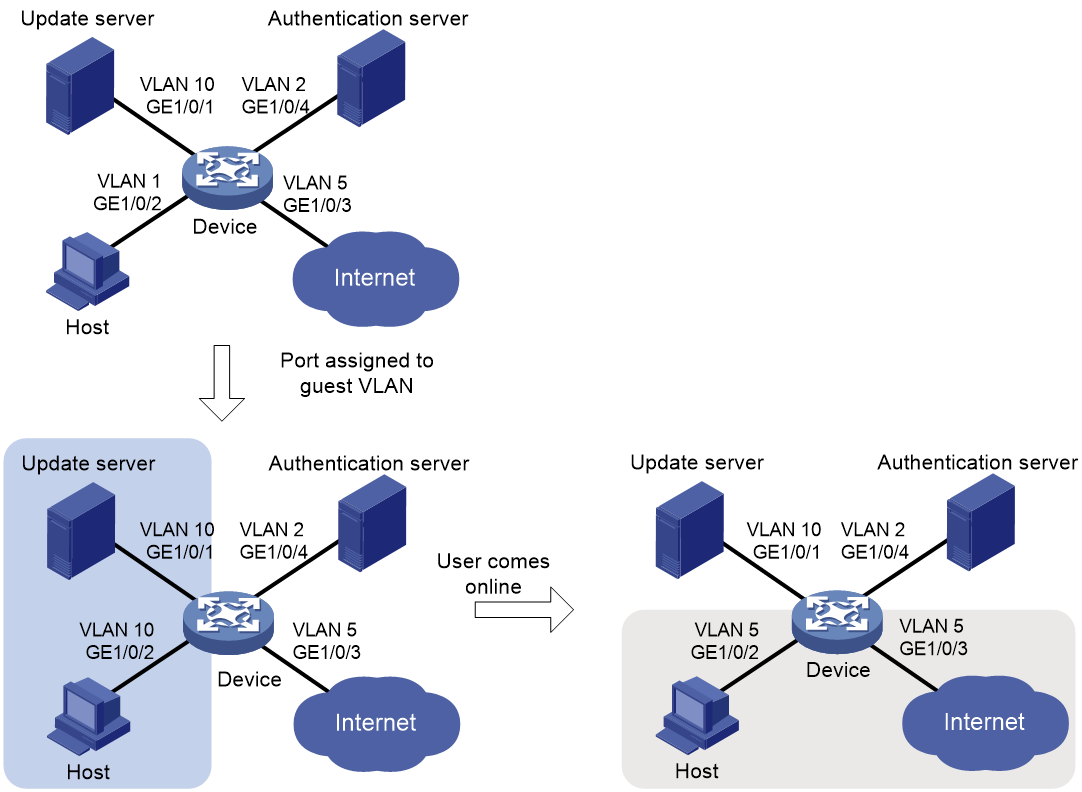
Analysis
· For the 802.1X user on the host to access the update server before it passes authentication, configure VLAN 10 as the guest VLAN on the port connected to the host.
· For the 802.1X user on the host to access the Internet after it passes authentication, specify VLAN 5 (the VLAN connected to the Internet) as the user's authorization VLAN. After the user passes 802.1X authentication, the port connected to the host is assigned to VLAN 5.
Applicable hardware and software versions
The following matrix shows the hardware and software versions to which this configuration example is applicable:
|
Hardware |
Software versions |
|
S6812 switch series S6813 switch series |
Release 66xx |
|
S6550XE-HI switch series |
Release 6008 and later |
|
S6525XE-HI switch series |
Release 6008 and later |
|
S5850 switch series |
Release 8005 and later |
|
S5570S-EI switch series |
Release 11xx |
|
S5560X-EI switch series |
Release 63xx, Release 65xx, Release 66xx |
|
S5560X-HI switch series |
Release 63xx, Release 65xx, Release 66xx |
|
S5500V2-EI switch series |
Release 63xx, Release 65xx, Release 66xx |
|
MS4520V2-30F switch |
Release 63xx, Release 65xx, Release 66xx |
|
MS4520V2-30C switch MS4520V2-54C switch |
Release 65xx, Release 66xx |
|
MS4520V2-28S switch MS4520V2-24TP switch |
Release 63xx |
|
S6520X-HI switch series S6520X-EI switch series |
Release 63xx, Release 65xx, Release 66xx |
|
S6520X-SI switch series S6520-SI switch series |
Release 63xx, Release 65xx, Release 66xx |
|
S5000-EI switch series |
Release 63xx, Release 65xx, Release 66xx |
|
MS4600 switch series |
Release 63xx, Release 65xx, Release 66xx |
|
ES5500 switch series |
Release 63xx, Release 65xx, Release 66xx |
|
S5560S-EI switch series S5560S-SI switch series |
Release 63xx |
|
S5500V3-24P-SI switch S5500V3-48P-SI switch |
Release 63xx |
|
S5500V3-SI switch series (except the S5500V3-24P-SI and S5500V3-48P-SI switches) |
Release 11xx |
|
S5170-EI switch series |
Release 11xx |
|
S5130S-HI switch series S5130S-EI switch series S5130S-SI switch series S5130S-LI switch series |
Release 63xx |
|
S5120V2-SI switch series S5120V2-LI switch series |
Release 63xx |
|
S5120V3-EI switch series |
Release 11xx |
|
S5120V3-36F-SI switch S5120V3-28P-HPWR-SI switch S5120V3-54P-PWR-SI switch |
Release 11xx |
|
S5120V3-SI switch series (except the S5120V3-36F-SI, S5120V3-28P-HPWR-SI, and S5120V3-54P-PWR-SI switches) |
Release 63xx |
|
S5120V3-LI switch series |
Release 63xx |
|
S3600V3-EI switch series |
Release 11xx |
|
S3600V3-SI switch series |
Release 11xx |
|
S3100V3-EI switch series S3100V3-SI switch series |
Release 63xx |
|
S5110V2 switch series |
Release 63xx |
|
S5110V2-SI switch series |
Release 63xx |
|
S5000V3-EI switch series S5000V5-EI switch series |
Release 63xx |
|
S5000E-X switch series S5000X-EI switch series |
Release 63xx |
|
E128C switch E152C switch E500C switch series E500D switch series |
Release 63xx |
|
MS4320V2 switch series MS4320V3 switch series MS4300V2 switch series MS4320 switch series MS4200 switch series |
Release 63xx |
|
WS5850-WiNet switch series |
Release 63xx |
|
WS5820-WiNet switch series WS5810-WiNet switch series |
Release 63xx |
|
WAS6000 switch series |
Release 63xx |
|
IE4300-12P-AC switch IE4300-12P-PWR switch IE4300-M switch series IE4320 switch series |
Release 63xx |
Restrictions and guidelines
· On a port that performs MAC-based access control, the 802.1X guest VLAN feature has higher priority than the block MAC action and has lower priority than the shutdown port action of the port intrusion protection feature. For more information about the actions of the port intrusion protection feature, see port security configuration in Security Configuration Guide.
· Assign different IDs to the port VLAN, the voice VLAN, and the 802.1X guest VLAN on a port. The assignment makes sure the port can correctly process incoming VLAN-tagged traffic. For more information about VLANs, see Layer 2—LAN Switching Configuration Guide.
· You cannot specify a VLAN as both a super VLAN and an 802.1X guest VLAN.
Procedures
For information about the ISP domain and RADIUS commands used on the device in this example, see AAA commands in Security Command Reference.
Configuring the RADIUS server
Adding the device to the IMC Platform as an access device
1. Log in to IMC.
2. Click the User tab.
3. From the navigation pane, select User Access Policy > Access Device Management > Access Device.
4. Click Add.
5. On the page that opens, configure access device parameters.
a. Set the ports for authentication and accounting to 1812 and 1813, respectively.
b. Select H3C (General) from the Access Device Type list.
c. Set the shared key to expert for secure authentication and accounting communication.
d. Select an access device from the device list or manually add an access device. In this example, the IP address of the access device is 10.1.1.2.
e. Use the default values for other parameters.
f. Click OK.
The IP address of the access device specified on the RADIUS server must be the same as the source IP address of the RADIUS packets sent from the device. On the device, the source IP address is chosen in the following order:
a. IP address specified by using the nas-ip command.
b. IP address specified by using the radius nas-ip command.
c. IP address of the outbound interface (the default).
In this example, the device uses the IP address of the outbound interface as the source IP address of RADIUS packets.
Figure 20 Adding an access device

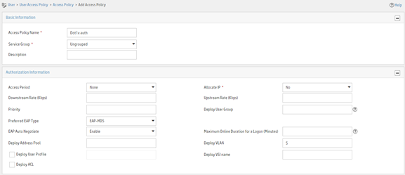
Adding an access policy
1. Click the User tab.
2. From the navigation pane, select User Access Policy > Access Policy.
3. Click Add.
4. On the page that opens, configure access policy parameters.
a. Enter access policy name Dot1x auth.
b. Enter 5 in the Deploy VLAN field.
c. Configure other parameters as needed.
d. Click OK.
Figure 21 Adding an access policy
Adding an access service
1. Click the User tab.
2. From the navigation pane, select User Access Policy > Access Service.
3. Click Add.
4. On the page that opens, configure access service parameters.
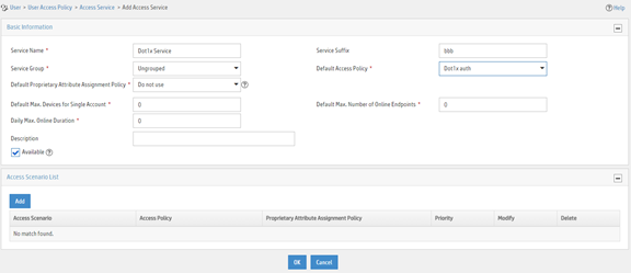
a. Enter service name Dot1x Service and set the service suffix to bbb. The service suffix is the authentication domain for the 802.1X user.
|
|
IMPORTANT: With the service suffix configured, you must configure the device to send usernames that include the domain name to the RADIUS server. |
b. Select Dot1x auth from the Default Access Policy list.
c. Configure other parameters as needed.
d. Click OK.
Figure 22 Adding an access service

Adding an access user
1. Click the User tab.
2. From the navigation pane, select Access User > Access User.
3. Click Add.
4. On the page that opens, configure access user parameters.
a. Select the user or add a user named test.
b. Enter account name dot1x and password 123456TESTplat&!.
c. Select Dot1x Service in the Access Service area.
d. Configure other parameters as needed.
e. Click OK.
Figure 23 Adding an access user
Configuring the device
1. Create VLANs, and assign ports to the VLANs.
|
|
NOTE: By default, VLAN 1 exists and all ports belong to the VLAN. You do not need to create the VLAN or assign GigabitEthernet 1/0/2 to the VLAN. |
<Device> system-view
[Device] vlan 10
[Device-vlan10] port gigabitethernet 1/0/1
[Device-vlan10] quit
[Device] vlan 2
[Device-vlan2] port gigabitethernet 1/0/4
[Device-vlan2] quit
[Device] vlan 5
[Device-vlan5] port gigabitethernet 1/0/3
[Device-vlan5] quit
2. Configure a QoS policy to filter VLAN 10 traffic destined for the Internet (5.1.1.1):
# Configure advanced ACL 3000 to match the packets destined for 5.1.1.1.
[Device] acl advanced 3000
[Device-acl-ipv4-adv-3000] rule permit ip destination 5.1.1.1 0.0.0.255
[Device-acl-ipv4-adv-3000] quit
# Create a traffic class named classifier_1 and use ACL 3000 as the match criterion.
[Device] traffic classifier classifier_1
[Device-classifier-classifier_1] if-match acl 3000
[Device-classifier-classifier_1] quit
# Create a traffic behavior named behavior_1 and add a deny filter action to drop packets.
[Device] traffic behavior behavior_1
[Device-behavior-behavior_1] filter deny
[Device-behavior-behavior_1] quit
# Create a QoS policy named policy_1. Associate traffic class classifier_1 with traffic behavior behavior_1 in the QoS policy.
[Device] qos policy policy_1
[Device-qospolicy-policy_1] classifier classifier_1 behavior behavior_1
[Device-qospolicy-policy_1] quit
# Apply QoS policy policy_1 to the outbound direction of VLAN 10.
[Device] qos vlan-policy policy_1 vlan 10 outbound
3. Configure a RADIUS scheme:
# Create a RADIUS scheme named 2000 and enter RADIUS scheme view.
[Device] radius scheme 2000
# Specify the server at 10.1.1.1 as the primary authentication server, and set the authentication port to 1812.
[Device-radius-2000] primary authentication 10.1.1.1 1812
# Specify the server at 10.1.1.1 as the primary accounting server, and set the accounting port to 1813.
[Device-radius-2000] primary accounting 10.1.1.1 1813
# Set the shared key to expert in plaintext form for secure communication between the authentication server and the device.
[Device-radius-2000] key authentication simple expert
# Set the shared key to expert in plaintext form for secure communication between the accounting server and the device.
[Device-radius-2000] key accounting simple expert
# Include the ISP domain name in the usernames sent to the RADIUS server. This step is optional. By default, the ISP domain name is included in the usernames sent to a RADIUS server.
[Device-radius-2000] user-name-format with-domain
[Device-radius-2000] quit
4. Configure an ISP domain:
# Create ISP domain bbb and enter ISP domain view.
[Device] domain bbb
# Apply RADIUS scheme 2000 to the ISP domain for LAN user authentication, authorization, and accounting.
[Device-isp-bbb] authentication lan-access radius-scheme 2000
[Device-isp-bbb] authorization lan-access radius-scheme 2000
[Device-isp-bbb] accounting lan-access radius-scheme 2000
[Device-isp-bbb] quit
5. Configure 802.1X:
# Enable 802.1X on interface GigabitEthernet 1/0/2.
[Device] interface gigabitethernet 1/0/2
[Device-GigabitEthernet1/0/2] dot1x
# Enable 802.1X port-based access control on the interface.
[Device-GigabitEthernet1/0/2] dot1x port-method portbased
# Set the port authorization mode to auto. This step is optional. By default, the port uses the auto mode.
[Device-GigabitEthernet1/0/2] dot1x port-control auto
# Specify VLAN 10 as the 802.1X guest VLAN on interface GigabitEthernet 1/0/2.
[Device-GigabitEthernet1/0/2] dot1x guest-vlan 10
[Device-GigabitEthernet1/0/2] quit
# Enable 802.1X globally.
[Device] dot1x
Configuring the 802.1X client
# Configure the 802.1X client. Make sure the 802.1X client can update its IP address after the access port is assigned to the guest VLAN or an authorization VLAN. (Details not shown.)
Verifying the configuration
# Verify the 802.1X guest VLAN configuration on GigabitEthernet 1/0/2.
[Device] display dot1x interface gigabitethernet 1/0/2
# Verify that GigabitEthernet 1/0/2 is assigned to VLAN 10 before any user passes authentication on the port.
[Device] display vlan 10
# After a user passes authentication, display information on GigabitEthernet 1/0/2. Verify that GigabitEthernet 1/0/2 is assigned to VLAN 5.
[Device] display interface gigabitethernet 1/0/2
Configuration files
#
vlan 2
#
vlan 5
#
vlan 10
#
acl advanced 3000
rule 0 permit ip destination 5.1.1.0 0.0.0.255
#
traffic classifier classifier_1 operator and
if-match acl 3000
#
traffic behavior behavior_1
filter deny
#
qos policy policy_1
classifier classifier_1 behavior behavior_1
#
qos vlan-policy policy_1 vlan 10 outbound
#
radius scheme 2000
primary authentication 10.1.1.1
primary accounting 10.1.1.1
key authentication cipher $c$3$LAV0oGNaM9Z/CuVcWONBH4xezu48Agh5aQ==
key accounting cipher $c$3$LAV0oGNaM9Z/CuVcWONBH4xezu48Agh5aQ==
#
domain bbb
authentication lan-access radius-scheme 2000
authorization lan-access radius-scheme 2000
accounting lan-access radius-scheme 2000
#
interface GigabitEthernet1/0/1
port access vlan 10
#
interface GigabitEthernet1/0/2
dot1x
dot1x port-method portbased
dot1x guest-vlan 10
#
interface GigabitEthernet1/0/3
port access vlan 5
#
interface GigabitEthernet1/0/4
port access vlan 2
#
dot1x
#
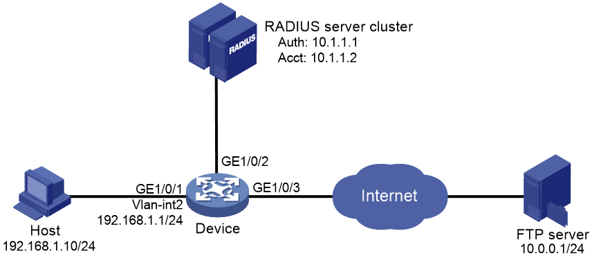
Example: Configuring 802.1X with ACL assignment
Network configuration
As shown in Figure 24, the user on the host that connects to GigabitEthernet 1/0/1 must pass 802.1X authentication to access the Internet.
Perform 802.1X authentication on GigabitEthernet 1/0/1. Use the RADIUS server at 10.1.1.1 as the authentication and authorization server, and the RADIUS server at 10.1.1.2 as the accounting server.
Configure ACL assignment on GigabitEthernet 1/0/1 to deny access of 802.1X users to the FTP server from 8:00 to 18:00 on weekdays.
Analysis
· For the device to use the RADIUS server for user authentication, perform the following tasks on the RADIUS server:
a. Add the device as an access device to the RADIUS server.
b. Add an access policy.
c. Add an access service and specify the access policy in the access service.
d. Add an access user and specify the access service for the access user.
· For the device to perform RADIUS-based authentication and authorization for the 802.1X user, configure AAA settings on the device, including ISP domain settings and RADIUS scheme settings.
· To assign an ACL to the user after the user passes authentication and use the ACL to restrict the user's access behaviors, perform the following tasks:
¡ Specify the ACL in the user account on the RADIUS server.
¡ Create the ACL and configure its rules on the device.
Applicable hardware and software versions
The following matrix shows the hardware and software versions to which this configuration example is applicable:
|
Hardware |
Software versions |
|
S6812 switch series S6813 switch series |
Release 66xx |
|
S6550XE-HI switch series |
Release 6008 and later |
|
S6525XE-HI switch series |
Release 6008 and later |
|
S5850 switch series |
Release 8005 and later |
|
S5570S-EI switch series |
Release 11xx |
|
S5560X-EI switch series |
Release 63xx, Release 65xx, Release 66xx |
|
S5560X-HI switch series |
Release 63xx, Release 65xx, Release 66xx |
|
S5500V2-EI switch series |
Release 63xx, Release 65xx, Release 66xx |
|
MS4520V2-30F switch |
Release 63xx, Release 65xx, Release 66xx |
|
MS4520V2-30C switch MS4520V2-54C switch |
Release 65xx |
|
MS4520V2-28S switch MS4520V2-24TP switch |
Release 63xx |
|
S6520X-HI switch series S6520X-EI switch series |
Release 63xx, Release 65xx, Release 66xx |
|
S6520X-SI switch series S6520-SI switch series |
Release 63xx, Release 65xx, Release 66xx |
|
S5000-EI switch series |
Release 63xx, Release 65xx, Release 66xx |
|
MS4600 switch series |
Release 63xx, Release 65xx, Release 66xx |
|
ES5500 switch series |
Release 63xx, Release 65xx, Release 66xx |
|
S5560S-EI switch series S5560S-SI switch series |
Release 63xx |
|
S5500V3-24P-SI switch S5500V3-48P-SI switch |
Release 63xx |
|
S5500V3-SI switch series (except the S5500V3-24P-SI and S5500V3-48P-SI switches) |
Release 11xx |
|
S5170-EI switch series |
Release 11xx |
|
S5130S-HI switch series S5130S-EI switch series S5130S-SI switch series S5130S-LI switch series |
Release 63xx |
|
S5120V2-SI switch series S5120V2-LI switch series |
Release 63xx |
|
S5120V3-EI switch series |
Release 11xx |
|
S5120V3-36F-SI switch S5120V3-28P-HPWR-SI switch S5120V3-54P-PWR-SI switch |
Release 11xx |
|
S5120V3-SI switch series (except the S5120V3-36F-SI, S5120V3-28P-HPWR-SI, and S5120V3-54P-PWR-SI switches) |
Release 63xx |
|
S5120V3-LI switch series |
Release 63xx |
|
S3600V3-EI switch series |
Release 11xx |
|
S3600V3-SI switch series |
Release 11xx |
|
S3100V3-EI switch series S3100V3-SI switch series |
Release 63xx |
|
S5110V2 switch series |
Release 63xx |
|
S5110V2-SI switch series |
Release 63xx |
|
S5000V3-EI switch series S5000V5-EI switch series |
Release 63xx |
|
S5000E-X switch series S5000X-EI switch series |
Release 63xx |
|
E128C switch E152C switch E500C switch series E500D switch series |
Release 63xx |
|
MS4320V2 switch series MS4320V3 switch series MS4300V2 switch series MS4320 switch series MS4200 switch series |
Release 63xx |
|
WS5850-WiNet switch series |
Release 63xx |
|
WS5820-WiNet switch series WS5810-WiNet switch series |
Release 63xx |
|
WAS6000 switch series |
Release 63xx |
|
IE4300-12P-AC switch IE4300-12P-PWR switch IE4300-M switch series IE4320 switch series |
Release 63xx |
Restrictions and guidelines
· If the server assigns both an authorization ACL and microsegment to an 802.1X authentication user on a microsegmented network, only the authorization microsegment takes effect.
· In this example, the RADIUS server assigns only an ACL number to the 802.1X user. You must manually create the ACL and configure its rules on the device.
· To change the access permissions of the 802.1X user, you can use one of the following methods:
¡ Modify ACL rules in the authorization ACL on the device.
¡ Assign another ACL to the user as the authorization ACL from the RADIUS server.
Procedures
For information about the ISP domain and RADIUS commands used on the device in this example, see AAA commands in Security Command Reference.
Configuring the RADIUS server
This example uses IMC PLAT 7.3 (E0506), IMC EIA 7.3 (E0503), and IMC EIP 7.3 (E0503) to describe the procedure.
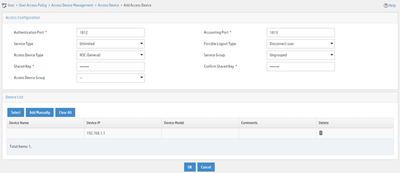
Adding the device to the IMC Platform as an access device
1. Log in to IMC.
2. Click the User tab.
3. From the navigation pane, select User Access Policy > Access Device Management > Access Device.
4. Click Add.
5. On the page that opens, configure access device parameters.
a. Set the ports for authentication and accounting to 1812 and 1813, respectively.
b. Select H3C (General) from the Access Device Type list.
c. Set the shared key to expert for secure authentication and accounting communication.
d. Select an access device from the device list or manually add an access device. In this example, the device IP address is 192.168.1.1.
e. Use the default values for other parameters and click OK.
The IP address of the access device specified on the RADIUS server must be the same as the source IP address of the RADIUS packets sent from the device. On the device, the source IP address is chosen in the following order:
a. IP address specified by using the nas-ip command.
b. IP address specified by using the radius nas-ip command.
c. IP address of the outbound interface (the default).
In this example, the device uses the IP address of the outbound interface as the source IP address of RADIUS packets.
Figure 25 Adding an access device
Adding an access policy
1. Click the User tab.
2. From the navigation pane, select User Access Policy > Access Policy.
3. Click Add.
4. On the page that opens, configure access policy parameters.
a. Enter access policy name Dot1x auth.
b. In the Authorization Information area, select Deploy ACL and manually enter ACL number 3000.
c. Configure other parameters as needed.
d. Click OK.
Figure 26 Adding an access policy
Adding an access service
1. Click the User tab.
2. From the navigation pane, select User Access Policy > Access Service.
3. Click Add.
4. On the page that opens, configure access service parameters.
a. Enter service name Dot1x Service and set the service suffix to bbb. The service suffix is the authentication domain for the 802.1X user.
|
|
IMPORTANT: With the service suffix configured, you must configure the device to send usernames that include the domain name to the RADIUS server. |
b. Select Dot1x auth from the Default Access Policy list.
c. Configure other parameters as needed.
d. Click OK.
Figure 27 Adding an access service
Adding an access user
1. Click the User tab.
2. From the navigation pane, select Access User > Access User.
3. Click Add.
4. On the page that opens, configure user parameters.
a. Select the user or add a user named test.
b. Enter account name dot1x and password 123456TESTplat&!.
c. Select Dot1x Service in the Access Service area.
d. Configure other parameters as needed.
e. Click OK.
Figure 28 Adding an access user

Configuring the device
1. Configure IP addresses for interfaces. (Details not shown.)
2. Configure a RADIUS scheme.
|
|
IMPORTANT: With the service suffix configured on IMC, you must configure the device to send usernames that include the domain name to the RADIUS server. By default, the device includes the domain name in the usernames sent to a RADIUS server. |
<Device> system-view
[Device] radius scheme 2000
[Device-radius-2000] primary authentication 10.1.1.1 1812
[Device-radius-2000] primary accounting 10.1.1.2 1813
[Device-radius-2000] key authentication simple expert
[Device-radius-2000] key accounting simple expert
[Device-radius-2000] user-name-format with-domain
[Device-radius-2000] quit
3. Configure an ISP domain and specify the authentication, authorization, and accounting methods for users in the domain.
[Device] domain bbb
[Device-isp-bbb] authentication lan-access radius-scheme 2000
[Device-isp-bbb] authorization lan-access radius-scheme 2000
[Device-isp-bbb] accounting lan-access radius-scheme 2000
[Device-isp-bbb] quit
4. Configure a time range named ftp that contains a time span from 8:00 to 18:00 on weekdays.
[Device] time-range ftp 8:00 to 18:00 working-day
5. Configure ACL 3000 to deny packets destined for the FTP server at 10.0.0.1 during the specified time span.
[Device] acl advanced 3000
[Device-acl-ipv4-adv-3000] rule 0 deny ip destination 10.0.0.1 0 time-range ftp
[Device-acl-ipv4-adv-3000] quit
6. Configure 802.1X:
# Enable 802.1X on interface GigabitEthernet 1/0/1.
[Device] interface gigabitethernet 1/0/1
[Device-GigabitEthernet1/0/1] dot1x
# Enable 802.1X globally.
[Device] dot1x
Configuring the 802.1X client
# Configure the 802.1X client. Make sure the client is able to update its IP address after the access port is assigned to the 802.1X guest VLAN or an authorization VLAN. (Details not shown.)
Verifying the configuration
# Use the user account to pass authentication. (Details not shown.)
# Verify that the user cannot ping the FTP server at any time from 8:00 to 18:00 on any weekday.
C:\>ping 10.0.0.1
Pinging 10.0.0.1 with 32 bytes of data:
Request timed out.
Request timed out.
Request timed out.
Request timed out.
Ping statistics for 10.0.0.1:
Packets: Sent = 4, Received = 0, Lost = 4 (100% loss),
The output shows that ACL 3000 is active on the user, and the user cannot access the FTP server.
Configuration files
#
time-range ftp 8:00 to 18:00 working-day
#
radius scheme 2000
primary authentication 10.1.1.1
primary accounting 10.1.1.2
key authentication cipher $c$3$LAV0oGNaM9Z/CuVcWONBH4xezu48Agh5aQ==
key accounting cipher $c$3 $LAV0oGNaM9Z/CuVcWONBH4xezu48Agh5aQ==
#
domain bbb
authentication lan-access radius-scheme 2000
authorization lan-access radius-scheme 2000
accounting lan-access radius-scheme 2000
#
acl advanced 3000
rule 0 deny ip destination 10.0.0.1 0 time-range ftp
#
interface GigabitEthernet1/0/1
port link-mode bridge
dot1x
#
dot1x
#
