- Table of Contents
-
- H3C SecPath M9000 Multi Service Security Gateway Configuration Examples(V7)(E9X71)-6W700
- 00-Preface
- 01-About the configuration examples
- 02-Web Login Configuration Examples
- 03-Internet Access Through a Static IP Address Configuration Examples
- 04-Internet access through PPPoE configuration examples
- 05-License Configuration Examples
- 06-Signature Library Upgrade Configuration Examples
- 07-Software Upgrade Examples
- 08-Routing deployment configuration examples
- 09-Transparent deployment configuration examples
- 10-Static routing configuration examples
- 11-RIP configuration examples
- 12-OSPF configuration examples
- 13-BGP configuration examples
- 14-Policy-based routing configuration examples
- 15-Security Policy Configuration Examples
- 16-APR-Based Security Policy Configuration Examples
- 17-Object Group Configuration Examples
- 18-User identification configuration examples
- 19-Attack defense configuration examples
- 20-Request Limit Configuration Examples
- 21-IPS Configuration Examples
- 22-URL Filtering Configuration Examples
- 23-Anti-Virus Configuration Examples
- 24-File Filtering Configuration Examples
- 25-Data Filtering Configuration Examples
- 26-WAF Configuration Examples
- 27-IP Reputation Configuration Examples
- 28-APT Defense Configuration Examples
- 29-NetShare Control Configuration Examples
- 30-Bandwidth Management Configuration Examples
- 31-IPsec configuration examples
- 32-SSL VPN IP access configuration examples
- 32-SSL VPN TCP access configuration examples
- 32-SSL VPN Web access configuration examples
- 33-L2TP Configuration Examples
- 34-NAT configuration examples
- 35-NPTv6 Configuration Examples
- 36-Policy-based NAT configuration examples
- 37-NAT hairpin configuration examples
- 38-NAT Flow Logging Configuration Examples
- 39-Inbound Link Load Balancing Configuration Examples
- 40-Outbound Link Load Balancing Configuration Examples
- 41-Server Load Balancing Configuration Examples
- 42-Transparent DNS Proxy Configuration Examples
- 43-Hot Backup Configuration Examples
- 44-Context Configuration Examples
- 45-DNS configuration examples
- 46-Server Connection Detection Configuration Examples
- 47-Connection Limit Configuration Examples
- 48-Public key management configuration examples
- 49-SSL Decryption Configuration Examples
- 50-MAC Address Learning Through a Layer 3 Device Configuration Examples
- 51-4G Configuration Examples
- 52-WLAN Configuration Examples
- Related Documents
-
| Title | Size | Download |
|---|---|---|
| 48-Public key management configuration examples | 219.08 KB |
Public key management configuration examples
Contents
· Example: Entering a peer host public key
· Example: Importing a peer host public key from a public key file
The following information provides configuration examples for public key management.
This document is not restricted to specific software or hardware versions. Procedures and information in the examples might be slightly different depending on the software or hardware version of the device.
The configuration examples were created and verified in a lab environment, and all the devices were started with the factory default configuration. When you are working on a live network, make sure you understand the potential impact of every command on your network.
The following information is provided based on the assumption that you have basic knowledge of public key management.
When you manually enter the peer host public key, make sure the entered key is in the correct format. To obtain the peer host public key in the correct format, display the public key on the peer device and record the key. The format of the public key displayed in any other way might be incorrect. If the key is not in the correct format, the system discards the key and displays an error message.
As a best practice, import rather than enter the peer host public key if you are not sure whether the device supports the format of the recorded peer host public key.
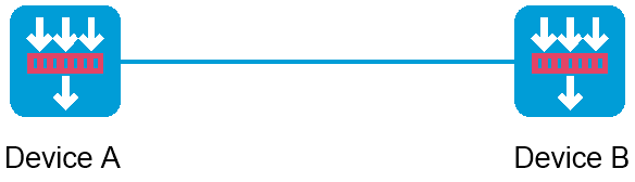
Network configuration
As shown in Figure 1, to prevent illegal access from Device A to Device B, Device B authenticates Device A through a digital signature. Before configuring authentication parameters on Device B, use the following procedure to configure the public key of Device A on Device B:
· Create RSA key pairs on Device A and display the public keys of the RSA key pairs.
· Manually specify the RSA host public key of Device A on Device B.

Software versions used
This configuration example was created and verified on E8371 of the F5000-AI160 device.
This configuration example was created and verified on E9671 of the M9000-X06 device.
Procedures
Configuring Device A
# On the top navigation bar, click Objects.
# From the navigation pane, select Public Key Management > Local Key Pairs.
# Click Create. The Create Local Key Pair page opens.
# Create an RSA local key pair as follows:
· Enter key pair name devicea-rsa.
· Select the RSA algorithm.
· Enter key length 1800.
# Click OK.
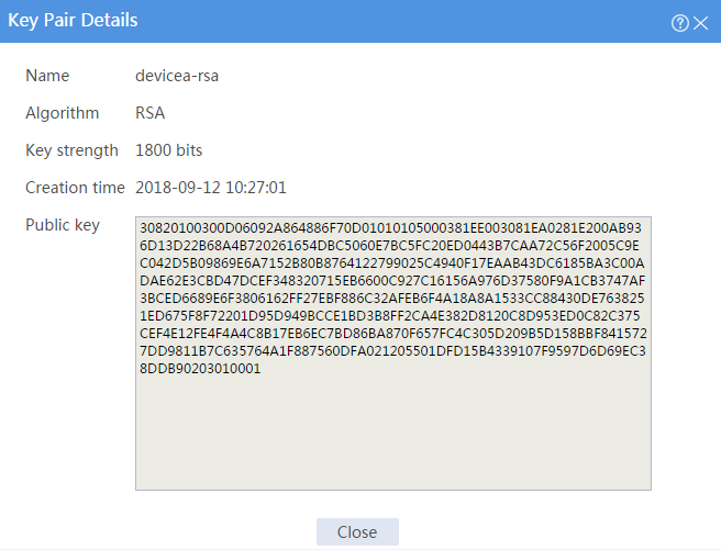
# Click key pair name devicea-rsa to open the Key Pair Details page.
# Record the data displayed in the Public key field.
Figure 2 Creating a local key pair
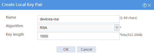
Figure 3 Key details
Configuring Device B
# On the top navigation bar, click Objects.
# From the navigation pane, select Public Key Management > Local Key Pairs.
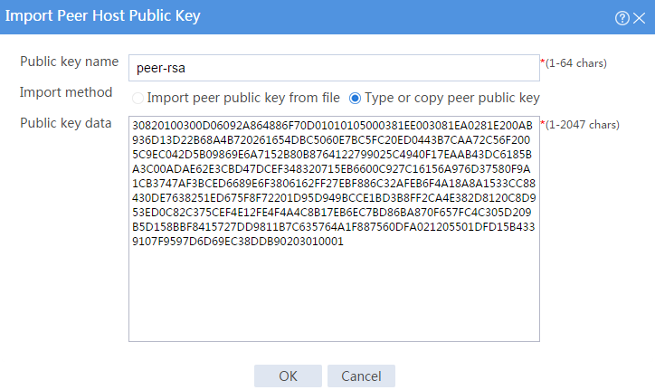
# Click Import. The Import Peer Host Public Key page opens.
# Configure the peer host public key as follows:
· Enter public key name peer-rsa.
· Select the Type or copy peer public key import method.
· In the Public key data field, type the public key data of Device A, or copy and then paste the public key data of Device A.
# Click OK.
Figure 4 Entering the peer host public key
Verifying the configuration
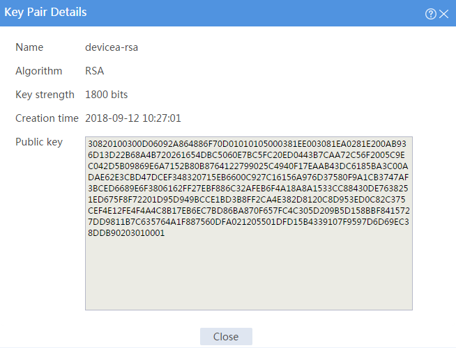
1. Display information about the local public key on Device A.
# On the top navigation bar, click Objects.
# From the navigation pane, Public Key Management > Local Key Pairs.
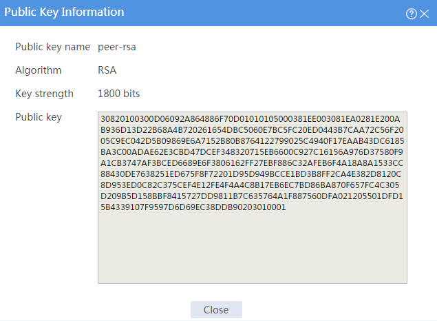
# Click the Details icon for key pair devicea-rsa to open the Key Pair Details page. The Public key field displays the content of the public key.
Figure 5 Local host public key information
2. Display information about the peer public key configured on Device B.
# On the top navigation bar, click Objects.
# From the navigation pane, Public Key Management > Peer Public Keys.
# Click the Details icon for public key peer-rsa.
Figure 6 Manually configured peer host public key
Network configuration
As shown in Figure 7, to prevent illegal access from Device A to Device B, Device B authenticates Device A through a digital signature. Before configuring authentication parameters on Device B, use the following procedure to configure the public key of Device A on Device B:
· Create RSA key pairs on Device A and export the RSA host public key to a file.
· Import the RSA host public key of Device A from the public key file to Device B.
Software versions used
This configuration example was created and verified on E8371 of the F5000-AI160 device.
This configuration example was created and verified on E9671 of the M9000-X06 device.
Procedures
Configuring Device A
# On the top navigation bar, click Objects.
# From the navigation pane, select Public Key Management > Local Key Pairs.
# Click Create. The Create Local Key Pair page opens.
Figure 8 Creating a local key pair

# Create an RSA local key pair as follows:
· Enter key pair name devicea-rsa.
· Select the RSA algorithm.
· Enter key length 1800.
# Click OK.
# Select key pair devicea-rsa, and then click Export. The Export Local Key Pair page opens.
Figure 9 Exporting a local host public key
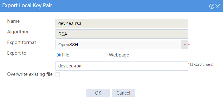
# Select the OpenSSH export format, export the host public key to a file named devicea-rsa, and then click OK.
# After the key is exported to file devicea-rsa, transfer the file to the peer device (Device B). (Details not shown.)
Configuring Device B
# On the top navigation bar, click Objects.
# From the navigation pane, select Public Key Management > Local Key Pairs.
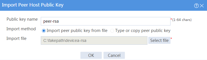
# Click Import. The Import Peer Host Public Key page opens.
# Configure the peer host public key as follows:
· Enter public key name peer-rsa.
· Select the Import peer public key from file import method.
· Select the path of public key file devicea-rsa.
# Click OK.
Figure 10 Importing the peer host public key from a public key file
Verifying the configuration
1. Display information about the local public key on Device A.
# On the top navigation bar, click Objects.
# From the navigation pane, select Public Key Management > Local Key Pairs.
# Click the Details icon for key pair devicea-rsa to open the Key Pair Details page. The Public key field displays the content of the public key.
Figure 11 Local host public key information

2. Display information about the peer public key configured on Device B.
# On the top navigation bar, click Objects.
# From the navigation pane, select Public Key Management > Peer Public Keys.
# Click the Details icon for public key peer-rsa.
Figure 12 Peer host public key imported from a public key file

