- Table of Contents
-
- H3C SecPath M9000 Multi Service Security Gateway Configuration Examples(V7)(E9X71)-6W700
- 00-Preface
- 01-About the configuration examples
- 02-Web Login Configuration Examples
- 03-Internet Access Through a Static IP Address Configuration Examples
- 04-Internet access through PPPoE configuration examples
- 05-License Configuration Examples
- 06-Signature Library Upgrade Configuration Examples
- 07-Software Upgrade Examples
- 08-Routing deployment configuration examples
- 09-Transparent deployment configuration examples
- 10-Static routing configuration examples
- 11-RIP configuration examples
- 12-OSPF configuration examples
- 13-BGP configuration examples
- 14-Policy-based routing configuration examples
- 15-Security Policy Configuration Examples
- 16-APR-Based Security Policy Configuration Examples
- 17-Object Group Configuration Examples
- 18-User identification configuration examples
- 19-Attack defense configuration examples
- 20-Request Limit Configuration Examples
- 21-IPS Configuration Examples
- 22-URL Filtering Configuration Examples
- 23-Anti-Virus Configuration Examples
- 24-File Filtering Configuration Examples
- 25-Data Filtering Configuration Examples
- 26-WAF Configuration Examples
- 27-IP Reputation Configuration Examples
- 28-APT Defense Configuration Examples
- 29-NetShare Control Configuration Examples
- 30-Bandwidth Management Configuration Examples
- 31-IPsec configuration examples
- 32-SSL VPN IP access configuration examples
- 32-SSL VPN TCP access configuration examples
- 32-SSL VPN Web access configuration examples
- 33-L2TP Configuration Examples
- 34-NAT configuration examples
- 35-NPTv6 Configuration Examples
- 36-Policy-based NAT configuration examples
- 37-NAT hairpin configuration examples
- 38-NAT Flow Logging Configuration Examples
- 39-Inbound Link Load Balancing Configuration Examples
- 40-Outbound Link Load Balancing Configuration Examples
- 41-Server Load Balancing Configuration Examples
- 42-Transparent DNS Proxy Configuration Examples
- 43-Hot Backup Configuration Examples
- 44-Context Configuration Examples
- 45-DNS configuration examples
- 46-Server Connection Detection Configuration Examples
- 47-Connection Limit Configuration Examples
- 48-Public key management configuration examples
- 49-SSL Decryption Configuration Examples
- 50-MAC Address Learning Through a Layer 3 Device Configuration Examples
- 51-4G Configuration Examples
- 52-WLAN Configuration Examples
- Related Documents
-
| Title | Size | Download |
|---|---|---|
| 10-Static routing configuration examples | 72.66 KB |
Static routing configuration examples
Contents
· Example: Configuring static routes
The following information provides static routing configuration examples.
Static routes are manually configured. If a network's topology is simple, you only need to configure static routes for the network to work correctly.
Static routes cannot adapt to network topology changes. If a fault or a topological change occurs in the network, the network administrator must modify the static routes manually.
This document is not restricted to specific software or hardware versions. Procedures and information in the examples might be slightly different depending on the software or hardware version of the device.
The configuration examples were created and verified in a lab environment, and all the devices were started with the factory default configuration. When you are working on a live network, make sure you understand the potential impact of every command on your network.
The following information is provided based on the assumption that you have basic knowledge of the static routing feature.
When you configure a static route, make sure the network of its next hop is reachable. In addition, make sure the next hop device has a minimum of one route to reach the local device.
Network configuration
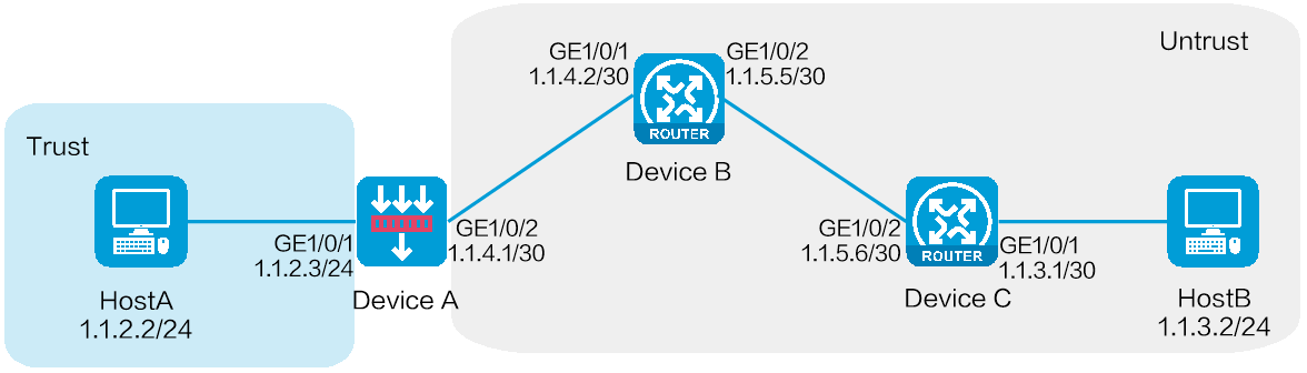
As shown in Figure 1, configure static routes on Device A, Device B, and Device C for interconnections between Host A and Host B.
Figure 1 Network diagram
Software versions used
This configuration example was created and verified on E8371 of the F5000-AI160 device.
This configuration example was created and verified on E9671 of the M9000-X06 device.
Procedure
Configuring Device A
1. Assign IP addresses to interfaces and add the interfaces to security zones:
# On the top navigation bar, click Network.
# From the navigation pane, select Interface Configuration > Interfaces.
# Click the Edit icon for GE 1/0/2.
# In the dialog box that opens, configure the interface:
a. Select the Untrust security zone.
b. Click the IPv4 Address tab, and then enter the IP address and mask length of the interface. In this example, enter 1.1.4.1/30.
c. Click OK.
# Add GE 1/0/1 to the Trust security zone and set its IP address to 1.1.2.3/24 in the same way you configure GE 1/0/2.
2. Configure security policies:
# On the top navigation bar, click Policies.
# From the navigation pane, select Security Policies > Security Policies.
# Click Create.
# In the dialog box that opens, configure security policy test-a:
¡ Enter security policy name test-a.
¡ Select source zone Trust.
¡ Select destination zone Untrust.
¡ Set the type to IPv4.
¡ Set the action to Permit.
¡ Set the source IPv4 address to 1.1.2.2/24.
¡ Set the destination IPv4 address to 1.1.3.2/24.
# Click OK.
# Click Create to create another security policy.
# In the dialog box that opens, configure security policy test-b:
¡ Enter security policy name test-b.
¡ Select source zone Untrust.
¡ Select destination zone Trust.
¡ Set the type to IPv4.
¡ Set the action to Permit.
¡ Set the source IPv4 address to 1.1.3.2/24.
¡ Set the destination IPv4 address to 1.1.2.2/24.
# Click OK.
3. Configure a static route:
# On the top navigation bar, click Network.
# From the navigation pane, select Routing > Static Routing.
# On the IPv4 Static Routing tab, click Create.
# In the dialog box that opens, configure an IPv4 static route, as shown in Figure 2.
Figure 2 Creating an IPv4 static route
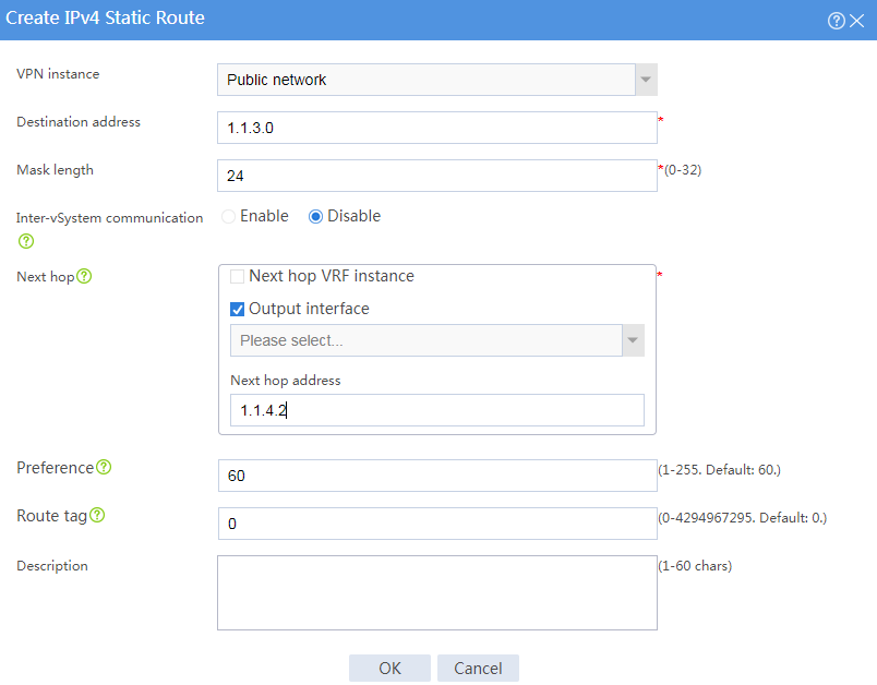
# Click OK.
Configuring Device B
# Configure two static routes to reach networks 1.1.2.0/24 (Device A) and 1.1.3.0/24 (Device C), respectively. The configuration method is the same as that you configure the static route on Device A. (Details not shown.)
Configuring Device C
# Configure two static routes to reach networks 1.1.2.0/24 (Device A) and 1.1.4.0/30 (Device B), respectively. The configuration method is the same as that you configure the static route on Device A. (Details not shown.)
Verifying the configuration
# Verify that Host A can ping Host B.
C:\Users\abc>ping 1.1.3.2
Pinging 1.1.3.2 with 32 bytes of data:
Reply from 1.1.3.2: bytes=32 time=1ms TTL=255
Reply from 1.1.3.2: bytes=32 time=1ms TTL=255
Reply from 1.1.3.2: bytes=32 time=1ms TTL=255
Reply from 1.1.3.2: bytes=32 time=1ms TTL=255
Ping statistics for 1.1.3.2:
Packets: Sent = 4, Received = 4, Lost = 0 (0% loss),
Approximate round trip times in milli-seconds:
Minimum = 1ms, Maximum = 1ms, Average = 1ms
The output shows that Host B can be pinged from Host A.
