- Table of Contents
-
- H3C SecPath M9000 Multi Service Security Gateway Configuration Examples(V7)(E9X71)-6W700
- 00-Preface
- 01-About the configuration examples
- 02-Web Login Configuration Examples
- 03-Internet Access Through a Static IP Address Configuration Examples
- 04-Internet access through PPPoE configuration examples
- 05-License Configuration Examples
- 06-Signature Library Upgrade Configuration Examples
- 07-Software Upgrade Examples
- 08-Routing deployment configuration examples
- 09-Transparent deployment configuration examples
- 10-Static routing configuration examples
- 11-RIP configuration examples
- 12-OSPF configuration examples
- 13-BGP configuration examples
- 14-Policy-based routing configuration examples
- 15-Security Policy Configuration Examples
- 16-APR-Based Security Policy Configuration Examples
- 17-Object Group Configuration Examples
- 18-User identification configuration examples
- 19-Attack defense configuration examples
- 20-Request Limit Configuration Examples
- 21-IPS Configuration Examples
- 22-URL Filtering Configuration Examples
- 23-Anti-Virus Configuration Examples
- 24-File Filtering Configuration Examples
- 25-Data Filtering Configuration Examples
- 26-WAF Configuration Examples
- 27-IP Reputation Configuration Examples
- 28-APT Defense Configuration Examples
- 29-NetShare Control Configuration Examples
- 30-Bandwidth Management Configuration Examples
- 31-IPsec configuration examples
- 32-SSL VPN IP access configuration examples
- 32-SSL VPN TCP access configuration examples
- 32-SSL VPN Web access configuration examples
- 33-L2TP Configuration Examples
- 34-NAT configuration examples
- 35-NPTv6 Configuration Examples
- 36-Policy-based NAT configuration examples
- 37-NAT hairpin configuration examples
- 38-NAT Flow Logging Configuration Examples
- 39-Inbound Link Load Balancing Configuration Examples
- 40-Outbound Link Load Balancing Configuration Examples
- 41-Server Load Balancing Configuration Examples
- 42-Transparent DNS Proxy Configuration Examples
- 43-Hot Backup Configuration Examples
- 44-Context Configuration Examples
- 45-DNS configuration examples
- 46-Server Connection Detection Configuration Examples
- 47-Connection Limit Configuration Examples
- 48-Public key management configuration examples
- 49-SSL Decryption Configuration Examples
- 50-MAC Address Learning Through a Layer 3 Device Configuration Examples
- 51-4G Configuration Examples
- 52-WLAN Configuration Examples
- Related Documents
-
| Title | Size | Download |
|---|---|---|
| 19-Attack defense configuration examples | 236.92 KB |
Attack defense configuration examples
Contents
· Example: Configuring scanning attack defense
· Example: Configuring flood attack defense
The following information describes attack defense configuration examples.
The following attack defense features are supported:
Scanning attack defense
Scanning attack detection inspects the incoming packet rate of connections to the target system. Apply a scanning attack defense policy to the security zone that is connected to the external network.
Global flood attack defense
Apply a flood attack defense policy to the security zone that is connected to the external network to protect internal servers. Flood attack detection monitors the rate at which connections are initiated to the internal servers.
IP-specific flood attack defense
You can configure flood attack detection and defense for specific IP addresses. For non-specific IP addresses, the device uses the global flood attack defense settings.
Well-known single-packet attack defense
Single-packet attack detection inspects incoming packets based on the packet signature. Apply the single-packet attack defense policy to the security zone that is connected to the external network.
User-defined single-packet attack defense
The device supports detecting attack packets with user-defined signatures.
Exemption list
The attack defense policy uses an ACL to identify exempted packets. The policy does not check the packets permitted by the ACL.
This document is not restricted to specific software or hardware versions. Procedures and information in the examples might be slightly different depending on the software or hardware version of the device.
The configuration examples were created and verified in a lab environment, and all the devices were started with the factory default configuration. When you are working on a live network, make sure you understand the potential impact of every command on your network.
The following information is provided based on the assumption that you have basic knowledge of attack detection and defense.
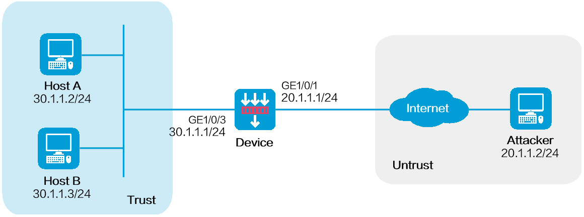
Network configuration
As shown in Figure 1, configure middle-level scanning attack detection and defense on the Untrust security zone where GigabitEthernet 1/0/1 resides to protect internal hosts from scanning attacks. The defense actions are logging and dropping attack packets.
Software versions used
This configuration example was created and verified on E8371 of the F5000-AI160 device and E9671 of the M9000-X06 device.
Procedure
1. Assign IP addresses to interfaces and add the interfaces to security zones.
# On the top navigation bar, click Network.
# From the navigation pane, select Interface Configuration > Interfaces.
# Click the Edit icon for GE 1/0/1.
# In the dialog box that opens, configure the interface:
a. Select the Untrust security zone.
b. On the IPv4 Address tab, enter the IP address and mask of the interface. In this example, enter 20.1.1.1/24.
c. Click OK.
# Add GE 1/0/3 to the Trust security zone and set its IP address to 30.1.1.1/24 in the same way you configure GE 1/0/1.
2. Create a security policy from zone Untrust to zone Trust.
# On the top navigation bar, click Policies.
# From the navigation pane, select Security Policies > Security Policies.
# Click Create.
# In the dialog box that opens, configure a security policy:
¡ Enter policy name Secpolicy.
¡ Select source zone Untrust.
¡ Select destination zone Trust.
¡ Select type IPv4.
¡ Set the action to Permit.
¡ Specify 20.1.1.0/24 as the source IPv4 address.
¡ Specify 30.1.1.0/24 as the destination IPv4 address.
¡ Use the default settings for other parameters.
# Click OK.
3. Configure a scanning attack defense policy.
# On the top navigation bar, click Objects.
# From the navigation pane, select Attack Defense Policies.
# Click Create.
# Create a scanning attack defense policy, as shown in Figure 2.
Figure 2 Creating a scanning attack defense policy
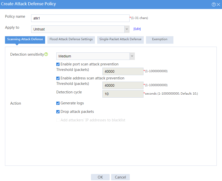
# Click OK.
The attack defense policy is displayed on the attack defense policy list, as shown in Figure 3.
Figure 3 Attack defense policy list
![]()
Verifying the configuration
1. On the host at 20.1.1.2, simulate an attack to send a large number of SYN packets with different destination port numbers to destination address 30.1.1.2.
2. On the device, view the attack defense log information.
# On the top navigation bar, click Monitor.
# From the navigation pane, select Security Logs > Scanning Attack Logs.
Figure 4 Scanning attack log list

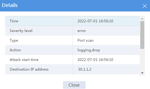
3. Double-click the attack log to view its details.
Figure 5 Detailed information about the scanning attack log
4. Verify that no sessions are created for SYN packets because these packets have been dropped.
# On the top navigation bar, click Monitor.
# From the navigation pane, select Sessions.
Network configuration
As shown in Figure 6, configure SYN flood attack detection and defense on the security zone where GigabitEthernet 1/0/1 resides to protect internal network hosts from SYN flood attacks. When the device detects that the number of packets sent by the attacker reaches or exceeds 10000 per second, the device outputs logs and drops attack packets.

Software versions used
This configuration example was created and verified on E8371 of the F5000-AI160 device and E9671 of the M9000-X06 device.
Procedure
1. Assign IP addresses to interfaces and add the interfaces to security zones.
# On the top navigation bar, click Network.
# From the navigation pane, select Interface Configuration > Interfaces.
# Click the Edit icon for GE 1/0/1.
# In the dialog box that opens, configure the interface:
a. Select the Untrust security zone.
b. On the IPv4 Address tab, enter the IP address and mask of the interface. In this example, enter 20.1.1.1/24.
c. Click OK.
# Add GE 1/0/3 to the Trust security zone and set its IP address to 30.1.1.1/24 in the same way you configure GE 1/0/1.
2. Create a security policy from zone Untrust to zone Trust.
# On the top navigation bar, click Policies.
# From the navigation pane, select Security Policies > Security Policies.
# Click Create.
# In the dialog box that opens, configure a security policy:
¡ Enter policy name Secpolicy.
¡ Select source zone Untrust.
¡ Select destination zone Trust.
¡ Select type IPv4.
¡ Set the action to Permit.
¡ Specify 20.1.1.0/24 as the source IPv4 address.
¡ Specify 30.1.1.0/24 as the destination IPv4 address.
¡ Use the default settings for other parameters.
# Click OK.
3. Configuring flood attack defense global settings.
# On the top navigation bar, click Objects.
# From the navigation pane, select Attack Defense Policies.
# Click Create.
# In the dialog box that opens, create an attack defense policy, as shown in Figure 7.
Figure 7 Creating an attack defense policy
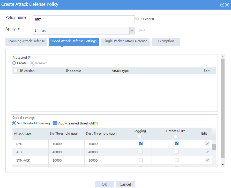
# Click the Edit icon for an attack type.
# In the dialog box that opens, edit the flood attack defense global settings, as shown in Figure 8.
Figure 8 Editing flood attack defense global settings
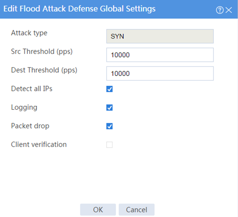
# Click OK.
The attack defense policy is displayed on the attack defense policy list, as shown in Figure 9.
Figure 9 Attack defense policy list
![]()
Verifying the configuration
1. On the host at 20.1.1.2, simulate a SYN flood attack by sending a large number of SYN packets with different source port numbers to destination address 30.1.1.2.
2. On the device, view the flood attack log information.
# On the top navigation bar, click Monitor.
# From the navigation pane, select Security Logs > Flood Attack Logs.
Figure 10 Flood attack log list

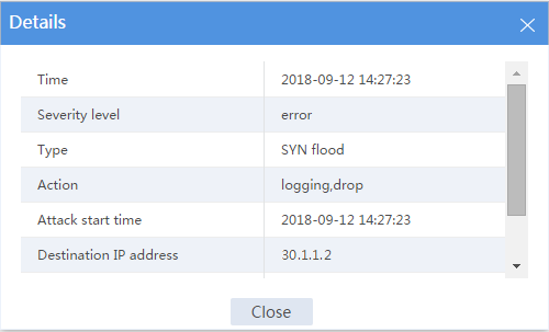
3. Double-click the flood attack log to view its details.
Figure 11 Flood attack log details
4. Verify that no session is created for SYN packets because these packets have been dropped.
# On the top navigation bar, click Monitor.
# From the navigation pane, select Device Logs > Traffic Logs.
