- Table of Contents
-
- H3C SecPath M9000 Multi Service Security Gateway Configuration Examples(V7)(E9X71)-6W700
- 00-Preface
- 01-About the configuration examples
- 02-Web Login Configuration Examples
- 03-Internet Access Through a Static IP Address Configuration Examples
- 04-Internet access through PPPoE configuration examples
- 05-License Configuration Examples
- 06-Signature Library Upgrade Configuration Examples
- 07-Software Upgrade Examples
- 08-Routing deployment configuration examples
- 09-Transparent deployment configuration examples
- 10-Static routing configuration examples
- 11-RIP configuration examples
- 12-OSPF configuration examples
- 13-BGP configuration examples
- 14-Policy-based routing configuration examples
- 15-Security Policy Configuration Examples
- 16-APR-Based Security Policy Configuration Examples
- 17-Object Group Configuration Examples
- 18-User identification configuration examples
- 19-Attack defense configuration examples
- 20-Request Limit Configuration Examples
- 21-IPS Configuration Examples
- 22-URL Filtering Configuration Examples
- 23-Anti-Virus Configuration Examples
- 24-File Filtering Configuration Examples
- 25-Data Filtering Configuration Examples
- 26-WAF Configuration Examples
- 27-IP Reputation Configuration Examples
- 28-APT Defense Configuration Examples
- 29-NetShare Control Configuration Examples
- 30-Bandwidth Management Configuration Examples
- 31-IPsec configuration examples
- 32-SSL VPN IP access configuration examples
- 32-SSL VPN TCP access configuration examples
- 32-SSL VPN Web access configuration examples
- 33-L2TP Configuration Examples
- 34-NAT configuration examples
- 35-NPTv6 Configuration Examples
- 36-Policy-based NAT configuration examples
- 37-NAT hairpin configuration examples
- 38-NAT Flow Logging Configuration Examples
- 39-Inbound Link Load Balancing Configuration Examples
- 40-Outbound Link Load Balancing Configuration Examples
- 41-Server Load Balancing Configuration Examples
- 42-Transparent DNS Proxy Configuration Examples
- 43-Hot Backup Configuration Examples
- 44-Context Configuration Examples
- 45-DNS configuration examples
- 46-Server Connection Detection Configuration Examples
- 47-Connection Limit Configuration Examples
- 48-Public key management configuration examples
- 49-SSL Decryption Configuration Examples
- 50-MAC Address Learning Through a Layer 3 Device Configuration Examples
- 51-4G Configuration Examples
- 52-WLAN Configuration Examples
- Related Documents
-
| Title | Size | Download |
|---|---|---|
| 43-Hot Backup Configuration Examples | 809.04 KB |
Hot backup configuration examples
Contents
· Example: Configuring hot backup in active/standby mode in collaboration with VRRP (IPv4)
· Example: Configuring hot backup in dual-active mode in collaboration with VRRP (IPv4)
· Example: Configuring hot backup in dual-active mode in collaboration with a routing protocol (IPv4)
· Example: Configuring a transparent in-path hot backup system in active/standby mode (IPv4)
· Example: Configuring a transparent in-path hot backup system in dual-active mode (IPv4)
· Example: Configuring hot backup in active/standby mode in collaboration with VRRP (IPv6)
· Example: Configuring hot backup in dual-active mode in collaboration with a routing protocol (IPv6)
The following information provides RBM-based hot backup configuration examples.
This document is not restricted to specific software or hardware versions. Procedures and information in the examples might be slightly different depending on the software or hardware version of the device.
The configuration examples were created and verified in a lab environment, and all the devices were started with the factory default configuration. When you are working on a live network, make sure you understand the potential impact of every command on your network.
The following information is provided based on the assumption that you have basic knowledge of the RBM, VRRP, and Track features.
Verify that the devices to be assigned to a hot backup system meet the hardware and software environment consistency requirements in this section.
Hardware environment consistency
Before you configure a hot backup system, verify that the following hardware settings are the same on the devices to be assigned to the hot backup system:
· Device model.
· Location, number, and type of MPUs.
· Location, number, and type of service modules.
· Location, number, and type of switching fabric modules.
· Location, number, and type of interface modules.
· Number and type of management interfaces, service interfaces, interfaces for setting up the control channel, and interfaces for setting up the data channel. Do not use one interface for multiple purposes.
· Location, number, and type of disks. A device without disks installed has small log storage and does not support some types of logs or reports.
Software environment consistency
Before you configure a hot backup system, verify that the following software settings are the same on the devices to be assigned to the hot backup system:
· Software environment and version, including boot packages, system packages, feature packages, and patches.
· Licensed signature libraries and features, such as signature library types, signature library version, validation time, and number of licensed resources.
· Interface numbers.
· Type, speed, and number of the interfaces for setting up the control channel. As a best practice, use aggregate interfaces.
· Type, speed, and number of the interfaces for setting up the data channel. As a best practice, use aggregate interfaces.
· Aggregate interface numbers and aggregation member port numbers.
· Security zone configuration on the interfaces at the same location.
Feature compatibility restrictions
Compatibility with NAT
If you configure both VRRP and NAT on a hot backup system, you must associate NAT configuration with VRRP groups, such as NAT rules, source translation methods, and NAT server mappings. If you fail to do so, NAT cannot operate correctly.
Compatibility with SSL VPN
For SSL VPN to operate correctly on a hot backup system, you must configure the port used for transmitting user data for the hot backup system on the global setting configuration page of SSL VPN.
You can use SSL VPN only when the hot backup system is operating in active/standby mode and collaborating with VRRP. You cannot use SSL VPN in any other scenario.
Compatibility with application security
If asymmetric-path traffic exists on the transparent in-path hot backup operating in dual-active mode, enable DPI services to support the hot backup feature on the advanced setting configuration page of application security. If you fail to do so, application security services cannot identify or process traffic correctly.
Network configuration
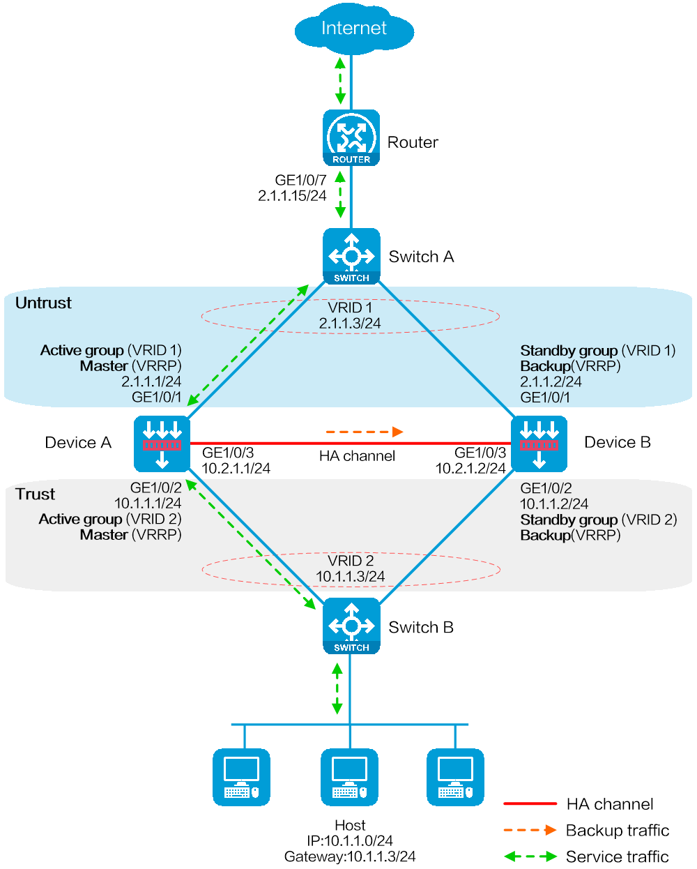
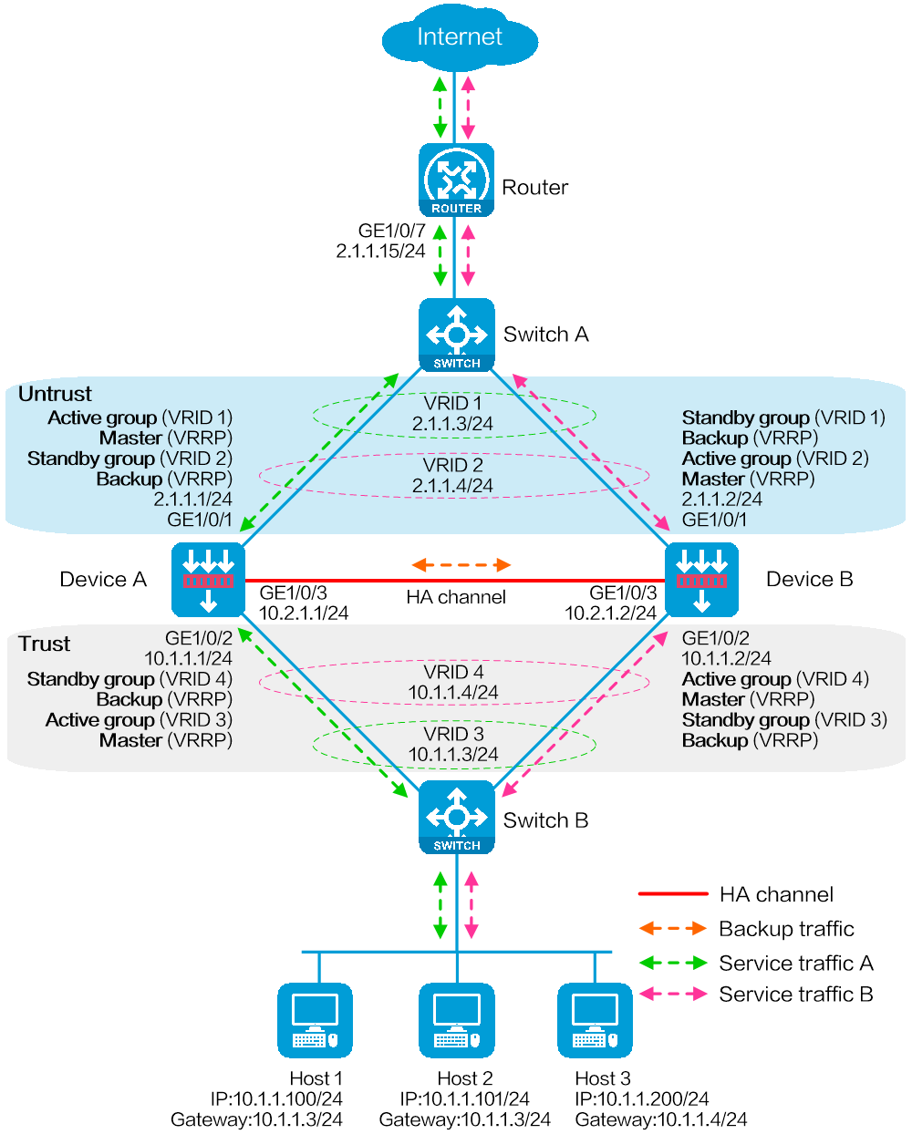
As shown in Figure 1, set up a hot backup system at the border between the Internet and the internal network of an enterprise to ensure service continuity.
· Configure the hot backup system to collaborate with VRRP.
· Configure the hot backup system to operate in active/standby mode.
· Configure Device A and Device B as the primary device and the secondary device, respectively.
Software versions used
This configuration example was created and verified on E8371 of the F5000-AI160 device.
This configuration example was created and verified on E9671 of the M9000-X06 device.
Procedure
Configuring Switch A
# Create VLAN 10.
# Configure the interfaces attached to the hot backup system and the router to operate at Layer 2. Assign them to VLAN 10 as access interfaces.
Configuring Switch B
# Create VLAN 10.
# Configure the interfaces attached to the hot backup system and the host to operate at Layer 2. Assign them to VLAN 10 as access interfaces.
Configuring the router
# Assign 2.1.1.15/24 to GigabitEthernet 1/0/7.
# Configure routes as follows:
· Specify 2.1.1.3 (virtual IP address of VRRP group 1) as the next hop of the routes to the internal network.
· Specify the IP address of the peer interface attached to the traffic outgoing interface as the next hop of the route to the Internet.
Configuring Device A
Configuring basic network settings
1. Assign IP addresses to interfaces:
# On the top navigation bar, click Network.
# From the navigation pane, select Interface Configuration > Interfaces.
# Click the Edit icon for GE 1/0/1.
# In the dialog box that opens, configure the interface:
a. On the Basic Configuration tab, select the Untrust security zone.
b. On the IPv4 Address tab, enter the IP address and mask of the interface. In this example, enter 2.1.1.1/24.
c. Use the default settings for other parameters.
d. Click OK.
# Add GE 1/0/2 to the Trust security zone and assign 10.1.1.1/24 to it in the same way you configure GE 1/0/1.
# Assign 10.2.1.1/24 to GE 1/0/3 in the same way you configure GE 1/0/1.
2. Configure routing:
This step uses static routing as an example. To use dynamic routing, configure a dynamic routing protocol.
# On the top navigation bar, click Network.
# From the navigation pane, select Routing > Static Routing.
# On the IPv4 Static Routing tab, click Create.
# In the dialog box that opens, configure an IPv4 static route:
a. Enter destination IP address 0.0.0.0.
b. Enter mask length 0.
c. Enter next hop address 2.1.1.15.
d. Use the default settings for other parameters.
e. Click OK.
3. Configure a security policy to permit service traffic:
Perform this task only on the primary device. The secondary device will synchronize security policy configuration with the primary device after the hot backup system is set up.
# On the top navigation bar, click Policies.
# From the navigation pane, select Security Policies > Security Policies.
# Select Create > Create a policy.
# In the dialog box that opens, configure a security policy to permit traffic from zone Trust to zone Untrust:
a. Enter security policy name Trust-Untrust.
b. Select source zone Trust.
c. Select destination zone Untrust.
d. Select IP version IPv4.
e. Set the action to Permit.
f. Enter source IP address 10.1.1.0/24.
g. Use the default settings for other parameters.
h. Click OK.
4. Configure security policies to permit VRRP protocol packets:
This task allows Device A and Device B to exchange VRRP packets and elect a VRRP master when the RBM channels are disconnected.
Perform this task only on the primary device. The secondary device will synchronize security policy configuration with the primary device after the hot backup system is set up.
# On the top navigation bar, click Policies.
# From the navigation pane, select Security Policies > Security Policies.
# Select Create > Create a policy.
# In the dialog box that opens, configure a security policy to permit traffic from zone Trust to zone Local:
a. Enter security policy name vrrp1.
b. Select source zone Trust.
c. Select destination zone Local.
d. Select IP version IPv4.
e. Set the action to Permit.
f. Select policy group vrrp.
g. Use the default settings for other parameters.
h. Click OK.
# Configure a security policy to permit traffic from zone Local to zone Trust:
i. Enter security policy name vrrp2.
j. Select source zone Local.
k. Select destination zone Trust.
l. Select IP version IPv4.
m. Set the action to Permit.
n. Select policy group vrrp.
o. Use the default settings for other parameters.
p. Click OK.
# Configure a security policy to permit traffic from zone Untrust to zone Local:
q. Enter security policy name vrrp3.
r. Select source zone Untrust.
s. Select destination zone Local.
t. Select IP version IPv4.
u. Set the action to Permit.
v. Select policy group vrrp.
w. Use the default settings for other parameters.
x. Click OK.
# Configure a security policy to permit traffic from zone Local to zone Untrust:
y. Enter security policy name vrrp4.
z. Select source zone Local.
aa. Select destination zone Untrust.
bb. Select IP version IPv4.
cc. Set the action to Permit.
dd. Select policy group vrrp.
ee. Use the default settings for other parameters.
ff. Click OK.
Configuring hot backup settings
# On the top navigation bar, click System.
# From the navigation pane, select High Availability > Hot Backup.
# Click Configure.
# Configure the hot backup parameters as shown in Figure 2.
Figure 2 Configuring hot backup parameters

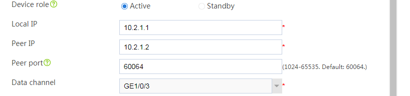

# Click OK.
Associating the hot backup system with VRRP
# On the top navigation bar, click System.
# From the navigation pane, select High Availability > VRRP.
# Click Create.
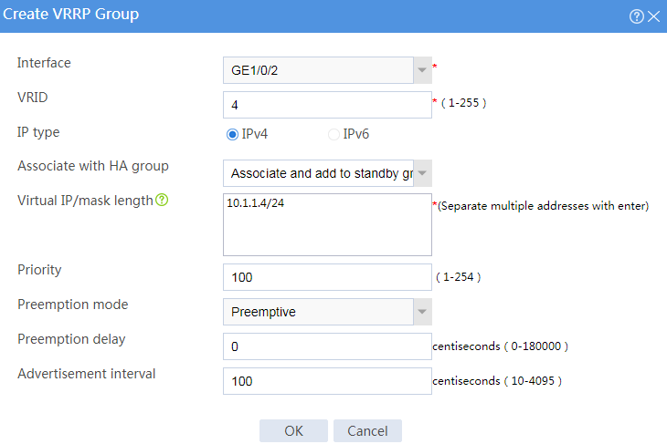
# Configure VRRP groups as shown in the follow figures.
Figure 3 Creating VRRP group 1
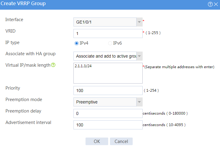
Figure 4 Creating VRRP group 2
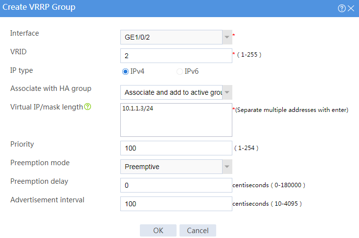
# Click OK.
Configuring security services
# Configure security devices on the hot backup member devices. If the hot backup system can back up configuration for a module, configure the module only on the primary device (Device A).
Configuring Device B
Configuring basic network settings
1. Assign IP addresses to interfaces:
# On the top navigation bar, click Network.
# From the navigation pane, select Interface Configuration > Interfaces.
# Click the Edit icon for GE 1/0/1.
# In the dialog box that opens, configure the interface:
a. On the Basic Configuration tab, select the Untrust security zone.
b. On the IPv4 Address tab, enter the IP address and mask of the interface. In this example, enter 2.1.1.2/24.
c. Use the default settings for other parameters.
d. Click OK.
# Add GE 1/0/2 to the Trust security zone and assign 10.1.1.2/24 to it in the same way you configure GE 1/0/1.
# Assign 10.2.1.2/24 to GE 1/0/3 in the same way you configure GE 1/0/1.
2. Configure routing:
This step uses static routing as an example. To use dynamic routing, configure a dynamic routing protocol.
# On the top navigation bar, click Network.
# From the navigation pane, select Routing > Static Routing.
# On the IPv4 Static Routing tab, click Create.
# In the dialog box that opens, configure an IPv4 static route:
a. Enter destination IP address 0.0.0.0.
b. Enter mask length 0.
c. Enter next hop address 2.1.1.15.
d. Use the default settings for other parameters.
e. Click OK.
Configuring hot backup settings
# On the top navigation bar, click System.
# From the navigation pane, select High Availability > Hot Backup.
# Click Configure.
# Configure the hot backup parameters as shown in Figure 5.
Figure 5 Configuring hot backup parameters


# Click OK.
Associating the hot backup system with VRRP
# On the top navigation bar, click System.
# From the navigation pane, select High Availability > VRRP.
# Click Create.
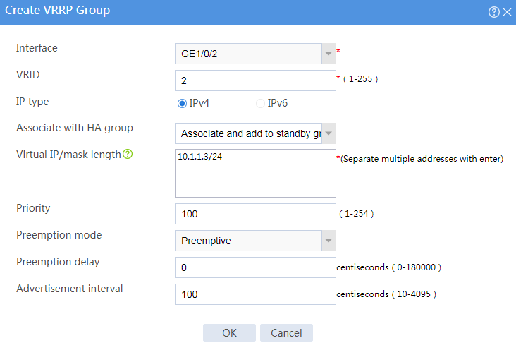
# Configure VRRP groups as shown in the follow figures.
Figure 6 Creating VRRP group 1
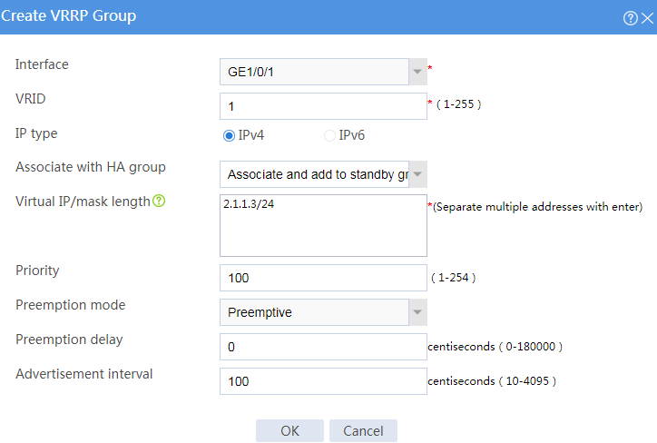
Figure 7 Creating VRRP group 2
# Click OK.
Configuring the host
# On the host, specify 10.1.1.3 (virtual IP address of VRRP group 2) as the default gateway.
Verifying the configuration
# Enable logging for the interzone policy that permits communication between security zones Trust and Untrust. Verity that only Device A generates log messages when the host communicates with the Internet.
Network configuration
As shown in Figure 8, set up a hot backup system at the border between the Internet and the internal network of an enterprise to ensure service continuity.
· Configure the hot backup system to collaborate with VRRP.
· Configure the hot backup system to operate in dual-active mode.
· Configure Device A and Device B to load share traffic.
Software versions used
This configuration example was created and verified on E8371 of the F5000-AI160 device.
This configuration example was created and verified on E9671 of the M9000-X06 device.
Procedure
Configuring Switch A
# Create VLAN 10.
# Configure the interfaces attached to the hot backup system and the router to operate at Layer 2. Assign them to VLAN 10 as access interfaces.
Configuring Switch B
# Create VLAN 10.
# Configure the interfaces attached to the hot backup system and the host to operate at Layer 2. Assign them to VLAN 10 as access interfaces.
Configuring the router
# Assign 2.1.1.15/24 to GigabitEthernet 1/0/7.
# Specify 2.1.1.3 (virtual IP address of VRRP group 1) as the next hop of the routes to some subnets of the internal network. Specify 2.1.1.4 (virtual IP address of VRRP group 2) as the next hop of the routes to the other subnets of the internal network.
# Specify the IP address of the peer interface attached to the traffic outgoing interface as the next hop of the route to the Internet.
Configuring Device A
Configuring basic network settings
1. Assign IP addresses to interfaces:
# On the top navigation bar, click Network.
# From the navigation pane, select Interface Configuration > Interfaces.
# Click the Edit icon for GE 1/0/1.
# In the dialog box that opens, configure the interface:
a. On the Basic Configuration tab, select the Untrust security zone.
b. On the IPv4 Address tab, enter the IP address and mask of the interface. In this example, enter 2.1.1.1/24.
c. Use the default settings for other parameters.
d. Click OK.
# Add GE 1/0/2 to the Trust security zone and assign 10.1.1.1/24 to it in the same way you configure GE 1/0/1.
# Assign 10.2.1.1/24 to GE 1/0/3 in the same way you configure GE 1/0/1.
2. Configure routing:
This step uses static routing as an example. To use dynamic routing, configure a dynamic routing protocol.
# On the top navigation bar, click Network.
# From the navigation pane, select Routing > Static Routing.
# On the IPv4 Static Routing tab, click Create.
# In the dialog box that opens, configure an IPv4 static route:
a. Enter destination IP address 0.0.0.0.
b. Enter mask length 0.
c. Enter next hop address 2.1.1.15.
d. Use the default settings for other parameters.
e. Click OK.
3. Configure a security policy to permit service traffic:
Perform this task only on the primary device. The secondary device will synchronize security policy configuration with the primary device after the hot backup system is set up.
# On the top navigation bar, click Policies.
# From the navigation pane, select Security Policies > Security Policies.
# Select Create > Create a policy.
# In the dialog box that opens, configure a security policy to permit traffic from zone Trust to zone Untrust:
a. Enter security policy name Trust-Untrust.
b. Select source zone Trust.
c. Select destination zone Untrust.
d. Select IP version IPv4.
e. Set the action to Permit.
f. Enter source IP address 10.1.1.0/24.
g. Use the default settings for other parameters.
h. Click OK.
4. Configure security policies to permit VRRP protocol packets:
This task allows Device A and Device B to exchange VRRP packets and elect a VRRP master when the RBM channels are disconnected.
Perform this task only on the primary device. The secondary device will synchronize security policy configuration with the primary device after the hot backup system is set up.
# On the top navigation bar, click Policies.
# From the navigation pane, select Security Policies > Security Policies.
# Select Create > Create a policy.
# In the dialog box that opens, configure a security policy to permit traffic from zone Trust to zone Local:
a. Enter security policy name vrrp1.
b. Select source zone Trust.
c. Select destination zone Local.
d. Select IP version IPv4.
e. Set the action to Permit.
f. Select policy group vrrp.
g. Use the default settings for other parameters.
h. Click OK.
# Configure a security policy to permit traffic from zone Local to zone Trust:
i. Enter security policy name vrrp2.
j. Select source zone Local.
k. Select destination zone Trust.
l. Select IP version IPv4.
m. Set the action to Permit.
n. Select policy group vrrp.
o. Use the default settings for other parameters.
p. Click OK.
# Configure a security policy to permit traffic from zone Untrust to zone Local:
q. Enter security policy name vrrp3.
r. Select source zone Untrust.
s. Select destination zone Local.
t. Select IP version IPv4.
u. Set the action to Permit.
v. Select policy group vrrp.
w. Use the default settings for other parameters.
x. Click OK.
# Configure a security policy to permit traffic from zone Local to zone Untrust:
y. Enter security policy name vrrp4.
z. Select source zone Local.
aa. Select destination zone Untrust.
bb. Select IP version IPv4.
cc. Set the action to Permit.
dd. Select policy group vrrp.
ee. Use the default settings for other parameters.
ff. Click OK.
Configuring hot backup settings
# On the top navigation bar, click System.
# From the navigation pane, select High Availability > Hot Backup.
# Click Configure.
# Configure the hot backup parameters as shown in Figure 9.
Figure 9 Configuring hot backup parameters


# Click OK.
Associating the hot backup system with VRRP
# On the top navigation bar, click System.
# From the navigation pane, select High Availability > VRRP.
# Click Create.
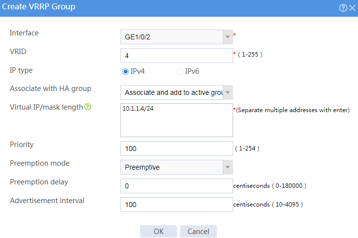
# Configure VRRP groups as shown in the follow figures.
Figure 10 Creating VRRP group 1

Figure 11 Creating VRRP group 2
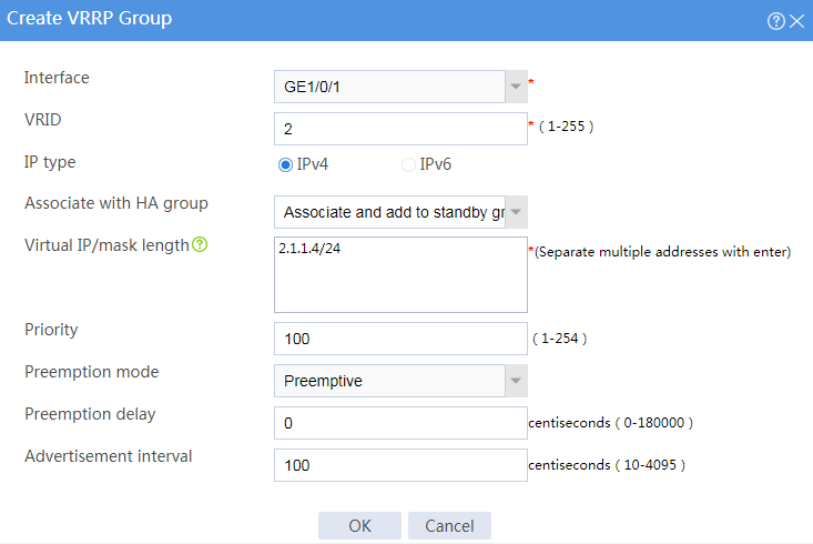
Figure 12 Creating VRRP group 3
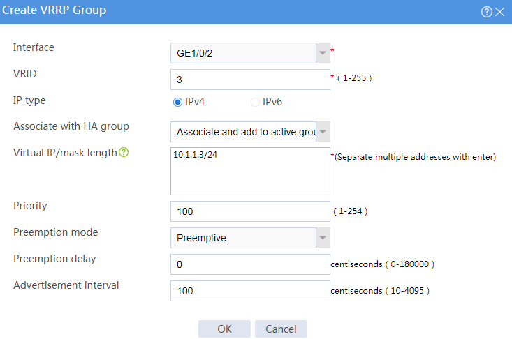
Figure 13 Creating VRRP group 4
# Click OK.
Configuring security services
# Configure security devices on the hot backup member devices. If the hot backup system can back up configuration for a module, configure the module only on the primary device (Device A).
Configuring Device B
Configuring basic network settings
1. Assign IP addresses to interfaces:
# On the top navigation bar, click Network.
# From the navigation pane, select Interface Configuration > Interfaces.
# Click the Edit icon for GE 1/0/1.
# In the dialog box that opens, configure the interface:
a. On the Basic Configuration tab, select the Untrust security zone.
b. On the IPv4 Address tab, enter the IP address and mask of the interface. In this example, enter 2.1.1.2/24.
c. Use the default settings for other parameters.
d. Click OK.
# Add GE 1/0/2 to the Trust security zone and assign 10.1.1.2/24 to it in the same way you configure GE 1/0/1.
# Assign 10.2.1.2/24 to GE 1/0/3 in the same way you configure GE 1/0/1.
2. Configure routing:
This step uses static routing as an example. To use dynamic routing, configure a dynamic routing protocol.
# On the top navigation bar, click Network.
# From the navigation pane, select Routing > Static Routing.
# On the IPv4 Static Routing tab, click Create.
# In the dialog box that opens, configure an IPv4 static route:
a. Enter destination IP address 0.0.0.0.
b. Enter mask length 0.
c. Enter next hop address 2.1.1.15.
d. Use the default settings for other parameters.
e. Click OK.
Configuring hot backup settings
# On the top navigation bar, click System.
# From the navigation pane, select High Availability > Hot Backup.
# Click Configure.
# Configure the hot backup parameters as shown in Figure 14.
Figure 14 Configuring hot backup parameters


# Click OK.
Associating the hot backup system with VRRP
# On the top navigation bar, click System.
# From the navigation pane, select High Availability > VRRP.
# Click Create.
# Configure VRRP groups as shown in the follow figures.
Figure 15 Creating VRRP group 1

Figure 16 Creating VRRP group 2
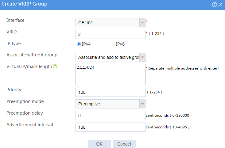
Figure 17 Creating VRRP group 3

Figure 18 Creating VRRP group 4
# Click OK.
Configuring the hosts
# On some hosts, specify 10.1.1.3 (virtual IP address of VRRP group 3) as the default gateway. On the other hosts, specify 10.1.1.4 (virtual IP address of VRRP group 4) as the default gateway.
Verifying the configuration
# Enable logging for the interzone policy that permits communication between security zones Trust and Untrust. Verity that only Device A generates log messages when a host for which Device A forwards traffic communicates with the Internet. Verity that only Device B generates log messages when a host for which Device B forwards traffic communicates with the Internet.
Network configuration
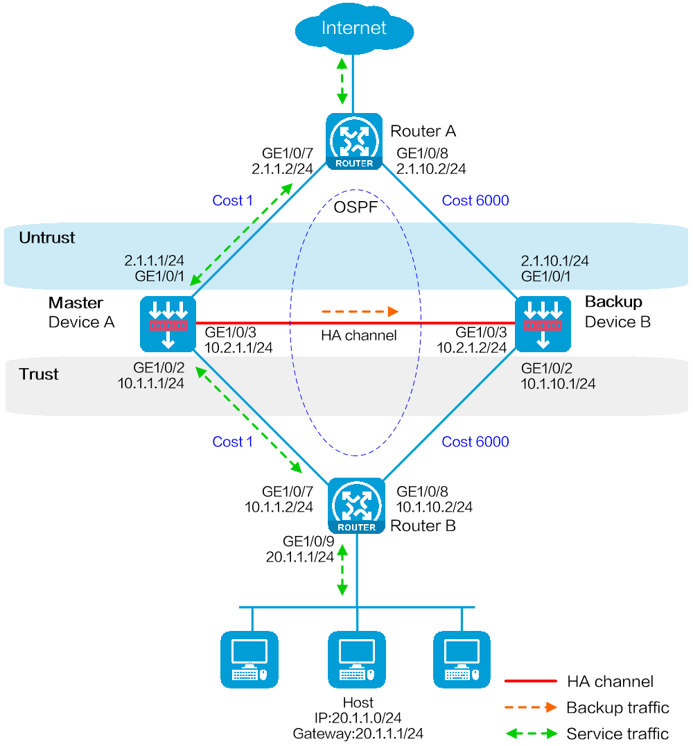
As shown in Figure 19, set up a hot backup system at the border between the Internet and the internal network of an enterprise to ensure service continuity.
· Configure the hot backup system to collaborate with OSPF.
· Configure the hot backup system to operate in active/standby mode.
· Configure Device A and Device B as the primary device and the secondary device, respectively.
Software versions used
This configuration example was created and verified on E8371 of the F5000-AI160 device.
This configuration example was created and verified on E9671 of the M9000-X06 device.
Procedure
Configuring Router A
# Assign 2.1.1.2/24 to GigabitEthernet 1/0/7.
# Assign 2.1.10.2/24 to GigabitEthernet 1/0/8.
# Configure OSPF for Router A to have Layer 3 reachability to other devices.
Configuring Router B
# Assign 10.1.1.2/24 to GigabitEthernet 1/0/7.
# Assign 10.1.10.2/24 to GigabitEthernet 1/0/8.
# Configure OSPF for Router B to have Layer 3 reachability to other devices.
Configuring Device A
Configuring basic network settings
1. Assign IP addresses to interfaces:
# On the top navigation bar, click Network.
# From the navigation pane, select Interface Configuration > Interfaces.
# Click the Edit icon for GE 1/0/1.
# In the dialog box that opens, configure the interface:
a. On the Basic Configuration tab, select the Untrust security zone.
b. On the IPv4 Address tab, enter the IP address and mask of the interface. In this example, enter 2.1.1.1/24.
c. Use the default settings for other parameters.
d. Click OK.
# Add GE 1/0/2 to the Trust security zone and assign 10.1.1.1/24 to it in the same way you configure GE 1/0/1.
# Assign 10.2.1.1/24 to GE 1/0/3 in the same way you configure GE 1/0/1.
2. Configure routing:
This step uses OSPF as an example. You can configure another dynamic routing protocol as needed.
# On the top navigation bar, click Network.
# From the navigation pane, select Routing > OSPF.
# Click Create.
# In the dialog box that opens, configure an OSPF instance:
a. Select version OSPFv2.
b. Enter instance name 1.
c. Enter router ID 2.1.1.1.
d. Use the default settings for other parameters.
e. Click OK.
# Click 0 in the Number of OSPF areas column for the created OSPF instance.
# On the OSPF area configuration page that opens, click Create.
# In the dialog box that opens, configure an area:
f. Enter area ID 0.0.0.0.
g. Add subnets 2.1.1.0/24 and 10.1.1.0/24.
h. Use the default settings for other parameters.
i. Click OK.
3. Configure a security policy to permit service traffic:
Perform this task only on the primary device. The secondary device will synchronize security policy configuration with the primary device after the hot backup system is set up.
# On the top navigation bar, click Policies.
# From the navigation pane, select Security Policies > Security Policies.
# Select Create > Create a policy.
# In the dialog box that opens, configure a security policy to permit traffic from zone Trust to zone Untrust:
a. Enter security policy name Trust-Untrust.
b. Select source zone Trust.
c. Select destination zone Untrust.
d. Select IP version IPv4.
e. Set the action to Permit.
f. Enter source IP address 20.1.1.0/24.
g. Use the default settings for other parameters.
h. Click OK.
4. Configure security policies to permit OSPF protocol packets:
Perform this task only on the primary device. The secondary device will synchronize security policy configuration with the primary device after the hot backup system is set up.
# On the top navigation bar, click Policies.
# From the navigation pane, select Security Policies > Security Policies.
# Select Create > Create a policy.
# In the dialog box that opens, configure a security policy to permit traffic from zone Trust to zone Local:
a. Enter security policy name ospf1.
b. Select source zone Trust.
c. Select destination zone Local.
d. Select IP version IPv4.
e. Set the action to Permit.
f. Select policy group ospf.
g. Use the default settings for other parameters.
h. Click OK.
# Configure a security policy to permit traffic from zone Local to zone Trust:
i. Enter security policy name ospf2.
j. Select source zone Local.
k. Select destination zone Trust.
l. Select IP version IPv4.
m. Set the action to Permit.
n. Select policy group ospf.
o. Use the default settings for other parameters.
p. Click OK.
# Configure a security policy to permit traffic from zone Untrust to zone Local:
q. Enter security policy name ospf3.
r. Select source zone Untrust.
s. Select destination zone Local.
t. Select IP version IPv4.
u. Set the action to Permit.
v. Select policy group ospf.
w. Use the default settings for other parameters.
x. Click OK.
# Configure a security policy to permit traffic from zone Local to zone Untrust:
y. Enter security policy name ospf4.
z. Select source zone Local.
aa. Select destination zone Untrust.
bb. Select IP version IPv4.
cc. Set the action to Permit.
dd. Select policy group ospf.
ee. Use the default settings for other parameters.
ff. Click OK.
Configuring hot backup settings
# On the top navigation bar, click System.
# From the navigation pane, select High Availability > Track.
# Click Add.
# Configure a track entry:
1. Enter track entry ID 1.
2. Select the interface module.
3. Select GE 1/0/1 as the monitored interface.
4. Use the default settings for other parameters.
# Configure track entry 2 to monitor the state of GE 1/0/2. (Details not shown.)
# On the top navigation bar, click System.
# From the navigation pane, select High Availability > Hot Backup.
# Click Configure.
# Configure the hot backup parameters as shown in Figure 20.
Figure 20 Configuring hot backup parameters


# Click OK.
Configuring security services
# Configure security devices on the hot backup member devices. If the hot backup system can back up configuration for a module, configure the module only on the primary device (Device A).
Configuring Device B
Configuring basic network settings
1. Assign IP addresses to interfaces:
# On the top navigation bar, click Network.
# From the navigation pane, select Interface Configuration > Interfaces.
# Click the Edit icon for GE 1/0/1.
# In the dialog box that opens, configure the interface:
a. On the Basic Configuration tab, select the Untrust security zone.
b. On the IPv4 Address tab, enter the IP address and mask of the interface. In this example, enter 2.1.10.1/24.
c. Use the default settings for other parameters.
d. Click OK.
# Add GE 1/0/2 to the Trust security zone and assign 10.1.10.1/24 to it in the same way you configure GE 1/0/1.
# Assign 10.2.1.2/24 to GE 1/0/3 in the same way you configure GE 1/0/1.
2. Configure routing:
This step uses OSPF as an example. You can configure another dynamic routing protocol as needed.
# On the top navigation bar, click Network.
# From the navigation pane, select Routing > OSPF.
# Click Create.
# In the dialog box that opens, configure an OSPF instance:
a. Select version OSPFv2.
b. Enter instance name 1.
c. Enter router ID 2.1.10.1.
d. Use the default settings for other parameters.
e. Click OK.
# Click 0 in the Number of OSPF areas column for the created OSPF instance.
# On the OSPF area configuration page that opens, click Create.
# In the dialog box that opens, configure an area:
f. Enter area ID 0.0.0.0.
g. Add subnets 2.1.10.0/24 and 10.1.10.0/24.
h. Use the default settings for other parameters.
i. Click OK.
Configuring hot backup settings
# On the top navigation bar, click System.
# From the navigation pane, select High Availability > Track.
# Click Add.
# Configure a track entry:
1. Enter track entry ID 1.
2. Select the interface module.
3. Select GE 1/0/1 as the monitored interface.
4. Use the default settings for other parameters.
# Configure track entry 2 to monitor the state of GE 1/0/2. (Details not shown.)
# On the top navigation bar, click System.
# From the navigation pane, select High Availability > Hot Backup.
# Click Configure.
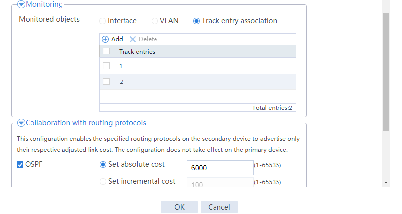
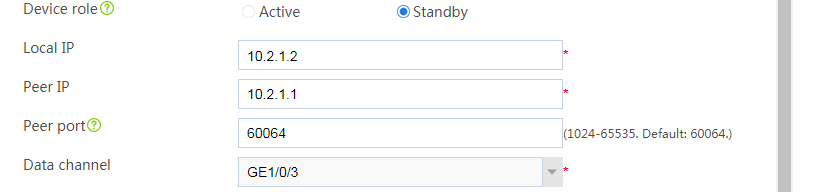
# Configure the hot backup parameters as shown in Figure 21.
Figure 21 Configuring hot backup parameters


# Click OK.
Configuring the host
# On the host, specify 20.1.1.1 as the default gateway.
Verifying the configuration
# Enable logging for the interzone policy that permits communication between security zones Trust and Untrust. Verity that only Device A generates log messages when the host communicates with the Internet.
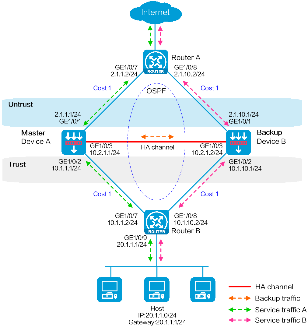
Network configuration
As shown in Figure 22, set up a hot backup system at the border between the Internet and the internal network of an enterprise to ensure service continuity.
· Configure the hot backup system to collaborate with OSPF.
· Configure the hot backup system to operate in dual-active mode.
· Configure Device A and Device B to load share traffic.
Software versions used
This configuration example was created and verified on E8371 of the F5000-AI160 device.
This configuration example was created and verified on E9671 of the M9000-X06 device.
Procedure
Configuring Router A
# Assign 2.1.1.2/24 to GigabitEthernet 1/0/7.
# Assign 2.1.10.2/24 to GigabitEthernet 1/0/8.
# Configure OSPF for Router A to have Layer 3 reachability to other devices.
# Configure per-flow load sharing for IP forwarding.
Configuring Router B
# Assign 10.1.1.2/24 to GigabitEthernet 1/0/7.
# Assign 10.1.10.2/24 to GigabitEthernet 1/0/8.
# Configure OSPF for Router B to have Layer 3 reachability to other devices.
# Configure per-flow load sharing for IP forwarding.
Configuring Device A
Configuring basic network settings
1. Assign IP addresses to interfaces:
# On the top navigation bar, click Network.
# From the navigation pane, select Interface Configuration > Interfaces.
# Click the Edit icon for GE 1/0/1.
# In the dialog box that opens, configure the interface:
a. On the Basic Configuration tab, select the Untrust security zone.
b. On the IPv4 Address tab, enter the IP address and mask of the interface. In this example, enter 2.1.1.1/24.
c. Use the default settings for other parameters.
d. Click OK.
# Add GE 1/0/2 to the Trust security zone and assign 10.1.1.1/24 to it in the same way you configure GE 1/0/1.
# Assign 10.2.1.1/24 to GE 1/0/3 in the same way you configure GE 1/0/1.
2. Configure routing:
This step uses OSPF as an example. You can configure another dynamic routing protocol as needed.
# On the top navigation bar, click Network.
# From the navigation pane, select Routing > OSPF.
# Click Create.
# In the dialog box that opens, configure an OSPF instance:
a. Select version OSPFv2.
b. Enter instance name 1.
c. Enter router ID 2.1.1.1.
d. Use the default settings for other parameters.
e. Click OK.
# Click 0 in the Number of OSPF areas column for the created OSPF instance.
# On the OSPF area configuration page that opens, click Create.
# In the dialog box that opens, configure an area:
f. Enter area ID 0.0.0.0.
g. Add subnets 2.1.1.0/24 and 10.1.1.0/24.
h. Use the default settings for other parameters.
i. Click OK.
3. Configure a security policy to permit service traffic:
Perform this task only on the primary device. The secondary device will synchronize security policy configuration with the primary device after the hot backup system is set up.
# On the top navigation bar, click Policies.
# From the navigation pane, select Security Policies > Security Policies.
# Select Create > Create a policy.
# In the dialog box that opens, configure a security policy to permit traffic from zone Trust to zone Untrust:
a. Enter security policy name Trust-Untrust.
b. Select source zone Trust.
c. Select destination zone Untrust.
d. Select IP version IPv4.
e. Set the action to Permit.
f. Enter source IP address 20.1.1.0/24.
g. Use the default settings for other parameters.
h. Click OK.
4. Configure security policies to permit OSPF protocol packets:
Perform this task only on the primary device. The secondary device will synchronize security policy configuration with the primary device after the hot backup system is set up.
# On the top navigation bar, click Policies.
# From the navigation pane, select Security Policies > Security Policies.
# Select Create > Create a policy.
# In the dialog box that opens, configure a security policy to permit traffic from zone Trust to zone Local:
a. Enter security policy name ospf1.
b. Select source zone Trust.
c. Select destination zone Local.
d. Select IP version IPv4.
e. Set the action to Permit.
f. Select policy group ospf.
g. Use the default settings for other parameters.
h. Click OK.
# Configure a security policy to permit traffic from zone Local to zone Trust:
i. Enter security policy name ospf2.
j. Select source zone Local.
k. Select destination zone Trust.
l. Select IP version IPv4.
m. Set the action to Permit.
n. Select policy group ospf.
o. Use the default settings for other parameters.
p. Click OK.
# Configure a security policy to permit traffic from zone Untrust to zone Local:
q. Enter security policy name ospf3.
r. Select source zone Untrust.
s. Select destination zone Local.
t. Select IP version IPv4.
u. Set the action to Permit.
v. Select policy group ospf.
w. Use the default settings for other parameters.
x. Click OK.
# Configure a security policy to permit traffic from zone Local to zone Untrust:
y. Enter security policy name ospf4.
z. Select source zone Local.
aa. Select destination zone Untrust.
bb. Select IP version IPv4.
cc. Set the action to Permit.
dd. Select policy group ospf.
ee. Use the default settings for other parameters.
ff. Click OK.
Configuring hot backup settings
# On the top navigation bar, click System.
# From the navigation pane, select High Availability > Track.
# Click Add.
# Configure a track entry:
1. Enter track entry ID 1.
2. Select the interface module.
3. Select GE 1/0/1 as the monitored interface.
4. Use the default settings for other parameters.
# Configure track entry 2 to monitor the state of GE 1/0/2. (Details not shown.)
# On the top navigation bar, click System.
# From the navigation pane, select High Availability > Hot Backup.
# Click Configure.
# Configure the hot backup parameters as shown in Figure 23.
Figure 23 Configuring hot backup parameters


# Click OK.
Configuring security services
# Configure security devices on the hot backup member devices. If the hot backup system can back up configuration for a module, configure the module only on the primary device (Device A).
Configuring Device B
Configuring basic network settings
1. Assign IP addresses to interfaces:
# On the top navigation bar, click Network.
# From the navigation pane, select Interface Configuration > Interfaces.
# Click the Edit icon for GE 1/0/1.
# In the dialog box that opens, configure the interface:
a. On the Basic Configuration tab, select the Untrust security zone.
b. On the IPv4 Address tab, enter the IP address and mask of the interface. In this example, enter 2.1.10.1/24.
c. Use the default settings for other parameters.
d. Click OK.
# Add GE 1/0/2 to the Trust security zone and assign 10.1.10.1/24 to it in the same way you configure GE 1/0/1.
# Assign 10.2.1.2/24 to GE 1/0/3 in the same way you configure GE 1/0/1.
2. Configure routing:
This step uses OSPF as an example. You can configure another dynamic routing protocol as needed.
# On the top navigation bar, click Network.
# From the navigation pane, select Routing > OSPF.
# Click Create.
# In the dialog box that opens, configure an OSPF instance:
a. Select version OSPFv2.
b. Enter instance name 1.
c. Enter router ID 2.1.10.1.
d. Use the default settings for other parameters.
e. Click OK.
# Click 0 in the Number of OSPF areas column for the created OSPF instance.
# On the OSPF area configuration page that opens, click Create.
# In the dialog box that opens, configure an area:
f. Enter area ID 0.0.0.0.
g. Add subnets 2.1.10.0/24 and 10.1.10.0/24.
h. Use the default settings for other parameters.
i. Click OK.
Configuring hot backup settings
# On the top navigation bar, click System.
# From the navigation pane, select High Availability > Track.
# Click Add.
# Configure a track entry:
1. Enter track entry ID 1.
2. Select the interface module.
3. Select GE 1/0/1 as the monitored interface.
4. Use the default settings for other parameters.
# Configure track entry 2 to monitor the state of GE 1/0/2. (Details not shown.)
# On the top navigation bar, click System.
# From the navigation pane, select High Availability > Hot Backup.
# Click Configure.
# Configure the hot backup parameters as shown in Figure 24.
Figure 24 Configuring hot backup parameters


# Click OK.
Configuring the hosts
# On the hosts, specify 20.1.1.1 as the default gateway.
Verifying the configuration
# Enable logging for the interzone policy that permits communication between security zones Trust and Untrust. Verity that both Device A and Device B generate log messages when the hosts communicate with the Internet.
Network configuration
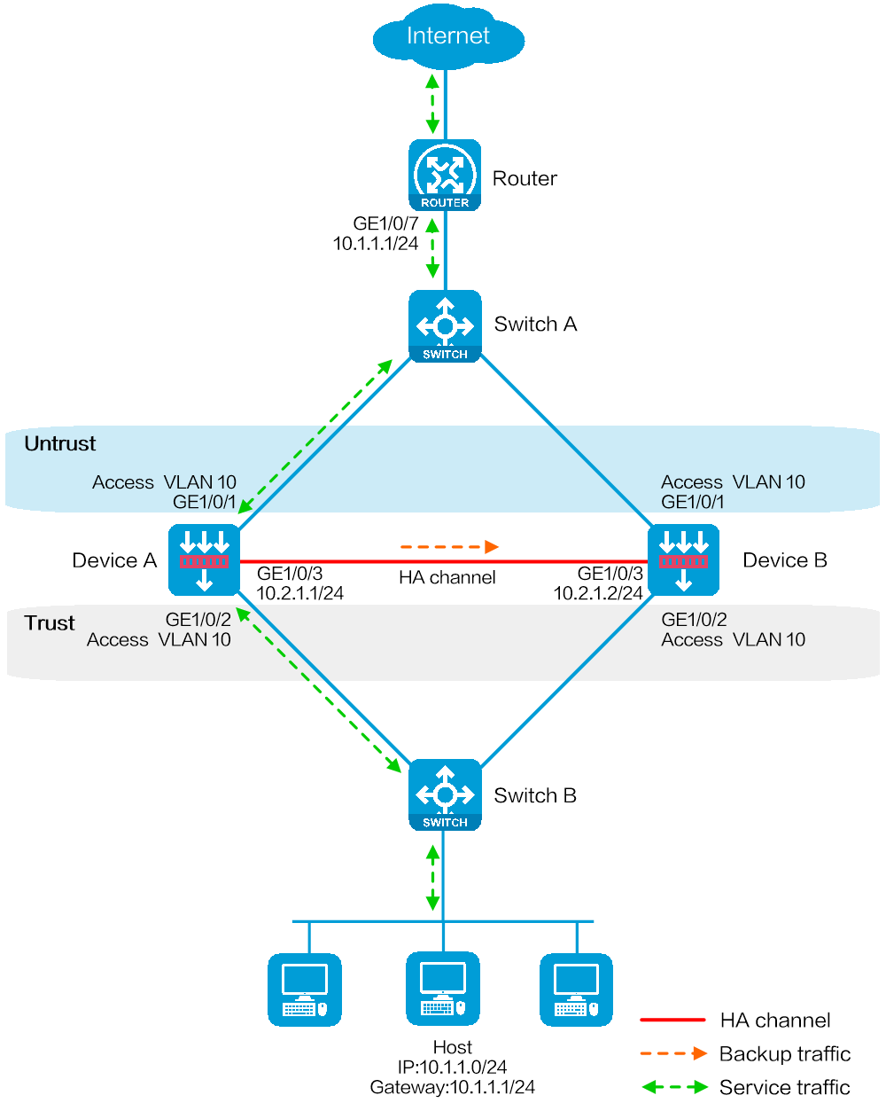
As shown in Figure 25, set up a transparent in-path hot backup system at the border between the Internet and the internal network of an enterprise to ensure service continuity.
· Configure the hot backup system to operate in active/standby mode.
· Connect Switch A and Switch B to Layer 2 interfaces of the hot backup system.
· Configure Device A and Device B as the primary device and the secondary device, respectively.
Software versions used
This configuration example was created and verified on E8371 of the F5000-AI160 device.
This configuration example was created and verified on E9671 of the M9000-X06 device.
Procedure
Configuring Switch A
# Create VLAN 10.
# Configure the interfaces attached to the hot backup system and the router to operate at Layer 2. Assign them to VLAN 10 as access interfaces.
Configuring Switch B
# Create VLAN 10.
# Configure the interfaces attached to the hot backup system and the host to operate at Layer 2. Assign them to VLAN 10 as access interfaces.
Configuring Device A
Configuring basic network settings
1. Configure Layer 2 service interfaces:
# On the top navigation bar, click Network.
# From the navigation pane, select Link > VLANs.
# Click Create.
a. Enter VLAN ID 10.
b. Click OK.
# On the top navigation bar, click Network.
# From the navigation pane, select Interface Configuration > Interfaces.
# Click the Edit icon for GE 1/0/1.
# In the dialog box that opens, configure the interface:
c. Select the Layer 2 link mode.
d. Select security zone Untrust.
e. Select VLAN 10.
f. On the VLAN tab, set the link type to Access and enter PVID 10.
g. Use the default settings for other parameters.
h. Click OK.
# Click the Edit icon for GE 1/0/2.
# In the dialog box that opens, configure the interface:
i. Select the Layer 2 link mode.
j. Select security zone Trust.
k. Select VLAN 10.
l. On the VLAN tab, set the link type to Access and enter PVID 10.
m. Use the default settings for other parameters.
n. Click OK.
2. Assign IP addresses to interfaces:
# On the top navigation bar, click Network.
# From the navigation pane, select Interface Configuration > Interfaces.
# Click the Edit icon for GE 1/0/3.
# In the dialog box that opens, configure the interface:
a. On the IPv4 Address tab, enter the IP address and mask of the interface. In this example, enter 10.2.1.1/24.
b. Use the default settings for other parameters.
c. Click OK.
3. Configure a security policy to permit service traffic:
Perform this task only on the primary device. The secondary device will synchronize security policy configuration with the primary device after the hot backup system is set up.
# On the top navigation bar, click Policies.
# From the navigation pane, select Security Policies > Security Policies.
# Select Create > Create a policy.
# In the dialog box that opens, configure a security policy to permit traffic from zone Trust to zone Untrust:
a. Enter security policy name Trust-Untrust.
b. Select source zone Trust.
c. Select destination zone Untrust.
d. Select IP version IPv4.
e. Set the action to Permit.
f. Enter source IP address 10.1.1.0/24.
g. Use the default settings for other parameters.
h. Click OK.
Configuring hot backup settings
# On the top navigation bar, click System.
# From the navigation pane, select High Availability > Hot Backup.
# Click Configure.
# Configure the hot backup parameters as shown in Figure 26.
Figure 26 Configuring hot backup parameters


# Click OK.
Configuring security services
# Configure security devices on the hot backup member devices. If the hot backup system can back up configuration for a module, configure the module only on the primary device (Device A).
Configuring Device B
Configuring basic network settings
1. Configure Layer 2 service interfaces:
# On the top navigation bar, click Network.
# From the navigation pane, select Link > VLANs.
# Click Create.
a. Enter VLAN ID 10.
b. Click OK.
# On the top navigation bar, click Network.
# From the navigation pane, select Interface Configuration > Interfaces.
# Click the Edit icon for GE 1/0/1.
# In the dialog box that opens, configure the interface:
c. Select the Layer 2 link mode.
d. Select security zone Untrust.
e. Select VLAN 10.
f. On the VLAN tab, set the link type to Access and enter PVID 10.
g. Use the default settings for other parameters.
h. Click OK.
# Click the Edit icon for GE 1/0/2.
# In the dialog box that opens, configure the interface:
i. Select the Layer 2 link mode.
j. Select security zone Trust.
k. Select VLAN 10.
l. On the VLAN tab, set the link type to Access and enter PVID 10.
m. Use the default settings for other parameters.
n. Click OK.
2. Assign IP addresses to interfaces:
# On the top navigation bar, click Network.
# From the navigation pane, select Interface Configuration > Interfaces.
# Click the Edit icon for GE 1/0/3.
# In the dialog box that opens, configure the interface:
a. On the IPv4 Address tab, enter the IP address and mask of the interface. In this example, enter 10.2.1.2/24.
b. Use the default settings for other parameters.
c. Click OK.
Configuring hot backup settings
# On the top navigation bar, click System.
# From the navigation pane, select High Availability > Hot Backup.
# Click Configure.
# Configure the hot backup parameters as shown in Figure 27.
Figure 27 Configuring hot backup parameters


# Click OK.
Configuring the host
# On the host, specify 10.1.1.1 as the default gateway.
Verifying the configuration
# Enable logging for the interzone policy that permits communication between security zones Trust and Untrust. Verity that only Device A generates log messages when the host communicates with the Internet.
Network configuration
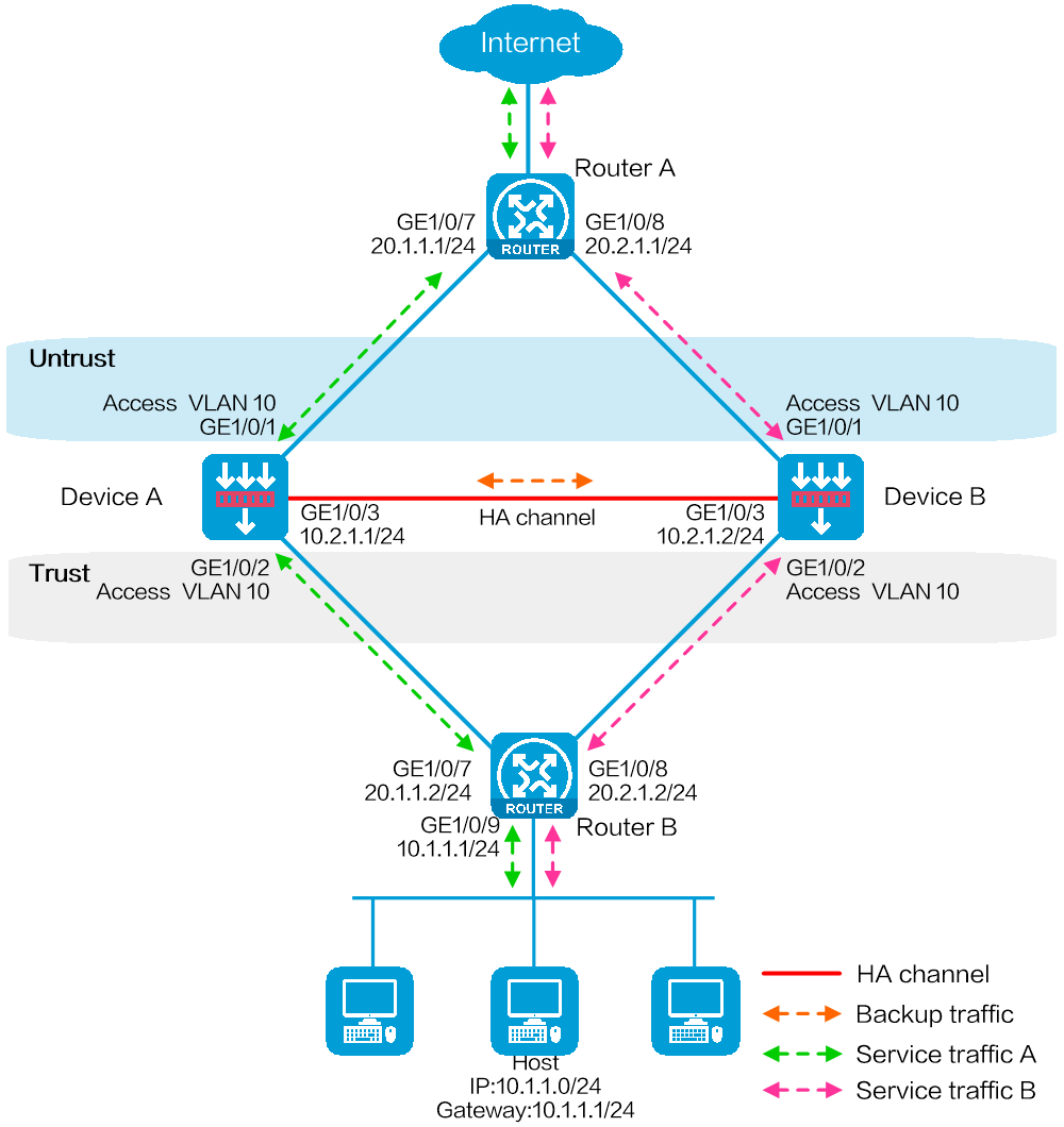
As shown in Figure 28, set up a transparent in-path hot backup system at the border between the Internet and the internal network of an enterprise to ensure service continuity.
· Configure the hot backup system to operate in dual-active mode.
· Connect Router A and Router B to Layer 2 interfaces of the hot backup system.
· Configure Device A and Device B to load share traffic.
Software versions used
This configuration example was created and verified on E8371 of the F5000-AI160 device.
This configuration example was created and verified on E9671 of the M9000-X06 device.
Procedure
Configuring Router A
# Configure OSPF for the hosts to access the Internet and for Device A and Device B to load share the traffic sent to the hosts.
Configuring Router B
# Configure OSPF for the hosts to access the Internet and for Device A and Device B to load share the traffic sent to the hosts.
Configuring Device A
Configuring basic network settings
1. Configure Layer 2 service interfaces:
# On the top navigation bar, click Network.
# From the navigation pane, select Link > VLANs.
# Click Create.
a. Enter VLAN ID 10.
b. Click OK.
# On the top navigation bar, click Network.
# From the navigation pane, select Interface Configuration > Interfaces.
# Click the Edit icon for GE 1/0/1.
# In the dialog box that opens, configure the interface:
c. Select the Layer 2 link mode.
d. Select security zone Untrust.
e. Select VLAN 10.
f. On the VLAN tab, set the link type to Access and enter PVID 10.
g. Use the default settings for other parameters.
h. Click OK.
# Click the Edit icon for GE 1/0/2.
# In the dialog box that opens, configure the interface:
i. Select the Layer 2 link mode.
j. Select security zone Trust.
k. Select VLAN 10.
l. On the VLAN tab, set the link type to Access and enter PVID 10.
m. Use the default settings for other parameters.
n. Click OK.
2. Assign IP addresses to interfaces:
# On the top navigation bar, click Network.
# From the navigation pane, select Interface Configuration > Interfaces.
# Click the Edit icon for GE 1/0/3.
# In the dialog box that opens, configure the interface:
a. On the IPv4 Address tab, enter the IP address and mask of the interface. In this example, enter 10.2.1.1/24.
b. Use the default settings for other parameters.
c. Click OK.
3. Configure a security policy to permit service traffic:
Perform this task only on the primary device. The secondary device will synchronize security policy configuration with the primary device after the hot backup system is set up.
# On the top navigation bar, click Policies.
# From the navigation pane, select Security Policies > Security Policies.
# Select Create > Create a policy.
# In the dialog box that opens, configure a security policy to permit traffic from zone Trust to zone Untrust:
a. Enter security policy name Trust-Untrust.
b. Select source zone Trust.
c. Select destination zone Untrust.
d. Select IP version IPv4.
e. Set the action to Permit.
f. Enter source IP address 10.1.1.0/24.
g. Use the default settings for other parameters.
h. Click OK.
4. Configure security policies to permit OSPF protocol packets:
Perform this task only on the primary device. The secondary device will synchronize security policy configuration with the primary device after the hot backup system is set up.
# On the top navigation bar, click Policies.
# From the navigation pane, select Security Policies > Security Policies.
# Select Create > Create a policy.
# In the dialog box that opens, configure a security policy to permit traffic from zone Trust to zone Untrust:
a. Enter security policy name ospf1.
b. Select source zone Untrust.
c. Select destination zone Local.
d. Select IP version IPv4.
e. Set the action to Permit.
f. Select policy group ospf.
g. Use the default settings for other parameters.
h. Click OK.
# Configure a security policy to permit traffic from zone Untrust to zone Trust:
i. Enter security policy name ospf2.
j. Select source zone Untrust.
k. Select destination zone Trust.
l. Select IP version IPv4.
m. Set the action to Permit.
n. Select policy group ospf.
o. Use the default settings for other parameters.
p. Click OK.
Configuring hot backup settings
# On the top navigation bar, click System.
# From the navigation pane, select High Availability > Hot Backup.
# Click Configure.
# Configure the hot backup parameters as shown in Figure 29.
Figure 29 Configuring hot backup parameters


# Click OK.
Configuring security services
# Configure security devices on the hot backup member devices. If the hot backup system can back up configuration for a module, configure the module only on the primary device (Device A).
Configuring Device B
Configuring basic network settings
1. Configure Layer 2 service interfaces:
# On the top navigation bar, click Network.
# From the navigation pane, select Link > VLANs.
# Click Create.
a. Enter VLAN ID 10.
b. Click OK.
# On the top navigation bar, click Network.
# From the navigation pane, select Interface Configuration > Interfaces.
# Click the Edit icon for GE 1/0/1.
# In the dialog box that opens, configure the interface:
c. Select the Layer 2 link mode.
d. Select security zone Untrust.
e. Select VLAN 10.
f. On the VLAN tab, set the link type to Access and enter PVID 10.
g. Use the default settings for other parameters.
h. Click OK.
# Click the Edit icon for GE 1/0/2.
# In the dialog box that opens, configure the interface:
i. Select the Layer 2 link mode.
j. Select security zone Trust.
k. Select VLAN 10.
l. On the VLAN tab, set the link type to Access and enter PVID 10.
m. Use the default settings for other parameters.
n. Click OK.
2. Assign IP addresses to interfaces:
# On the top navigation bar, click Network.
# From the navigation pane, select Interface Configuration > Interfaces.
# Click the Edit icon for GE 1/0/3.
# In the dialog box that opens, configure the interface:
a. On the IPv4 Address tab, enter the IP address and mask of the interface. In this example, enter 10.2.1.2/24.
b. Use the default settings for other parameters.
c. Click OK.
Configuring hot backup settings
# On the top navigation bar, click System.
# From the navigation pane, select High Availability > Hot Backup.
# Click Configure.
# Configure the hot backup parameters as shown in Figure 30.
Figure 30 Configuring hot backup parameters


# Click OK.
Configuring the hosts
# On the hosts, specify 10.1.1.1 as the default gateway.
Verifying the configuration
# Enable logging for the interzone policy that permits communication between security zones Trust and Untrust. Verity that both Device A and Device B generate log messages when the hosts communicate with the Internet.
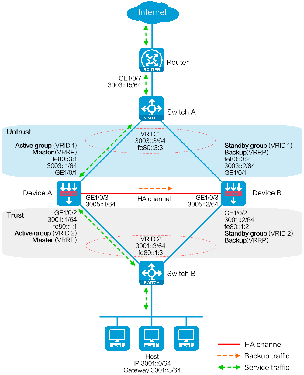
Network configuration
As shown in Figure 31, set up a hot backup system at the border between the Internet and the internal network of an enterprise to ensure service continuity.
· Configure the hot backup system to collaborate with VRRP.
· Configure the hot backup system to operate in active/standby mode.
· Configure Device A and Device B as the primary device and the secondary device, respectively.
Software versions used
This configuration example was created and verified on E8371 of the F5000-AI160 device.
This configuration example was created and verified on E9671 of the M9000-X06 device.
Procedure
Configuring Switch A
# Create VLAN 10.
# Configure the interfaces attached to the hot backup system and the router to operate at Layer 2. Assign them to VLAN 10 as access interfaces.
Configuring Switch B
# Create VLAN 10.
# Configure the interfaces attached to the hot backup system and the host to operate at Layer 2. Assign them to VLAN 10 as access interfaces.
Configuring the router
# Assign 3003::15/64 to GigabitEthernet 1/0/7.
# Configure routes as follows:
· Specify 3003::3/64 (virtual IP address of VRRP group 1) as the next hop of the routes to the internal network.
· Specify the IP address of the peer interface attached to the traffic outgoing interface as the next hop of the route to the Internet.
Configuring Device A
Configuring basic network settings
1. Assign IP addresses to interfaces:
# On the top navigation bar, click Network.
# From the navigation pane, select Interface Configuration > Interfaces.
# Click the Edit icon for GE 1/0/1.
# In the dialog box that opens, configure the interface:
a. On the Basic Configuration tab, select the Untrust security zone.
b. On the IPv6 Address tab, enter global unicast address 3003::1/64 and link local address fe80::3:1.
c. Use the default settings for other parameters.
d. Click OK.
# Click the Edit icon for GE 1/0/2.
# In the dialog box that opens, configure the interface:
e. On the Basic Configuration tab, select the Trust security zone.
f. On the IPv6 Address tab, enter global unicast address 3001::1/64 and link local address fe80::1:1.
g. Use the default settings for other parameters.
h. Click OK.
# Click the Edit icon for GE 1/0/3.
# In the dialog box that opens, configure the interface:
i. On the IPv6 Address tab, enter global unicast address 3005::1/64 and configure the interface to use a link local address generated automatically.
j. Use the default settings for other parameters.
k. Click OK.
2. Configure routing:
This step uses static routing as an example. To use dynamic routing, configure a dynamic routing protocol.
# On the top navigation bar, click Network.
# From the navigation pane, select Routing > Static Routing.
# On the IPv6 Static Routing tab, click Create.
# In the dialog box that opens, configure an IPv6 static route:
a. Enter destination IP address 0::0.
b. Enter mask length 0.
c. Enter next hop address 3003::15.
d. Use the default settings for other parameters.
e. Click OK.
3. Configure a security policy to permit service traffic:
Perform this task only on the primary device. The secondary device will synchronize security policy configuration with the primary device after the hot backup system is set up.
# On the top navigation bar, click Policies.
# From the navigation pane, select Security Policies > Security Policies.
# Select Create > Create a policy.
# In the dialog box that opens, configure a security policy to permit traffic from zone Trust to zone Untrust:
a. Enter security policy name Trust-Untrust.
b. Select source zone Trust.
c. Select destination zone Untrust.
d. Select IP version IPv6.
e. Set the action to Permit.
f. Enter source IP address 3001::0/64.
g. Use the default settings for other parameters.
h. Click OK.
4. Configure security policies to permit VRRP protocol packets:
This task allows Device A and Device B to exchange VRRP packets and elect a VRRP master when the RBM channels are disconnected.
Perform this task only on the primary device. The secondary device will synchronize security policy configuration with the primary device after the hot backup system is set up.
# On the top navigation bar, click Policies.
# From the navigation pane, select Security Policies > Security Policies.
# Select Create > Create a policy.
# In the dialog box that opens, configure a security policy to permit traffic from zone Trust to zone Local:
a. Enter security policy name vrrp1.
b. Select source zone Trust.
c. Select destination zone Local.
d. Select IP version IPv6.
e. Set the action to Permit.
f. Select policy group vrrp.
g. Use the default settings for other parameters.
h. Click OK.
# Configure a security policy to permit traffic from zone Local to zone Trust:
i. Enter security policy name vrrp2.
j. Select source zone Local.
k. Select destination zone Trust.
l. Select IP version IPv6.
m. Set the action to Permit.
n. Select policy group vrrp.
o. Use the default settings for other parameters.
p. Click OK.
# Configure a security policy to permit traffic from zone Untrust to zone Local:
q. Enter security policy name vrrp3.
r. Select source zone Untrust.
s. Select destination zone Local.
t. Select IP version IPv6.
u. Set the action to Permit.
v. Select policy group vrrp.
w. Use the default settings for other parameters.
x. Click OK.
# Configure a security policy to permit traffic from zone Local to zone Untrust:
y. Enter security policy name vrrp4.
z. Select source zone Local.
aa. Select destination zone Untrust.
bb. Select IP version IPv6.
cc. Set the action to Permit.
dd. Select policy group vrrp.
ee. Use the default settings for other parameters.
ff. Click OK.
Configuring hot backup settings
# On the top navigation bar, click System.
# From the navigation pane, select High Availability > Hot Backup.
# Click Configure.
# Configure the hot backup parameters as shown in Figure 32.
Figure 32 Configuring hot backup parameters
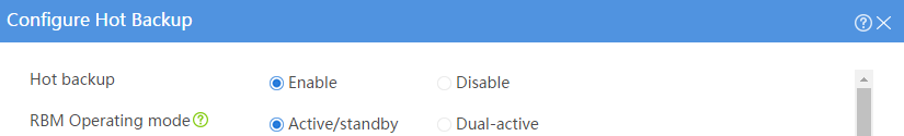


# Click OK.
Associating the hot backup system with VRRP
# On the top navigation bar, click System.
# From the navigation pane, select High Availability > VRRP.
# Click Create.
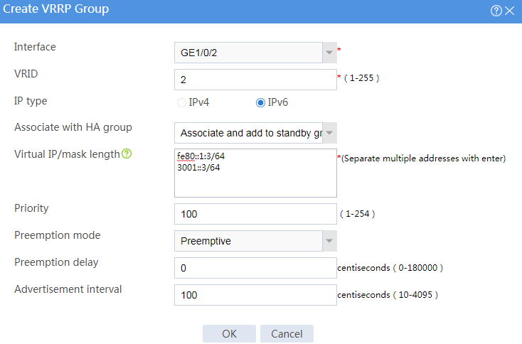
# Configure VRRP groups as shown in the follow figures.
Figure 33 Creating VRRP group 1

Figure 34 Creating VRRP group 2
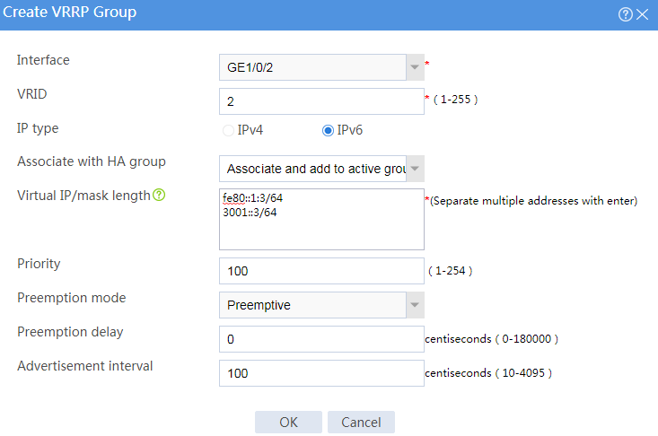
# Click OK.
Configuring security services
# Configure security devices on the hot backup member devices. If the hot backup system can back up configuration for a module, configure the module only on the primary device (Device A).
Configuring Device B
Configuring basic network settings
1. Assign IP addresses to interfaces:
# On the top navigation bar, click Network.
# From the navigation pane, select Interface Configuration > Interfaces.
# Click the Edit icon for GE 1/0/1.
# In the dialog box that opens, configure the interface:
a. On the Basic Configuration tab, select the Untrust security zone.
b. On the IPv6 Address tab, enter global unicast address 3003::2/64 and link local address fe80::3:2.
c. Use the default settings for other parameters.
d. Click OK.
# Click the Edit icon for GE 1/0/2.
# In the dialog box that opens, configure the interface:
e. On the Basic Configuration tab, select the Trust security zone.
f. On the IPv6 Address tab, enter global unicast address 3001::2/64 and link local address fe80::1:2.
g. Use the default settings for other parameters.
h. Click OK.
# Click the Edit icon for GE 1/0/3.
# In the dialog box that opens, configure the interface:
i. On the IPv6 Address tab, enter global unicast address 3005::2/64 and configure the interface to use a link local address generated automatically.
j. Use the default settings for other parameters.
k. Click OK.
2. Configure routing:
This step uses static routing as an example. To use dynamic routing, configure a dynamic routing protocol.
# On the top navigation bar, click Network.
# From the navigation pane, select Routing > Static Routing.
# On the IPv6 Static Routing tab, click Create.
# In the dialog box that opens, configure an IPv6 static route:
a. Enter destination IP address 0::0.
b. Enter mask length 0.
c. Enter next hop address 3003::15.
d. Use the default settings for other parameters.
e. Click OK.
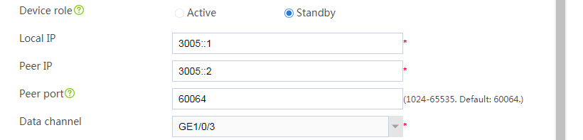
Configuring hot backup settings
# On the top navigation bar, click System.
# From the navigation pane, select High Availability > Hot Backup.
# Click Configure.
# Configure the hot backup parameters as shown in Figure 35.
Figure 35 Configuring hot backup parameters

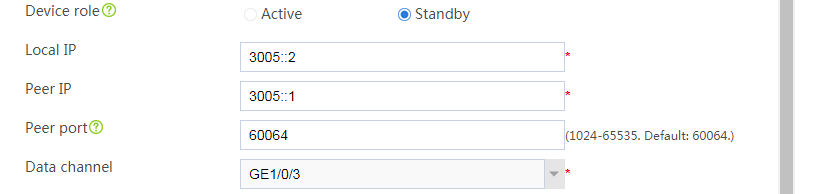
# Click OK.
Associating the hot backup system with VRRP
# On the top navigation bar, click System.
# From the navigation pane, select High Availability > VRRP.
# Click Create.
# Configure VRRP groups as shown in the follow figures.
Figure 36 Creating VRRP group 1
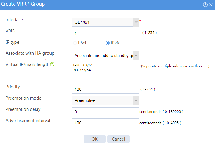
Figure 37 Creating VRRP group 2
# Click OK.
Configuring the host
# On the host, specify 3001::3 (virtual IP address of VRRP group 2) as the default gateway.
Verifying the configuration
# Enable logging for the interzone policy that permits communication between security zones Trust and Untrust. Verity that only Device A generates log messages when the host communicates with the Internet.
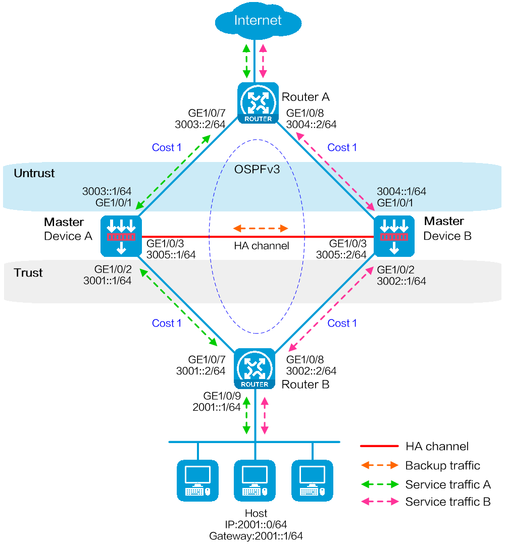
Network configuration
As shown in Figure 38, set up a hot backup system at the border between the Internet and the internal network of an enterprise to ensure service continuity.
· Configure the hot backup system to collaborate with OSPFv3.
· Configure the hot backup system to operate in dual-active mode.
· Configure Device A and Device B to load share traffic.
Software versions used
This configuration example was created and verified on E8371 of the F5000-AI160 device.
This configuration example was created and verified on E9671 of the M9000-X06 device.
Procedure
Configuring Router A
# Assign 3003::2/64 to GigabitEthernet 1/0/7.
# Assign 3004::2/64 to GigabitEthernet 1/0/8.
# Configure OSPFv3 for Router A to have Layer 3 reachability to other devices.
# Configure per-flow load sharing for IP forwarding.
Configuring Router B
# Assign 3001::2/64 to GigabitEthernet 1/0/7.
# Assign 3002::2/64 to GigabitEthernet 1/0/8.
# Configure OSPFv3 for Router B to have Layer 3 reachability to other devices.
# Configure per-flow load sharing for IP forwarding.
Configuring Device A
Configuring basic network settings
1. Assign IP addresses to interfaces:
# On the top navigation bar, click Network.
# From the navigation pane, select Interface Configuration > Interfaces.
# Click the Edit icon for GE 1/0/1.
# In the dialog box that opens, configure the interface:
a. On the Basic Configuration tab, select the Untrust security zone.
b. On the IPv6 Address tab, enter global unicast address 3003::1/64 and configure the interface to use a link local address generated automatically.
c. Use the default settings for other parameters.
d. Click OK.
# Click the Edit icon for GE 1/0/2.
# In the dialog box that opens, configure the interface:
e. On the Basic Configuration tab, select the Trust security zone.
f. On the IPv6 Address tab, enter global unicast address 3001::1/64 and configure the interface to use a link local address generated automatically.
g. Use the default settings for other parameters.
h. Click OK.
# Click the Edit icon for GE 1/0/3.
# In the dialog box that opens, configure the interface:
i. On the IPv6 Address tab, enter global unicast address 3005::1/64 and configure the interface to use a link local address generated automatically.
j. Use the default settings for other parameters.
k. Click OK.
2. Configure routing:
This step uses OSPF as an example. You can configure another dynamic routing protocol as needed.
# On the top navigation bar, click Network.
# From the navigation pane, select Routing > OSPF.
# Click Create.
# In the dialog box that opens, configure an OSPF instance:
a. Select version OSPFv3.
b. Enter instance name 1.
c. Enter router ID 2.1.1.1.
d. Use the default settings for other parameters.
e. Click OK.
# Click 0 in the Number of OSPF areas column for the created OSPF instance.
# On the OSPF area configuration page that opens, click Create.
# In the dialog box that opens, configure an area:
f. Enter area ID 0.0.0.0.
g. Click OK.
# Click 0 in the Number of OSPF interfaces column for the created OSPF instance.
# On the OSPF interface configuration page that opens, click Create.
# In the dialog box that opens, configure an area:
h. Enter area ID 0.0.0.0.
i. Select interface GE 1/0/1.
j. Enter interface instance ID 1.
k. Click OK.
# Click 1 in the Number of OSPF interfaces column for the created OSPF instance.
# On the OSPF interface configuration page that opens, click Create.
# In the dialog box that opens, configure an area:
l. Enter area ID 0.0.0.0.
m. Select interface GE 1/0/2.
n. Enter interface instance ID 1.
o. Click OK.
3. Configure a security policy to permit service traffic:
Perform this task only on the primary device. The secondary device will synchronize security policy configuration with the primary device after the hot backup system is set up.
# On the top navigation bar, click Policies.
# From the navigation pane, select Security Policies > Security Policies.
# Select Create > Create a policy.
# In the dialog box that opens, configure a security policy to permit traffic from zone Trust to zone Untrust:
a. Enter security policy name Trust-Untrust.
b. Select source zone Trust.
c. Select destination zone Untrust.
d. Select IP version IPv6.
e. Set the action to Permit.
f. Enter source IP address 2001::0/64.
g. Use the default settings for other parameters.
h. Click OK.
4. Configure security policies to permit OSPF protocol packets:
Perform this task only on the primary device. The secondary device will synchronize security policy configuration with the primary device after the hot backup system is set up.
# On the top navigation bar, click Policies.
# From the navigation pane, select Security Policies > Security Policies.
# Select Create > Create a policy.
# In the dialog box that opens, configure a security policy to permit traffic from zone Trust to zone Local:
a. Enter security policy name ospf1.
b. Select source zone Trust.
c. Select destination zone Local.
d. Select IP version IPv6.
e. Set the action to Permit.
f. Select policy group ospf.
g. Use the default settings for other parameters.
h. Click OK.
# Configure a security policy to permit traffic from zone Local to zone Trust:
i. Enter security policy name ospf2.
j. Select source zone Local.
k. Select destination zone Trust.
l. Select IP version IPv6.
m. Set the action to Permit.
n. Select policy group ospf.
o. Use the default settings for other parameters.
p. Click OK.
# Configure a security policy to permit traffic from zone Untrust to zone Local:
q. Enter security policy name ospf3.
r. Select source zone Untrust.
s. Select destination zone Local.
t. Select IP version IPv6.
u. Set the action to Permit.
v. Select policy group ospf.
w. Use the default settings for other parameters.
x. Click OK.
# Configure a security policy to permit traffic from zone Local to zone Untrust:
y. Enter security policy name ospf4.
z. Select source zone Local.
aa. Select destination zone Untrust.
bb. Select IP version IPv6.
cc. Set the action to Permit.
dd. Select policy group ospf.
ee. Use the default settings for other parameters.
ff. Click OK.
Configuring hot backup settings
# On the top navigation bar, click System.
# From the navigation pane, select High Availability > Track.
# Click Add.
# Configure a track entry:
1. Enter track entry ID 1.
2. Select the interface module.
3. Select GE 1/0/1 as the monitored interface.
4. Use the default settings for other parameters.
# Configure track entry 2 to monitor the state of GE 1/0/2. (Details not shown.)
# On the top navigation bar, click System.
# From the navigation pane, select High Availability > Hot Backup.
# Click Configure.
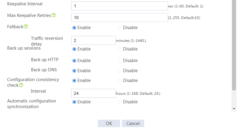
# Configure the hot backup parameters as shown in Figure 39.
Figure 39 Configuring hot backup parameters


# Click OK.
Configuring security services
# Configure security devices on the hot backup member devices. If the hot backup system can back up configuration for a module, configure the module only on the primary device (Device A).
Configuring Device B
Configuring basic network settings
1. Assign IP addresses to interfaces:
# On the top navigation bar, click Network.
# From the navigation pane, select Interface Configuration > Interfaces.
# Click the Edit icon for GE 1/0/1.
# In the dialog box that opens, configure the interface:
a. On the Basic Configuration tab, select the Untrust security zone.
b. On the IPv6 Address tab, enter global unicast address 3004::1/64 and configure the interface to use a link local address generated automatically.
c. Use the default settings for other parameters.
d. Click OK.
# Click the Edit icon for GE 1/0/2.
# In the dialog box that opens, configure the interface:
e. On the Basic Configuration tab, select the Trust security zone.
f. On the IPv6 Address tab, enter global unicast address 3002::1/64 and configure the interface to use a link local address generated automatically.
g. Use the default settings for other parameters.
h. Click OK.
# Click the Edit icon for GE 1/0/3.
# In the dialog box that opens, configure the interface:
i. On the IPv6 Address tab, enter global unicast address 3005::2/64 and configure the interface to use a link local address generated automatically.
j. Use the default settings for other parameters.
k. Click OK.
2. Configure routing:
This step uses OSPF as an example. You can configure another dynamic routing protocol as needed.
# On the top navigation bar, click Network.
# From the navigation pane, select Routing > OSPF.
# Click Create.
# In the dialog box that opens, configure an OSPF instance:
a. Select version OSPFv3.
b. Enter instance name 1.
c. Enter router ID 2.1.10.1.
d. Use the default settings for other parameters.
e. Click OK.
# Click 0 in the Number of OSPF areas column for the created OSPF instance.
# On the OSPF area configuration page that opens, click Create.
# In the dialog box that opens, configure an area:
f. Enter area ID 0.0.0.0.
g. Click OK.
# Click 0 in the Number of OSPF interfaces column for the created OSPF instance.
# On the OSPF interface configuration page that opens, click Create.
# In the dialog box that opens, configure an area:
h. Enter area ID 0.0.0.0.
i. Select interface GE 1/0/1.
j. Enter interface instance ID 1.
k. Click OK.
# Click 1 in the Number of OSPF interfaces column for the created OSPF instance.
# On the OSPF interface configuration page that opens, click Create.
# In the dialog box that opens, configure an area:
l. Enter area ID 0.0.0.0.
m. Select interface GE 1/0/2.
n. Enter interface instance ID 1.
o. Click OK.
Configuring hot backup settings
# On the top navigation bar, click System.
# From the navigation pane, select High Availability > Track.
# Click Add.
# Configure a track entry:
1. Enter track entry ID 1.
2. Select the interface module.
3. Select GE 1/0/1 as the monitored interface.
4. Use the default settings for other parameters.
# Configure track entry 2 to monitor the state of GE 1/0/2. (Details not shown.)
# On the top navigation bar, click System.
# From the navigation pane, select High Availability > Hot Backup.
# Click Configure.
# Configure the hot backup parameters as shown in Figure 40.
Figure 40 Configuring hot backup parameters
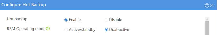
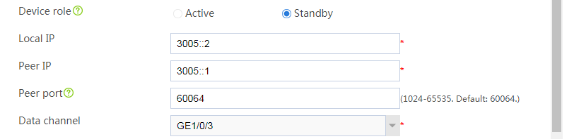

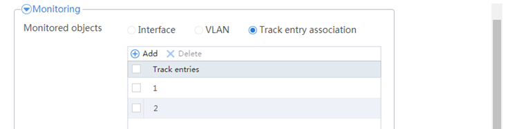
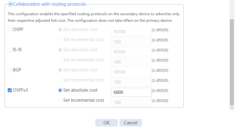
# Click OK.
Configuring the hosts
# On the hosts, specify 2002::1 as the default gateway.
Verifying the configuration
# Enable logging for the interzone policy that permits communication between security zones Trust and Untrust. Verity that both Device A and Device B generate log messages when the hosts communicate with the Internet.
