- Table of Contents
-
- H3C SecPath M9000 Multi Service Security Gateway Configuration Examples(V7)(E9X71)-6W700
- 00-Preface
- 01-About the configuration examples
- 02-Web Login Configuration Examples
- 03-Internet Access Through a Static IP Address Configuration Examples
- 04-Internet access through PPPoE configuration examples
- 05-License Configuration Examples
- 06-Signature Library Upgrade Configuration Examples
- 07-Software Upgrade Examples
- 08-Routing deployment configuration examples
- 09-Transparent deployment configuration examples
- 10-Static routing configuration examples
- 11-RIP configuration examples
- 12-OSPF configuration examples
- 13-BGP configuration examples
- 14-Policy-based routing configuration examples
- 15-Security Policy Configuration Examples
- 16-APR-Based Security Policy Configuration Examples
- 17-Object Group Configuration Examples
- 18-User identification configuration examples
- 19-Attack defense configuration examples
- 20-Request Limit Configuration Examples
- 21-IPS Configuration Examples
- 22-URL Filtering Configuration Examples
- 23-Anti-Virus Configuration Examples
- 24-File Filtering Configuration Examples
- 25-Data Filtering Configuration Examples
- 26-WAF Configuration Examples
- 27-IP Reputation Configuration Examples
- 28-APT Defense Configuration Examples
- 29-NetShare Control Configuration Examples
- 30-Bandwidth Management Configuration Examples
- 31-IPsec configuration examples
- 32-SSL VPN IP access configuration examples
- 32-SSL VPN TCP access configuration examples
- 32-SSL VPN Web access configuration examples
- 33-L2TP Configuration Examples
- 34-NAT configuration examples
- 35-NPTv6 Configuration Examples
- 36-Policy-based NAT configuration examples
- 37-NAT hairpin configuration examples
- 38-NAT Flow Logging Configuration Examples
- 39-Inbound Link Load Balancing Configuration Examples
- 40-Outbound Link Load Balancing Configuration Examples
- 41-Server Load Balancing Configuration Examples
- 42-Transparent DNS Proxy Configuration Examples
- 43-Hot Backup Configuration Examples
- 44-Context Configuration Examples
- 45-DNS configuration examples
- 46-Server Connection Detection Configuration Examples
- 47-Connection Limit Configuration Examples
- 48-Public key management configuration examples
- 49-SSL Decryption Configuration Examples
- 50-MAC Address Learning Through a Layer 3 Device Configuration Examples
- 51-4G Configuration Examples
- 52-WLAN Configuration Examples
- Related Documents
-
| Title | Size | Download |
|---|---|---|
| 47-Connection Limit Configuration Examples | 146.25 KB |
Connection limit configuration examples
Contents
· Example: Configuring connection limits
The following information provides connection limit configuration examples.
This document is not restricted to specific software or hardware versions. Procedures and information in the examples might be slightly different depending on the software or hardware version of the device.
The configuration examples were created and verified in a lab environment, and all the devices were started with the factory default configuration. When you are working on a live network, make sure you understand the potential impact of every command on your network.
The following information is provided based on the assumption that you have basic knowledge of the connection limit feature.
Network configuration
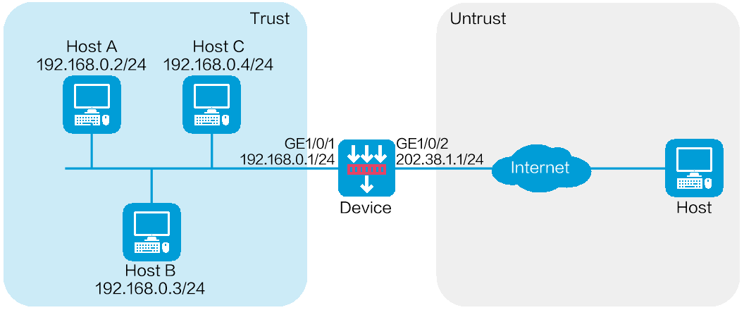
As shown in Figure 1, a firewall is deployed as the egress device that connects the internal network to the Internet.
Configure connection limits to meet the following requirements:
· All hosts on 192.168.0.0/24 can establish a total of up to 100000 connections with the Internet.
· Each host on 192.168.0.0/24 can establish a maximum of 100 connections with the Internet.
Software versions used
This configuration example was created and verified on E8371 of the F5000-AI160 device.
This configuration example was created and verified on E9671 of the M9000-X06 device.
Procedures
Configuring the device
1. Assign IP addresses to interfaces and add the interfaces to security zones.
# On the top navigation bar, click Network.
# From the navigation pane, select Interface Configuration > Interfaces.
# Click the Edit icon for GE 1/0/1.
# In the dialog box that opens, configure the interface:
¡ Select the Trust security zone.
¡ On the IPv4 Address tab, enter the IP address and mask of the interface. In this example, enter 192.168.0.1/24.
¡ Use the default settings for other parameters.
¡ Click OK.
# Add GE 1/0/2 to the Untrust security zone and set its IP address to 202.38.1.1/24 in the same way you configure GE 1/0/1.
2. Configure security policies.
# On the top navigation bar, click Policies.
# From the navigation pane, select Security Policies > Security Policies.
# Click Create.
# In the dialog box that opens, configure a security policy:
¡ Enter policy name test-a.
¡ Select source zone Trust.
¡ Select destination zone Untrust.
¡ Select type IPv4.
¡ Select action Permit.
¡ Enter source IPv4 address 192.168.0.0/24.
¡ Enter destination IPv4 address 202.38.1.0/24.
¡ Use the default settings for other parameters.
¡ Click OK.
3. Configure connection limit policies.
# On the top navigation bar, click Policies.
# From the navigation pane, select Attack Defense > Connection Limit.
# Click Create.
Figure 2 Creating connection limit policy 1
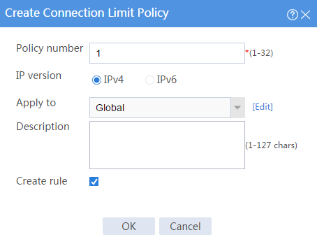
# In the dialog box that opens, configure connection limit policy 1:
¡ Enter policy number 1.
¡ Select IP version IPv4.
¡ Select Global for the Apply to field.
¡ Select Create rule.
¡ Click OK to create a connection limit rule.
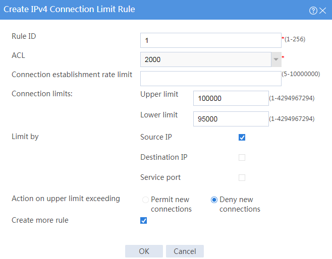
# In the dialog box that opens, configure connection limit rule 1:
¡ Enter rule ID 1.
¡ Select ACL 2000. This ACL matches the source IP addresses on the network segment 192.168.0.0/24..
¡ Set the upper limit to 100000 and lower limit to 95000.
¡ Select Source IP for the Limit by field.
¡ Deselect Create more rule.
¡ Click OK.
Figure 3 Creating connection limit rule 1
# Click Create to create another connection limit policy.
Figure 4 Creating connection limit policy 2
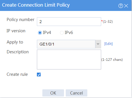
# In the dialog box that opens, configure connection limit policy 2:
¡ Enter policy number 2.
¡ Select IP version IPv4.
¡ Select GE1/0/1 for the Apply to field.
¡ Select Create rule.
¡ Click OK to create a connection limit rule.
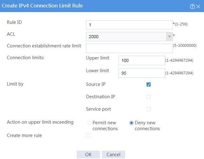
# In the dialog box that opens, configure connection limit rule 1:
¡ Enter rule ID 1.
¡ Select ACL 2000. This ACL matches the source IP addresses on the network segment 192.168.0.0/24.
¡ Set the upper limit to 100 and lower limit to 95.
¡ Select Source IP for the Limit by field.
¡ Deselect Create more rule.
¡ Click OK.
Figure 5 Creating connection limit rule 1
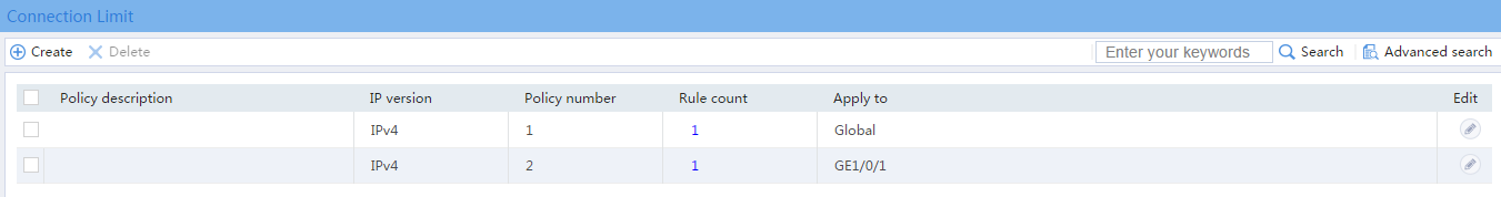
After the configuration, the connection limit policies appear as follows:
Verifying the configuration
# Verify that all hosts on 192.168.0.0/24 can establish a total of up to 100000 connections with the Internet and that each host on 192.168.0.0/24 can establish a maximum of 100 connections with the Internet.
