- Table of Contents
-
- H3C SecPath M9000 Multi Service Security Gateway Configuration Examples(V7)(E9X71)-6W700
- 00-Preface
- 01-About the configuration examples
- 02-Web Login Configuration Examples
- 03-Internet Access Through a Static IP Address Configuration Examples
- 04-Internet access through PPPoE configuration examples
- 05-License Configuration Examples
- 06-Signature Library Upgrade Configuration Examples
- 07-Software Upgrade Examples
- 08-Routing deployment configuration examples
- 09-Transparent deployment configuration examples
- 10-Static routing configuration examples
- 11-RIP configuration examples
- 12-OSPF configuration examples
- 13-BGP configuration examples
- 14-Policy-based routing configuration examples
- 15-Security Policy Configuration Examples
- 16-APR-Based Security Policy Configuration Examples
- 17-Object Group Configuration Examples
- 18-User identification configuration examples
- 19-Attack defense configuration examples
- 20-Request Limit Configuration Examples
- 21-IPS Configuration Examples
- 22-URL Filtering Configuration Examples
- 23-Anti-Virus Configuration Examples
- 24-File Filtering Configuration Examples
- 25-Data Filtering Configuration Examples
- 26-WAF Configuration Examples
- 27-IP Reputation Configuration Examples
- 28-APT Defense Configuration Examples
- 29-NetShare Control Configuration Examples
- 30-Bandwidth Management Configuration Examples
- 31-IPsec configuration examples
- 32-SSL VPN IP access configuration examples
- 32-SSL VPN TCP access configuration examples
- 32-SSL VPN Web access configuration examples
- 33-L2TP Configuration Examples
- 34-NAT configuration examples
- 35-NPTv6 Configuration Examples
- 36-Policy-based NAT configuration examples
- 37-NAT hairpin configuration examples
- 38-NAT Flow Logging Configuration Examples
- 39-Inbound Link Load Balancing Configuration Examples
- 40-Outbound Link Load Balancing Configuration Examples
- 41-Server Load Balancing Configuration Examples
- 42-Transparent DNS Proxy Configuration Examples
- 43-Hot Backup Configuration Examples
- 44-Context Configuration Examples
- 45-DNS configuration examples
- 46-Server Connection Detection Configuration Examples
- 47-Connection Limit Configuration Examples
- 48-Public key management configuration examples
- 49-SSL Decryption Configuration Examples
- 50-MAC Address Learning Through a Layer 3 Device Configuration Examples
- 51-4G Configuration Examples
- 52-WLAN Configuration Examples
- Related Documents
-
| Title | Size | Download |
|---|---|---|
| 14-Policy-based routing configuration examples | 236.81 KB |
Policy-based routing configuration examples
· Example: Configuring policy-based routing
This document provides policy-based routing configuration examples.
Policy-based routing (PBR) uses user-defined policies to route packets. A policy can specify parameters for packets that match specific criteria such as ACLs. The parameters include the next hop and output interface. PBR has higher forwarding priority than static routing and dynamic routing (for example, BGP) that forward packets according to routing table lookup.
This document is not restricted to specific software or hardware versions. Procedures and information in the examples might be slightly different depending on the software or hardware version of the device.
The configuration examples were created and verified in a lab environment, and all the devices were started with the factory default configuration. When you are working on a live network, make sure you understand the potential impact of every command on your network.
The following information is provided based on the assumption that you have basic knowledge of PBR.
Example: Configuring policy-based routing
Network configuration
As shown in Figure 1, an enterprise deploys a security gateway Device A that is connected to internal networks A (192.168.1.0/24) and B (192.168.2.0/24) and ISP links A and B. ISP link A is connected to access device C with access point IP address 1.1.1.2/30. ISP link B is connected to access device D with access point IP address 2.2.2.2/30. Configure PBR to meet the following requirements:
· Users in network A access the external network through ISP link A, and users in network B access the external network through ISP link B.
· When one of the ISP links fails, user traffic from the internal network can be forwarded through the other ISP link.

Software versions used
This configuration example was created and verified on E8371 of the F5000-AI160 device.
This configuration example was created and verified on E9671 of the M9000-X06 device.
Procedure
Configuring Device A
1. Assign IP addresses to interfaces and add the interfaces to security zones.
# On the top navigation bar, click Network.
# From the navigation pane, select Interface Configuration > Interfaces.
# Click the Edit icon for GE 1/0/1.
# In the dialog box that opens, configure the IP address and security zone settings:
a. Select the Trust security zone.
b. Enter the IP address and mask of the interface. In this example, enter 192.168.3.2/24.
c. Use default settings for other parameters.
# Configure the IP address and security zone settings for GE 1/0/2:
a. Select the Untrust security zone.
b. Enter the IP address and mask of the interface. In this example, enter 1.1.1.1/30.
c. Use default settings for other parameters.
# Configure the IP address and security zone settings for GE 1/0/3:
a. Select the Untrust security zone.
b. Enter the IP address and mask of the interface. In this example, enter 2.2.2.1/30.
c. Use default settings for other parameters.
# Click OK.
2. Configure static routes:
You can configure a dynamic routing protocol based on network requirements. This example uses static routes as an example.
# On the top navigation bar, click Network.
# From the navigation pane, select Routing > Static Routing.
# On the IPv4 Static Routing tab, click Create.
# In the dialog box that opens, configure the following parameters for the static route to access network A:
a. Enter the destination IP address 192.168.1.0.
b. Specify the mask length as 24.
c. Specify the next hop IP address as 192.168.3.1.
d. Use default settings for other parameters.
# Click OK.
# Configure the following parameters for the static route to access network B:
a. Enter the destination IP address 192.168.2.0.
b. Specify the mask length as 24.
c. Specify the next hop IP address as 192.168.3.1.
d. Use default settings for other parameters.
# Click OK.
3. Create a security policy.
# On the top navigation bar, click Policies.
# From the navigation pane, select Security Policies > Security Policies.
# Select Create > Create a policy.
# In the dialog box that opens, configure security policy secpolicy:
b. Specify the source zone as Trust.
c. Specify the destination zone as Untrust.
d. Select the IPv4 type.
e. Specify the action as Permit.
f. Specify source IPv4 addresses 192.168.1.0/24 and 192.168.2.0/24.
g. Use default settings for other parameters.
# Click OK.
4. Create ACLs.
# On the top navigation bar, click Objects.
# From the navigation pane, select ACL > IPv4.
# Select Create to create an ACL to match user traffic from network A to the external network, as shown in Figure 2.
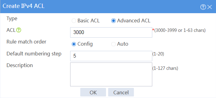
# Click OK, and then add ACL rules, as shown in Figure 3 and Figure 4.
Figure 3 Adding rules to ACL 3000
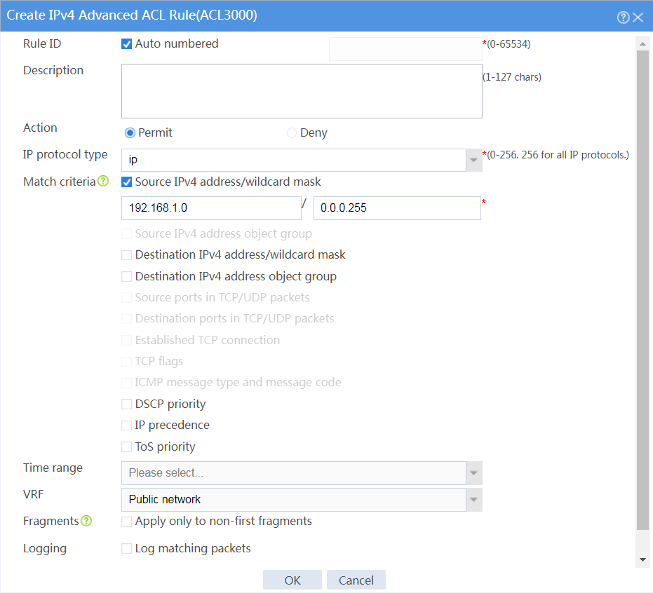
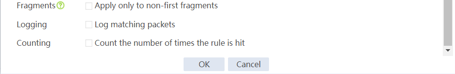
Figure 4 Adding rules to ACL 3000
# Click OK.
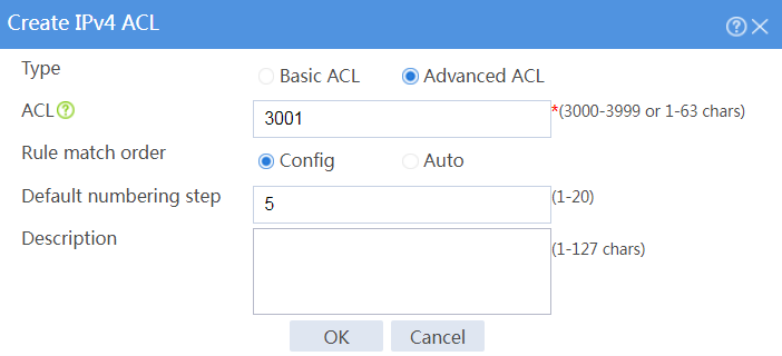
# Click Create to create an ACL to match user traffic from network B to the external network, as shown in Figure 5.
# Click OK, and then add ACL rules, as shown in Figure 6 and Figure 7.
Figure 6 Adding rules to ACL 3001
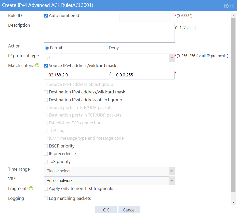
Figure 7 Adding rules to ACL 3001

# Click OK.
5. Configure PBR:
# On the top navigation bar, click Network.
# From the navigation pane, select Routing > PBR > IPv4 PBR.
# Click Create.
# In the dialog box that opens, configure the following parameters for the IPv4 PBR policy, as shown in Figure 8.
Figure 8 Creating an IPv4 PBR policy

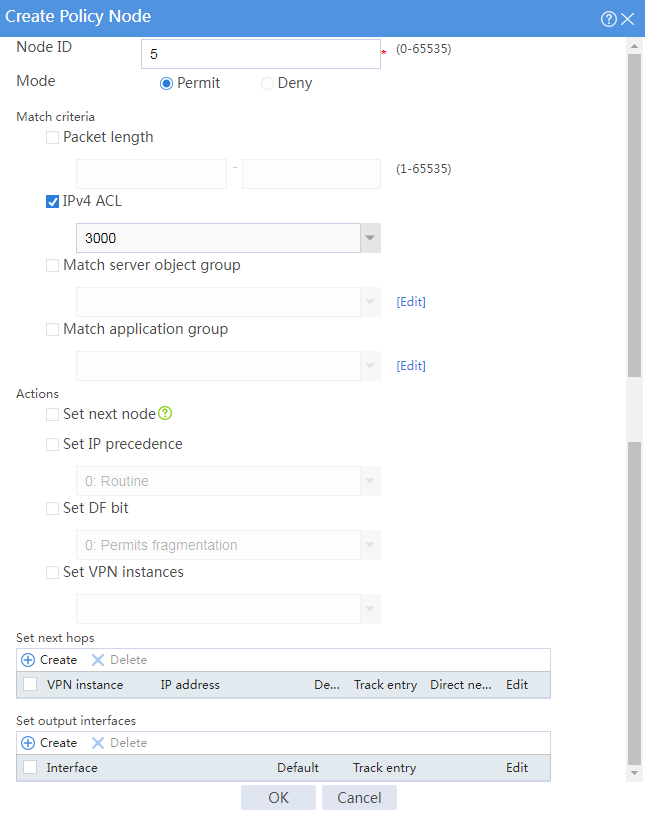
# Click Create to create policy node 5 to forward user traffic from network A to the external network, as shown in Figure 9.
Figure 9 Creating policy node 5
# Click Create in the Set next hops area, and configure the next hop settings as shown in Figure 10.
Figure 10 Setting the next hop

# Click OK to complete the next hop configuration.
# Click OK to complete the policy node configuration.
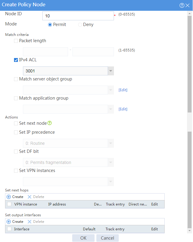
# Click Create to create policy node 10 to forward user traffic from network B to the external network, as shown in Figure 11.
Figure 11 Creating policy node 10
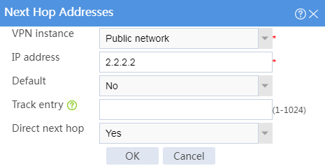
# Click Create in the Set next hops area, and configure the next hop settings as shown in Figure 12.
Figure 12 Setting the next hop
# Click OK to complete the next hop configuration.
# Click OK to complete the policy node configuration.
# Click OK to complete the IPv4 PBR policy configuration.
Configuring Device B
# Configure a static route to ensure that packets from the internal network to the external network can be forwarded to GE 1/0/1 on Device A. (Details not shown.)
Verifying the configuration
1. Use the tracert command to identify the path from a host in internal network A to external network IP address 3.3.3.3. Hop 3 is the access point IP address 1.1.1.2 of ISP link A.
C:\Users\abc>tracert 3.3.3.3
The path to 3.3.3.3 has a maximum of 30 hops.
1 1 ms 1 ms 1 ms 192.168.1.1
2 2 ms 2 ms 2 ms 192.168.3.2
3 4 ms 7 ms 6 ms 1.1.1.2
4 5 ms 5 ms 4 ms 3.3.3.3
Traceroute completed.
2. Use the tracert command to identify the path from a host in internal network B to external network IP address 3.3.3.3. Hop 3 is the access point IP address 2.2.2.2 of ISP link B.
C:\Users\xyz>tracert 3.3.3.3
The path to 3.3.3.3 has a maximum of 30 hops.
1 1 ms 1 ms 1 ms 192.168.2.1
2 2 ms 2 ms 2 ms 192.168.3.2
3 5 ms 6 ms 5 ms 2.2.2.2
4 6 ms 4 ms 5 ms 3.3.3.3
Traceroute completed.
