- Table of Contents
-
- H3C SecPath M9000 Multi Service Security Gateway Configuration Examples(V7)(E9X71)-6W700
- 00-Preface
- 01-About the configuration examples
- 02-Web Login Configuration Examples
- 03-Internet Access Through a Static IP Address Configuration Examples
- 04-Internet access through PPPoE configuration examples
- 05-License Configuration Examples
- 06-Signature Library Upgrade Configuration Examples
- 07-Software Upgrade Examples
- 08-Routing deployment configuration examples
- 09-Transparent deployment configuration examples
- 10-Static routing configuration examples
- 11-RIP configuration examples
- 12-OSPF configuration examples
- 13-BGP configuration examples
- 14-Policy-based routing configuration examples
- 15-Security Policy Configuration Examples
- 16-APR-Based Security Policy Configuration Examples
- 17-Object Group Configuration Examples
- 18-User identification configuration examples
- 19-Attack defense configuration examples
- 20-Request Limit Configuration Examples
- 21-IPS Configuration Examples
- 22-URL Filtering Configuration Examples
- 23-Anti-Virus Configuration Examples
- 24-File Filtering Configuration Examples
- 25-Data Filtering Configuration Examples
- 26-WAF Configuration Examples
- 27-IP Reputation Configuration Examples
- 28-APT Defense Configuration Examples
- 29-NetShare Control Configuration Examples
- 30-Bandwidth Management Configuration Examples
- 31-IPsec configuration examples
- 32-SSL VPN IP access configuration examples
- 32-SSL VPN TCP access configuration examples
- 32-SSL VPN Web access configuration examples
- 33-L2TP Configuration Examples
- 34-NAT configuration examples
- 35-NPTv6 Configuration Examples
- 36-Policy-based NAT configuration examples
- 37-NAT hairpin configuration examples
- 38-NAT Flow Logging Configuration Examples
- 39-Inbound Link Load Balancing Configuration Examples
- 40-Outbound Link Load Balancing Configuration Examples
- 41-Server Load Balancing Configuration Examples
- 42-Transparent DNS Proxy Configuration Examples
- 43-Hot Backup Configuration Examples
- 44-Context Configuration Examples
- 45-DNS configuration examples
- 46-Server Connection Detection Configuration Examples
- 47-Connection Limit Configuration Examples
- 48-Public key management configuration examples
- 49-SSL Decryption Configuration Examples
- 50-MAC Address Learning Through a Layer 3 Device Configuration Examples
- 51-4G Configuration Examples
- 52-WLAN Configuration Examples
- Related Documents
-
| Title | Size | Download |
|---|---|---|
| 41-Server Load Balancing Configuration Examples | 1.09 MB |
Server load balancing configuration examples
Contents
· Example: Configuring Layer 4 server load balancing
· Example: Configuring Layer 7 server load balancing
The following information provides server load balancing configuration examples.
Server load balancing is classified into Layer 4 server load balancing and Layer 7 server load balancing.
· Layer 4 server load balancing—Implemented based on streams. It distributes packets in the same stream to the same server. Layer 4 server load balancing cannot distribute Layer 7 services based on contents.
· Layer 7 server load balancing—Implemented based on contents. It analyzes packet contents, distributes packets one by one based on the contents, and distributes connections to the specified server according to the predefined policies. Layer 7 server load balancing applies load balancing services to a large scope.
Server load balancing supports IPv4 and IPv6, but does not support IPv4-to-IPv6 or IPv6-to-IPv4 translation.
The virtual server types supported by server load balancing include IP, TCP, UDP, HTTP, Performance (HTTP), HTTPS, and HTTP redirection. IP, TCP, and UDP, are called Layer 4 server load balancing. HTTP, Performance (HTTP), HTTPS, and HTTP redirection are called Layer 7 server load balancing.
This document is not restricted to specific software or hardware versions. Procedures and information in the examples might be slightly different depending on the software or hardware version of the device.
The configuration examples were created and verified in a lab environment, and all the devices were started with the factory default configuration. When you are working on a live network, make sure you understand the potential impact of every command on your network.
The following information is provided based on the assumption that you have basic knowledge of the server load balancing feature.
Example: Configuring Layer 4 server load balancing
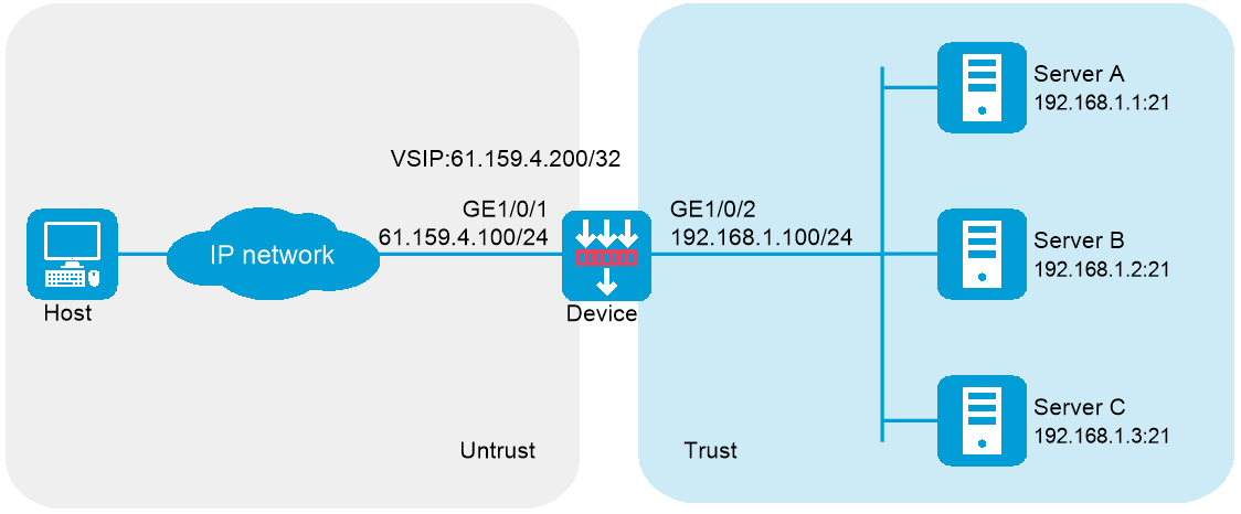
Network configuration
As shown in Figure 1, an enterprise uses Server A, Server B, and Server C to provide FTP services. Configure server load balancing to load balance FTP requests from Host among the servers based on source address. For example, enable the device to assign FTP requests sourced from 62.159.4.0/24 and 63.159.4.0/24 to Server A and Server B, respectively; enable the device to assign FTP requests with other source addresses to Server C.
Software versions used
This configuration example was created and verified on E8371 of the F5000-AI160 device.
This configuration example was created and verified on E9671 of the M9000-X06 device.
Procedure
1. Assign IP addresses to interfaces and add the interfaces to security zones.
# On the top navigation bar, click Network.
# From the navigation pane, select Interface Configuration > Interfaces.
# Click the Edit icon for GE 1/0/1.
# In the dialog box that opens, configure the interface:
¡ Select the Untrust security zone.
¡ On the IPv4 Address tab, enter the IP address and mask length of the interface. In this example, enter 61.159.4.100/24.
¡ Use the default settings for other parameters.
¡ Click OK.
# Add GE 1/0/2 to the Trust security zone and set its IP address to 192.168.1.100/24 in the same way you configure GE 1/0/1.
2. Configure security policies.
# On the top navigation bar, click Policies.
# From the navigation pane, select Security Policies > Security Policies.
# Click Create.
# In the dialog box that opens, configure a security policy named Untrust-to-Trust:
¡ Enter policy name Untrust-to-Trust.
¡ Select type IPv4.
¡ Select source zone Untrust.
¡ Select destination zone Trust.
¡ Enter destination IPv4 address 61.159.4.0/24.
¡ Select action Permit.
¡ Use the default settings for other parameters.
¡ Click OK.
# Configure a security policy named Local-to-Trust:
¡ Enter policy name Local-to-Trust.
¡ Select type IPv4.
¡ Select source zone Local.
¡ Select destination zone Trust.
¡ Enter destination IPv4 address 192.168.1.0/24.
¡ Select action Permit.
¡ Use the default settings for other parameters.
¡ Click OK.
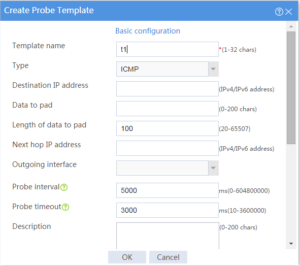
3. Create an ICMP-type probe template.
# On the top navigation bar, click Objects.
# From the navigation pane, select Health Monitoring.
# Click Create to configure the probe template t1 as shown in Figure 2.
Figure 2 Creating probe template t1

# Click OK.
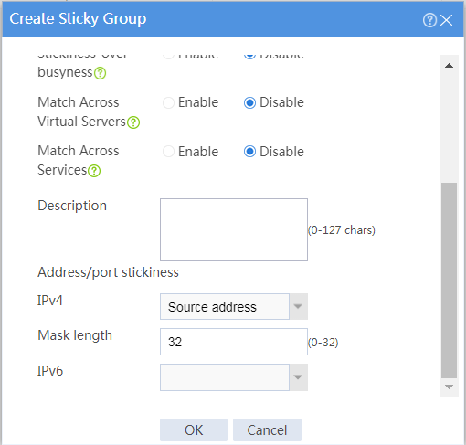
4. Create an address- and port-type sticky group.
# On the top navigation bar, click Objects.
# From the navigation pane, select Load Balancing > Sticky Groups.
# Click Create to configure the sticky group sticky_group as shown in Figure 3.
Figure 3 Creating sticky group sticky_group (part 1)
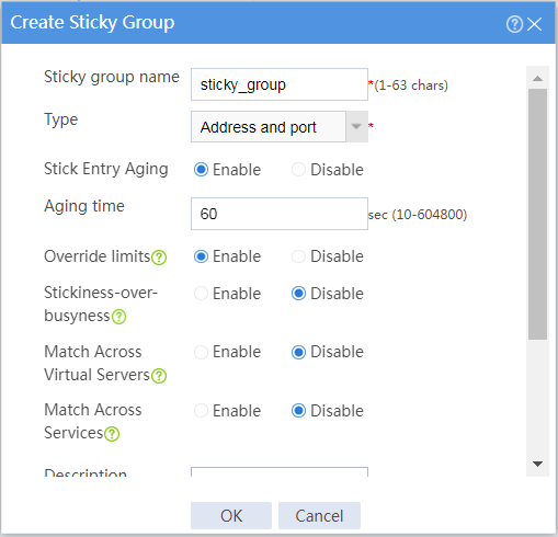
Figure 4 Creating sticky group sticky_group (part 2)
# Click OK.
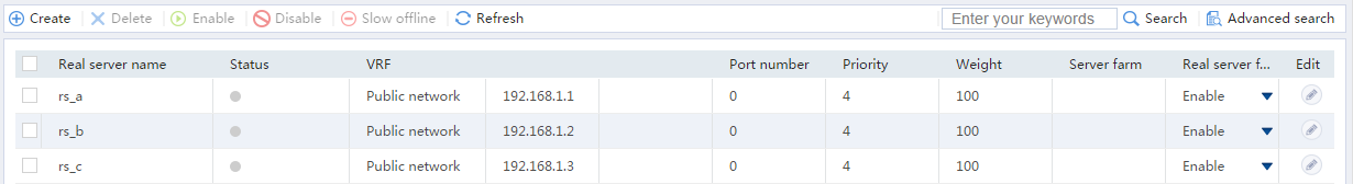
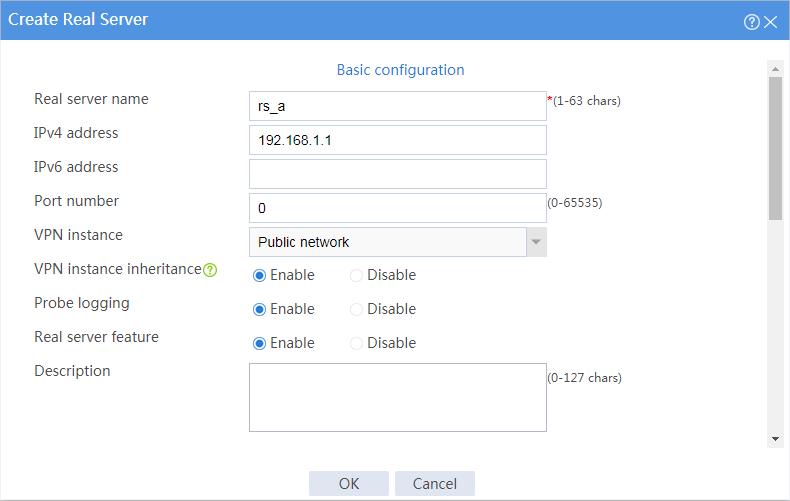
5. Create real servers.
# On the top navigation bar, click Policies.
# From the navigation pane, select Server Load Balancing > Real Servers.
# Click Create to configure the real server rs_a as shown in Figure 5.
Figure 5 Creating real server rs_a

# Click OK.
# Configure real server rs_b and set its IP address to 192.168.1.2 in the same way you configure real server rs_a.
# Configure real server rs_c and set its IP address to 192.168.1.3 in the same way you configure real server rs_a.
# Display the configured real servers as shown in Figure 6.
Figure 6 Displaying the configured real servers
6. Create server farms.
# On the top navigation bar, click Policies.
# From the navigation pane, select Server Load Balancing > Server Farms.
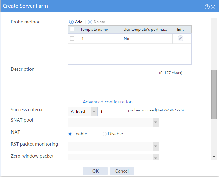
# Click Create to configure the server farm sf1 as shown in Figure 7 and Figure 8.
Figure 7 Creating server farm sf1 (I)

Figure 8 Creating server farm sf1 (II)

# Click OK.
# Configure server farm sf2 and specify real server rs_b in the same way you configure server farm sf1.
# Configure server farm sf3 and specify real server rs_c in the same way you configure server farm sf1.
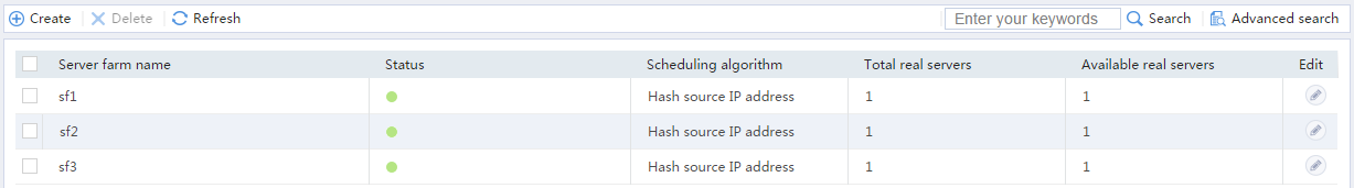
# Display the configured server farms as shown in Figure 9.
Figure 9 Displaying the configured server farms

7. Create classes.
# On the top navigation bar, click Policies.
# From the navigation pane, select Server Load Balancing > Advanced Policies.
# Click the Class tab.
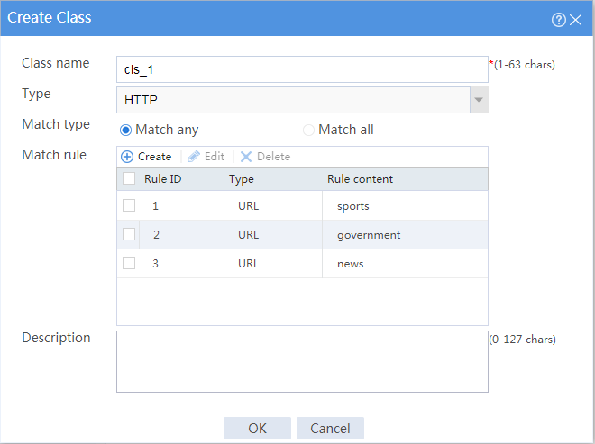
# Click Create to configure the class cls_1 as shown in Figure 10.
Figure 10 Creating class cls_1
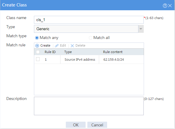
# Click OK.
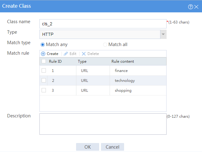
# Click Create to configure the class cls_2 as shown in Figure 11.
Figure 11 Creating class cls_2
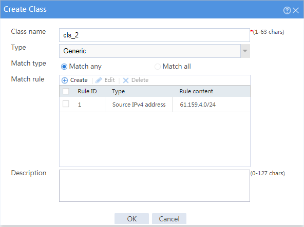
# Click OK.
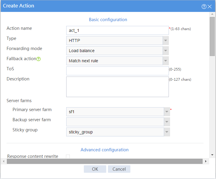
8. Create actions.
# On the top navigation bar, click Policies.
# From the navigation pane, select Server Load Balancing > Advanced Policies.
# Click the Action tab.
# Click Create to configure the action act_1 as shown in Figure 12.
Figure 12 Creating action act_1
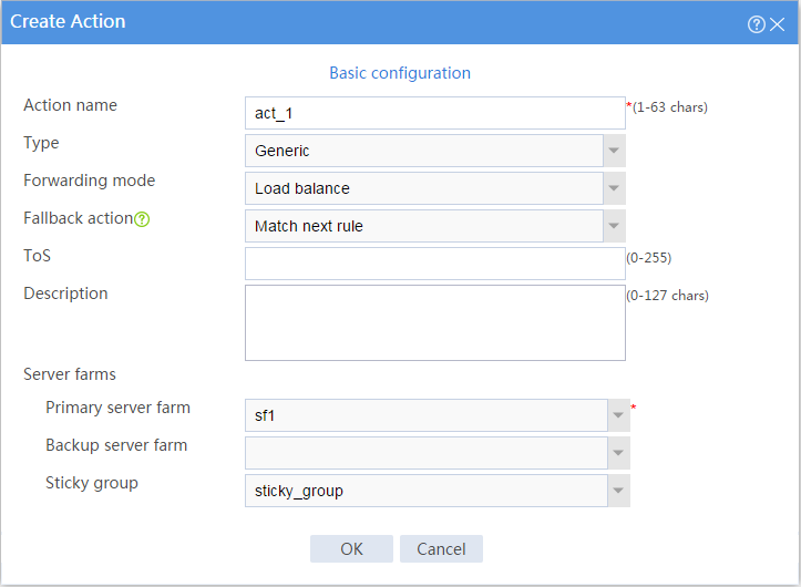
# Click OK.
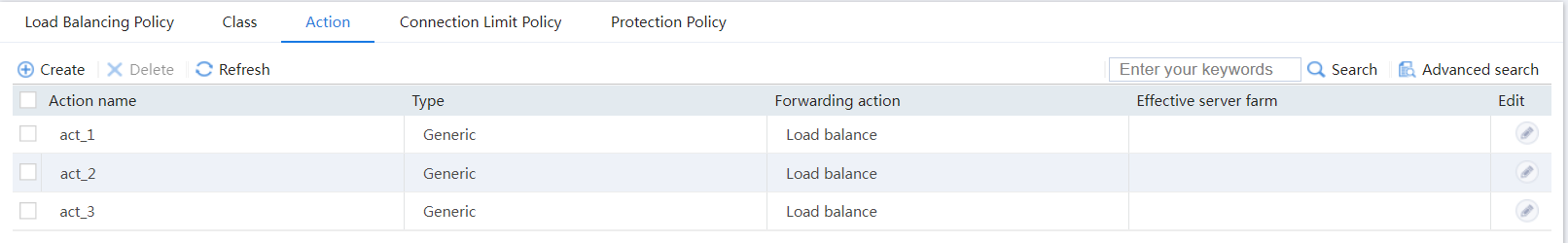
# Configure action act_2 and specify primary server farm sf2 in the same way you configure action act_1.
# Configure action act_3 and specify primary server farm sf3 in the same way you configure action act_1.
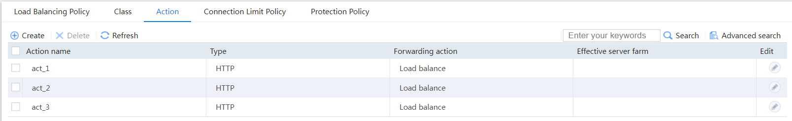
# Display the configured actions as shown in Figure 13.
Figure 13 Displaying the configured actions
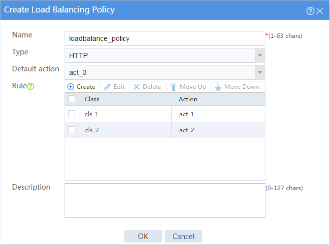
9. Create a load balancing policy.
# On the top navigation bar, click Policies.
# From the navigation pane, select Server Load Balancing > Advanced Policies.
# Click the Load Balancing Policy tab.
# Click Create to configure the load balancing policy loadbalance_policy as shown in Figure 14.
Figure 14 Creating load balancing policy loadbalance_policy
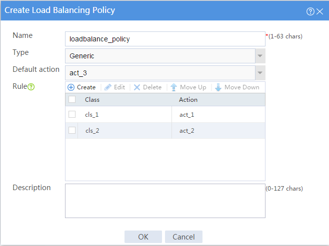
# Click OK.
10. Create a virtual server.
# On the top navigation bar, click Policies.
# From the navigation pane, select Server Load Balancing > Virtual Servers.
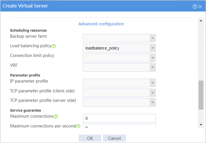
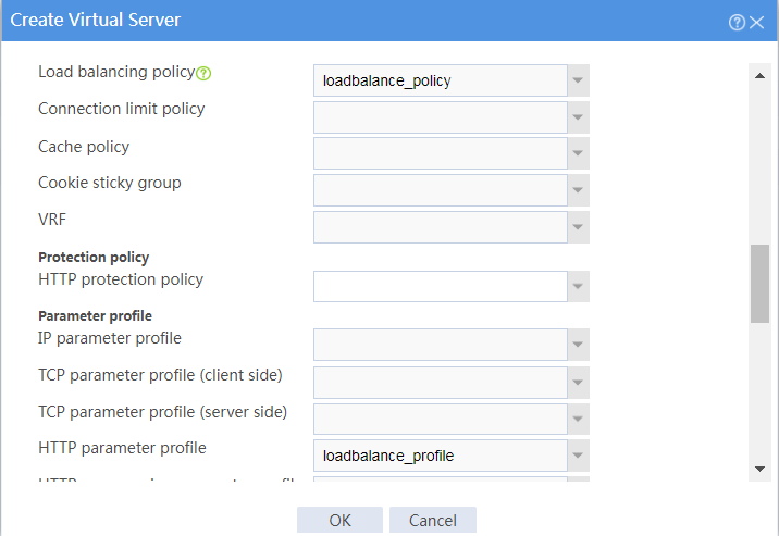
# Click Create to configure the virtual server vs as shown in Figure 15 and Figure 17.
Figure 15 Creating virtual server vs (basic configuration, part 1)
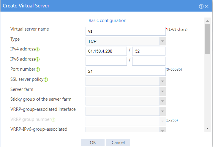
Figure 16 Creating virtual server vs (basic configuration, part 2)
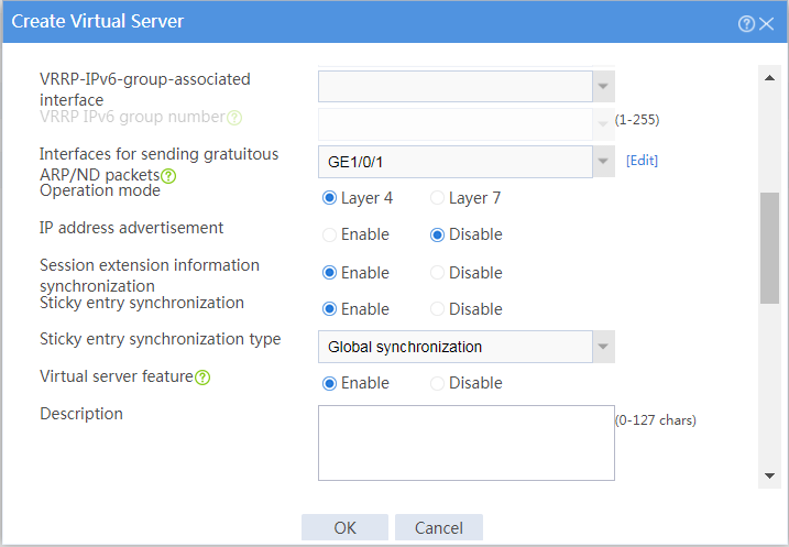
Figure 17 Creating virtual server vs (advanced configuration)
# Click OK.
Verifying the configuration
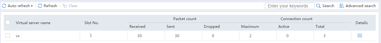
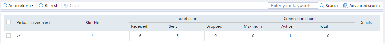
1. Verify that Device assigns Sever A the FTP requests sourced from host IP address 62.159.4.1 and destined to virtual server IP address 61.159.4.100.
# Access virtual server IP address 61.159.4.100 on the host with IP address 62.159.4.1.
C:\Users\system>ftp 61.159.4.200
Connected to 61.159.4.200.
220 FTP service ready.
User (61.159.4.200:(none)): admin
331 Password required for admin.
Password:
230 User logged in.
ftp>
# On the top navigation bar, click Monitor.
# From the navigation pane, select Statistics > Server LB Statistics > Virtual Servers.
Figure 18 Displaying virtual server statistics
# On the top navigation bar, click Monitor.
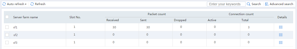
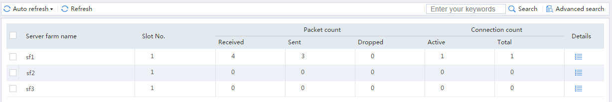
# From the navigation pane, select Statistics > Server LB Statistics > Servers Farms. You can see that Device assigns FTP requests sourced from 62.159.4.1 to server farm sf1.
Figure 19 Displaying server farm statistics
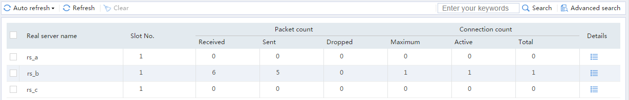
# On the top navigation bar, click Monitor.
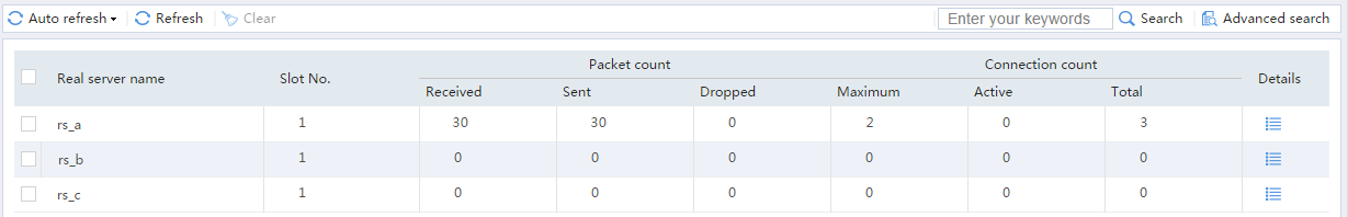
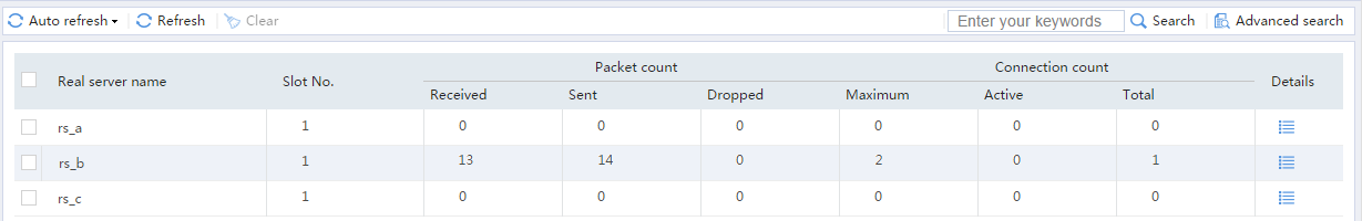
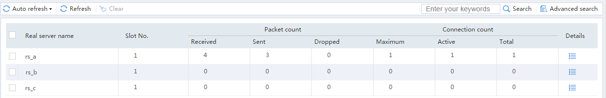
# From the navigation pane, select Statistics > Server LB Statistics > Real Servers. You can see that Device assigns FTP requests sourced from 62.159.4.1 to real server rs_a.
Figure 20 Displaying real server statistics
2. Verify that Device assigns Sever B the FTP requests sourced from host IP address 63.159.4.1 and destined to virtual server IP address 61.159.4.200.
# Access virtual server IP address 61.159.4.200 on the host with IP address 63.159.4.1.
C:\Users\system>ftp 61.159.4.200
Connected to 61.159.4.200.
220 FTP service ready.
User (61.159.4.200:(none)): admin
331 Password required for admin.
Password:
230 User logged in.
ftp>
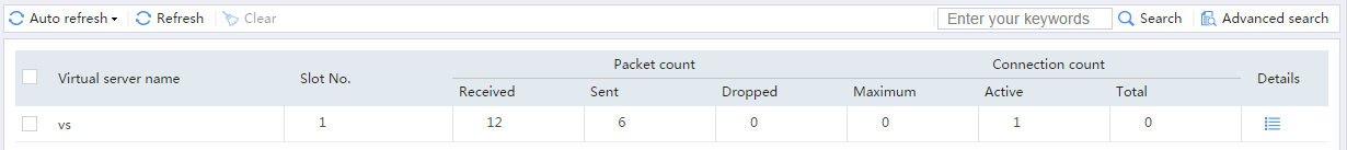
# On the top navigation bar, click Monitor.
# From the navigation pane, select Statistics > Server LB Statistics > Virtual Servers.
Figure 21 Displaying virtual server statistics
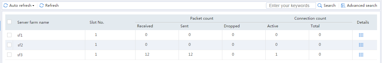
# On the top navigation bar, click Monitor.
# From the navigation pane, select Statistics > Server LB Statistics > Servers Farms. You can see that Device assigns FTP requests sourced from 63.159.4.1 to server farm sf2.
Figure 22 Displaying server farm statistics

# On the top navigation bar, click Monitor.
# From the navigation pane, select Statistics > Server LB Statistics > Real Servers. You can see that Device assigns FTP requests sourced from 63.159.4.1 to real server rs_b.
Figure 23 Displaying real server statistics
3. Verify that Device assigns Sever C the FTP requests sourced from host IP address 64.159.4.1 and destined to virtual server IP address 61.159.4.200.
# Access virtual server IP address 61.159.4.200 on the host with IP address 64.159.4.1.
C:\Users\system>ftp 61.159.4.200
Connected to 61.159.4.200.
220 FTP service ready.
User (61.159.4.200:(none)): admin
331 Password required for admin.
Password:
230 User logged in.
ftp>
# On the top navigation bar, click Monitor.
# From the navigation pane, select Statistics > Server LB Statistics > Virtual Servers.
Figure 24 Displaying virtual server statistics

# On the top navigation bar, click Monitor.
# From the navigation pane, select Statistics > Server LB Statistics > Servers Farms. You can see that Device assigns FTP requests sourced from 64.159.4.1 to server farm sf3.
Figure 25 Displaying server farm statistics

# On the top navigation bar, click Monitor.
# From the navigation pane, select Statistics > Server LB Statistics > Real Servers. You can see that Device assigns FTP requests sourced from 64.159.4.1 to real server rs_c.
Figure 26 Displaying real server statistics

Network configuration
As shown in Figure 27, an enterprise uses Server A, Server B, and Server C to provide HTTP services. Configure server load balancing to load balance HTTP requests from Host. The device assigns requests whose URLs contain sports, government, and news to Server A; assigns requests whose URLs contain finance, technology, and shopping to Server B; and assigns other requests to Server C.

Software versions used
This configuration example was created and verified on E8371 of the F5000-AI160 device.
This configuration example was created and verified on E9671 of the M9000-X06 device.
Procedure
1. Assign IP addresses to interfaces and add the interfaces to security zones.
# On the top navigation bar, click Network.
# From the navigation pane, select Interface Configuration > Interfaces.
# Click the Edit icon for GE 1/0/1.
# In the dialog box that opens, configure the interface:
¡ Select the Untrust security zone.
¡ On the IPv4 Address tab, enter the IP address and mask length of the interface. In this example, enter 61.159.4.100/24.
¡ Use the default settings for other parameters.
¡ Click OK.
# Add GE 1/0/2 to the Trust security zone and set its IP address to 192.168.1.100/24 in the same way you configure GE 1/0/1.
2. Configure security policies.
# On the top navigation bar, click Policies.
# From the navigation pane, select Security Policies > Security Policies.
# Click Create.
# In the dialog box that opens, configure a security policy named Untrust-to-Local:
¡ Enter policy name Untrust-to-Local.
¡ Select type IPv4.
¡ Select source zone Untrust.
¡ Select destination zone Local.
¡ Enter destination IPv4 address 61.159.4.0/24.
¡ Select action Permit.
¡ Use the default settings for other parameters.
¡ Click OK.
# Configure a security policy named Local-to-Trust:
¡ Enter policy name Local-to-Trust.
¡ Select type IPv4.
¡ Select source zone Local.
¡ Select destination zone Trust.
¡ Enter destination IPv4 address 192.168.1.0/24.
¡ Select action Permit.
¡ Use the default settings for other parameters.
¡ Click OK.
3. Create an ICMP-type probe template.
# On the top navigation bar, click Objects.
# From the navigation pane, select Health Monitoring.
# Click Create to configure the probe template t1 as shown in Figure 28.
Figure 28 Creating probe template t1
# Click OK.
4. Create an HTTP cookie sticky group.
# On the top navigation bar, click Objects.
# From the navigation pane, select Load Balancing > Sticky Groups.
# Click Create to configure the sticky group sticky_group as shown in Figure 29.
Figure 29 Creating sticky group sticky_group

# Click OK.
5. Create real servers.
# On the top navigation bar, click Policies.
# From the navigation pane, select Server Load Balancing > Real Servers.
# Click Create to configure the real server rs_a as shown in Figure 30.
Figure 30 Creating real server rs_a
# Click OK.
# Configure real server rs_b and set its IP address to 192.168.1.2 in the same way you configure real server rs_a.
# Configure real server rs_c and set its IP address to 192.168.1.3 in the same way you configure real server rs_a.
# Display the configured real servers as shown in Figure 31.
Figure 31 Displaying the configured real servers

6. Create server farms.
# On the top navigation bar, click Policies.
# From the navigation pane, select Server Load Balancing > Server Farms.
# Click Create to configure the server farm sf1 as shown in Figure 32 and Figure 33.
Figure 32 Creating server farm sf1 (I)
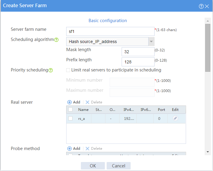
Figure 33 Creating server farm sf1 (II)
# Click OK.
# Configure server farm sf2 and specify real server rs_b in the same way you configure server farm sf1.
# Configure server farm sf3 and specify real server rs_c in the same way you configure server farm sf1.
# Display the configured server farms as shown in Figure 34.
Figure 34 Displaying the configured server farms
7. Create classes.
# On the top navigation bar, click Policies.
# From the navigation pane, select Server Load Balancing > Advanced Policies.
# Click the Class tab.
# Click Create to configure the class cls_1 as shown in Figure 35.
Figure 35 Creating class cls_1
# Click OK.
# Click Create to configure the class cls_2 as shown in Figure 36.
Figure 36 Creating class cls_2
# Click OK.
8. Create actions.
# On the top navigation bar, click Policies.
# From the navigation pane, select Server Load Balancing > Advanced Policies.
# Click the Action tab.
# Click Create to configure the action act_1 as shown in Figure 37.
Figure 37 Creating action act_1
# Click OK.
# Configure action act_2 and specify primary server farm sf2 in the same way you configure action act_1.
# Configure action act_3 and specify primary server farm sf3 in the same way you configure action act_1.
# Display the configured actions as shown in Figure 38.
Figure 38 Displaying the configured actions
9. Create a load balancing policy.
# On the top navigation bar, click Policies.
# From the navigation pane, select Server Load Balancing > Advanced Policies.
# Click the Load Balancing Policy tab.
# Click Create to configure the load balancing policy loadbalance_policy as shown in Figure 39.
Figure 39 Creating load balancing policy loadbalance_policy
# Click OK.
10. Create an HTTP-type parameter profile.
# On the top navigation bar, click Policies.
# From the navigation pane, select Server Load Balancing > Parameter Profiles.
# Click Create to configure the parameter profile loadbalance_profile as shown in Figure 40.
Figure 40 Creating parameter profile loadbalance_profile

# Click OK.
11. Create a virtual server.
# On the top navigation bar, click Policies.
# From the navigation pane, select Server Load Balancing > Virtual Servers.
# Click Create to configure the virtual server vs as shown in Figure 41 and Figure 43.
Figure 41 Creating virtual server vs (basic configuration, part 1)
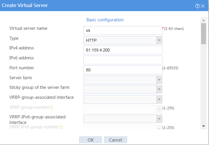
Figure 42 Creating virtual server vs (basic configuration, part 2)
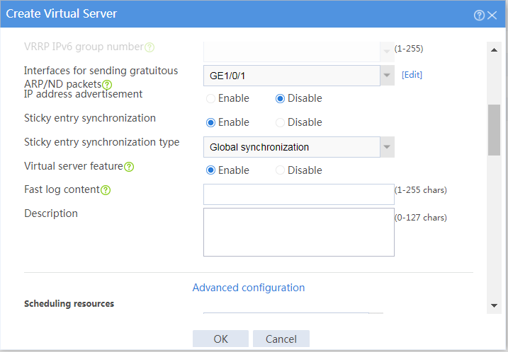
Figure 43 Creating virtual server vs (advanced configuration)
# Click OK.
Verifying the configuration
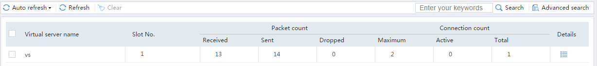
1. Verify that the device assigns Sever A the HTTP request with URL http://61.159.4.200/sports/.
# Access http://61.159.4.200/sports/ on Host.
Figure 44 Accessing the HTTP service
![]()
# On the top navigation bar, click Monitor.
# From the navigation pane, select Statistics > Server LB Statistics > Virtual Servers.
Figure 45 Displaying virtual server statistics

# On the top navigation bar, click Monitor.
# From the navigation pane, select Statistics > Server LB Statistics > Servers Farms. You can see that the device assigns the HTTP request containing URL http://61.159.4.200/sports/ to server farm sf1.
Figure 46 Displaying server farm statistics
# On the top navigation bar, click Monitor.
# From the navigation pane, select Statistics > Server LB Statistics > Real Servers. You can see that the device assigns the HTTP request containing URL http://61.159.4.200/sports/ to real server rs_a.
Figure 47 Displaying real server statistics
2. Verify that the device assigns Sever B the HTTP request with URL http://61.159.4.200/finance/.
# Access http://61.159.4.200/finance/ on Host.
Figure 48 Accessing the HTTP service
![]()
# On the top navigation bar, click Monitor.
# From the navigation pane, select Statistics > Server LB Statistics > Virtual Servers.
Figure 49 Displaying virtual server statistics
# On the top navigation bar, click Monitor.
# From the navigation pane, select Statistics > Server LB Statistics > Servers Farms. You can see that the device assigns the HTTP request containing URL http://61.159.4.200/finance/ to server farm sf2.
Figure 50 Displaying server farm statistics

# On the top navigation bar, click Monitor.
# From the navigation pane, select Statistics > Server LB Statistics > Real Servers. You can see that the device assigns the HTTP request containing URL http://61.159.4.200/finance/ to real server rs_b.
Figure 51 Displaying real server statistics
3. Verify that the device assigns Sever C the HTTP request with URL http://61.159.4.200/education/.
# Access http://61.159.4.200/education/ on Host.
Figure 52 Accessing the HTTP service
![]()
# On the top navigation bar, click Monitor.
# From the navigation pane, select Statistics > Server LB Statistics > Virtual Servers.
Figure 53 Displaying virtual server statistics
# On the top navigation bar, click Monitor.
# From the navigation pane, select Statistics > Server LB Statistics > Servers Farms. You can see that the device assigns the HTTP request containing URL http://61.159.4.200/education/ to server farm sf3.
Figure 54 Displaying server farm statistics
# On the top navigation bar, click Monitor.
# From the navigation pane, select Statistics > Server LB Statistics > Real Servers. You can see that the device assigns the HTTP request containing URL http://61.159.4.200/education/ to real server rs_c.
Figure 55 Displaying real server statistics

