- Table of Contents
-
- 08-Configuration Examples
- 01-Web Login Configuration Examples
- 02-Internet Access Through a Static IP Address Configuration Examples
- 03-Internet access through PPPoE configuration examples
- 04-Signature Library Upgrade Configuration Examples
- 04-Software Upgrade Examples(only for F50X0-D and F5000-AK5X5 firewalls)
- 05-Software Upgrade Examples
- 06-Static routing configuration examples
- 07-OSPF configuration examples
- 08-BGP configuration examples
- 09-RIP configuration examples
- 10-DHCP configuration examples
- 11-DNS configuration examples
- 12-Object Group Configuration Examples
- 13-Public key management configuration examples
- 14-Security Policy Configuration Examples
- 15-Attack defense configuration examples
- 16-Connection Limit Configuration Examples
- 17-IPS Configuration Examples
- 18-URL Filtering Configuration Examples
- 19-Anti-Virus Configuration Examples
- 20-Data Filtering Configuration Examples
- 21-File Filtering Configuration Examples
- 22-APR-Based Security Policy Configuration Examples
- 23-Bandwidth Management Configuration Examples
- 24-NAT configuration examples
- 25-NAT hairpin configuration examples
- 26-IPsec configuration examples
- 27-SSL VPN configuration examples
- 28-Server Load Balancing Configuration Examples
- 29-Outbound Link Load Balancing Configuration Examples
- 30-Inbound Link Load Balancing Configuration Examples
- 31-Transparent DNS Proxy Configuration Examples
- 32-Context Configuration Examples
- 32-Context Configuration Examples(only for F50X0-D and F5000-AK5X5 firewalls)
- 33-IRF configuration examples
- 34-High Availability Group Configuration Examples
- 35-NAT Flow Logging Configuration Examples
- 36-User identification configuration examples
- 37-Server Connection Detection Configuration Examples
- 38-IP Reputation Configuration Examples
- 39-NPTv6 Configuration Examples
- 40-SSL Decryption Configuration Examples
- 41-MAC Address Learning Through a Layer 3 Device Configuration Examples
- 42-WAF Configuration Examples
- 43-NetShare Control Configuration Examples
- 44-4G Configuration Examples
- 45-WLAN Configuration Examples
- Related Documents
-
| Title | Size | Download |
|---|---|---|
| 45-WLAN Configuration Examples | 59.77 KB |
WLAN configuration examples
The following information provides WLAN configuration examples.
This document is not restricted to specific software or hardware versions. Procedures and information in the examples might be slightly different depending on the software or hardware version of the device.
The configuration examples were created and verified in a lab environment, and all the devices were started with the factory default configuration. When you are working on a live network, make sure you understand the potential impact of every command on your network.
The following information is provided based on the assumption that you have basic knowledge of the WLAN feature.
General restrictions and guidelines
For clients to discover the SSID provided by the device, do not enable SSID hidden on the device.
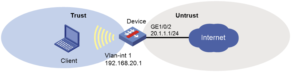
Network configuration
As shown in Figure 1, the device connects to the LAN and Internet through security zones Trust and Untrust, respectively.
Configure wireless services on the device for the client to access the Internet.
Software versions used
This configuration example was created and verified on Feature 9602P17 of an F100-C-A6-WL device.
Procedure
1. Assign IP addresses to interfaces and add the interfaces to security zones.
# On the top navigation bar, click Network.
# From the navigation pane, select Link > VLANs.
# Click the Vlan-interface1 link for VLAN 1.
# In the dialog box that opens, configure the interface:
a. Select the Trust security zone.
b. On the IPv4 Address tab, enter the IP address and mask of the interface. In this example, enter 192.168.20.1/24.
c. Retain the default settings for the other fields.
d. Click OK.
# From the navigation pane, select Interface Configuration > Interfaces.
# Click the Edit icon for GE 1/0/2.
# In the dialog box that opens, configure the interface:
a. Select the Untrust security zone.
b. On the IPv4 Address tab, enter the IP address and mask of the interface. In this example, enter 20.1.1.1/24.
c. Retain the default settings for the other fields.
d. Click OK.
2. Create a security policy.
# On the top navigation bar, click Policies.
# From the navigation pane, select Security Policies > Security Policies.
# Click Create.
# In the dialog box that opens, create a security policy as follows:
¡ Specify the policy name as test-a.
¡ Select Trust as the source security zone.
¡ Select Untrust as the destination security zone.
¡ Select IPv4 as the type.
¡ Select Permit as the action.
¡ Specify 192.168.20.0/24 as the source IPv4 address.
¡ Retain the default settings for the other fields.
# Click OK.
3. Configure wireless settings.
# On the top navigation bar, click Network.
# From the navigation pane, select Wireless > Wireless Settings.
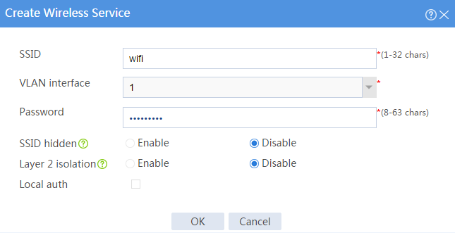
# Click Create.
# In the dialog box that appears, configure a wireless service:
¡ Enter SSID wifi.
¡ Select VLAN interface 1.
¡ Enter password 123456789.
¡ Retain the default settings for the other fields.
# Click OK.
Figure 2 Creating a wireless service
4. Configure DHCP settings.
# On the top navigation bar, click Network.
# From the navigation pane, select DHCP > DHCP Address Pools.
# Click Create.
# In the dialog box that opens, enter address pool name wifi and then click OK.
# Configure the address pool:
a. On the Address Allocation tab, set the subnet for dynamic allocation to 192.168.20.0/255.255.255.0 and then click OK.
b. On the Address Pool Options tab, configure the following parameters:
- Set the gateway address to 192.168.20.1.
- Set the DNS server address to 114.114.114.114.
- Retain the default settings for the other fields.
c. Click OK.
5. Configure DNS settings.
# On the top navigation bar, click Network.
# From the navigation pane, select DNS > DNS Client.
# On the page that opens, enter domain server address 114.114.114.114, and then click the plus icon to add a DNS server.
# From the navigation pane, select DNS > Advanced Settings.
# On the page that opens, select Enable for DNS proxy and then click OK.
Verifying the configuration
Verify that the client can access the WLAN and visit the Internet. To view client information, such as online client information, client statistics, SNR distribution, and rate distribution, click Network on the top navigation bar and then select Wireless > Wireless Info from the navigation pane.