- Table of Contents
-
- 08-Configuration Examples
- 01-Web Login Configuration Examples
- 02-Internet Access Through a Static IP Address Configuration Examples
- 03-Internet access through PPPoE configuration examples
- 04-Signature Library Upgrade Configuration Examples
- 04-Software Upgrade Examples(only for F50X0-D and F5000-AK5X5 firewalls)
- 05-Software Upgrade Examples
- 06-Static routing configuration examples
- 07-OSPF configuration examples
- 08-BGP configuration examples
- 09-RIP configuration examples
- 10-DHCP configuration examples
- 11-DNS configuration examples
- 12-Object Group Configuration Examples
- 13-Public key management configuration examples
- 14-Security Policy Configuration Examples
- 15-Attack defense configuration examples
- 16-Connection Limit Configuration Examples
- 17-IPS Configuration Examples
- 18-URL Filtering Configuration Examples
- 19-Anti-Virus Configuration Examples
- 20-Data Filtering Configuration Examples
- 21-File Filtering Configuration Examples
- 22-APR-Based Security Policy Configuration Examples
- 23-Bandwidth Management Configuration Examples
- 24-NAT configuration examples
- 25-NAT hairpin configuration examples
- 26-IPsec configuration examples
- 27-SSL VPN configuration examples
- 28-Server Load Balancing Configuration Examples
- 29-Outbound Link Load Balancing Configuration Examples
- 30-Inbound Link Load Balancing Configuration Examples
- 31-Transparent DNS Proxy Configuration Examples
- 32-Context Configuration Examples
- 32-Context Configuration Examples(only for F50X0-D and F5000-AK5X5 firewalls)
- 33-IRF configuration examples
- 34-High Availability Group Configuration Examples
- 35-NAT Flow Logging Configuration Examples
- 36-User identification configuration examples
- 37-Server Connection Detection Configuration Examples
- 38-IP Reputation Configuration Examples
- 39-NPTv6 Configuration Examples
- 40-SSL Decryption Configuration Examples
- 41-MAC Address Learning Through a Layer 3 Device Configuration Examples
- 42-WAF Configuration Examples
- 43-NetShare Control Configuration Examples
- 44-4G Configuration Examples
- 45-WLAN Configuration Examples
- Related Documents
-
| Title | Size | Download |
|---|---|---|
| 27-SSL VPN configuration examples | 2.56 MB |
SSL VPN configuration examples
The following information provides SSL VPN configuration examples.
This document is not restricted to specific software or hardware versions. Procedure and information in the examples might be slightly different depending on the software or hardware version of the device.
The configuration examples were created and verified in a lab environment, and all the devices were started with the factory default configuration. When you are working on a live network, make sure you understand the potential impact of every command on your network.
The following information is provided based on the assumption that you have basic knowledge of SSL VPN.
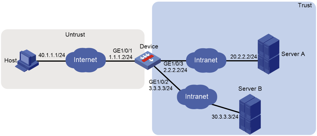
Network configuration
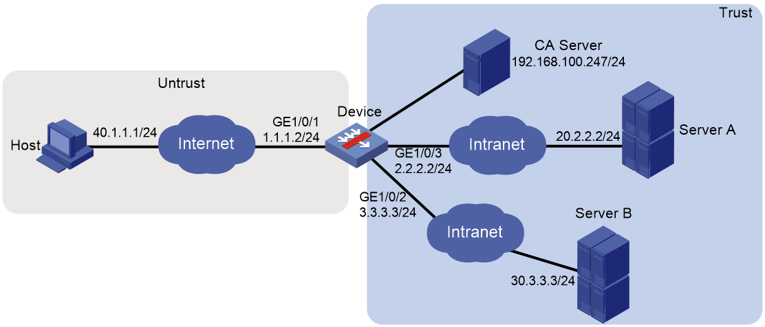
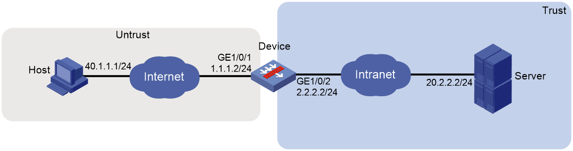
As shown in Figure 1, the device acts as the SSL VPN gateway that connects the public network and the private network. Users need to access resources on internal Web servers Server A and Server B. Both servers use HTTP over port 80.
Configure the SSL VPN Web access service on the device to allow users to access Server A and Server B in Web access mode.
Configure the device to perform local authentication and authorization for Web access users.
The device uses a self-signed SSL server certificate.
Software versions used
This configuration example was created and verified on E9345 of the F1060 device.
Procedure
Configuring the device
1. Assign IP addresses to interfaces and add the interfaces to security zones:
# On the top navigation bar, click Network.
# From the navigation pane, select Interface Configuration > Interfaces.
# Click the Edit icon for GE 1/0/1.
# In the dialog box that opens, configure the interface:
a. On the Basic Configuration tab, select the Trust security zone.
b. On the IPv4 Address tab, enter the IP address and mask length of the interface. In this example, enter 1.1.1.2/24.
c. Click OK.
# Add GE 1/0/2 to the Trust security zone and set its IP address to 3.3.3.3/24 in the same way you configure GE 1/0/1.
# Add GE 1/0/3 to the Trust security zone and set its IP address to 2.2.2.2/24 in the same way you configure GE 1/0/1.
2. Configure the security policy between the Trust and Untrust security zones. Make sure the Trust and Untrust security zones can communicate with each other.
3. Configure the SSL VPN gateway:
# On the top navigation bar, click Network.
# From the navigation pane, select SSL VPN > SSL VPN Gateways.
# Click Create.
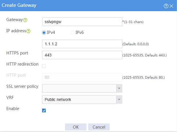
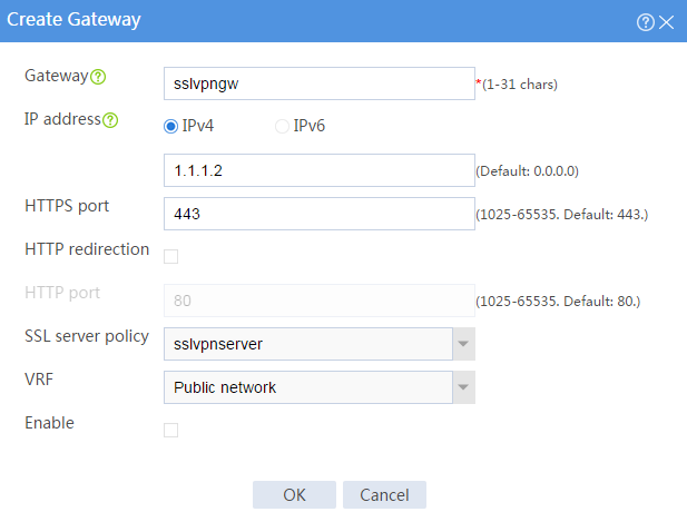
# Create an SSL VPN gateway as shown in Figure 2, and then click OK.
Figure 2 Creating an SSL VPN gateway
4. Configure an SSL VPN context:
# On the top navigation bar, click Network.
# From the navigation pane, select SSL VPN > SSL VPN Contexts.
# Click Create.
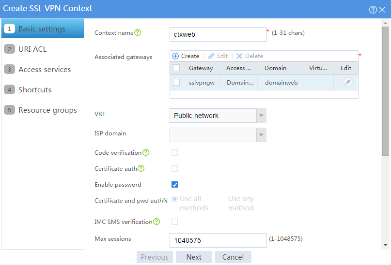
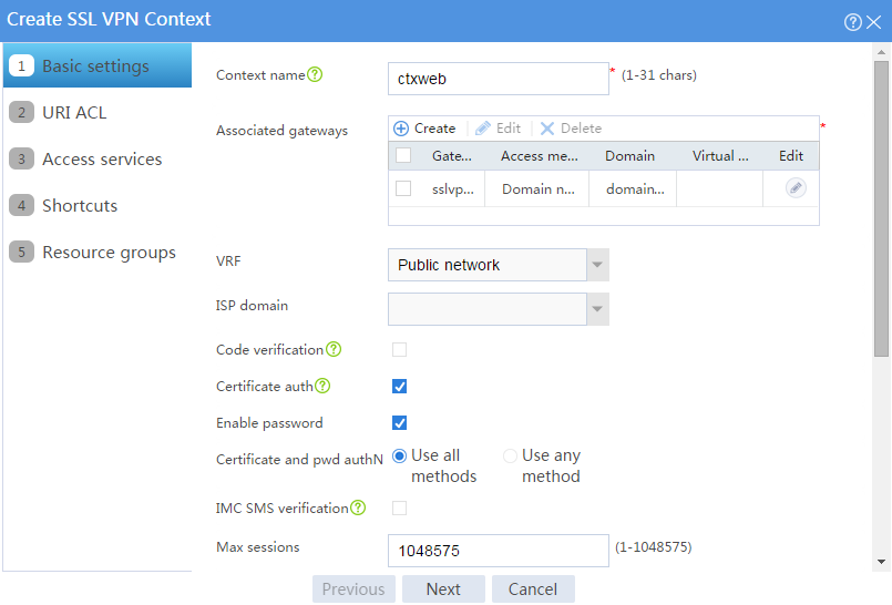
# Configure the basic settings for the SSL VPN context as shown in Figure 3, and then click Next.
Figure 3 Configuring basic settings for an SSL VPN context
# On the URI ACL page, click Next.
# On the Access services page, select Web access and click Next.
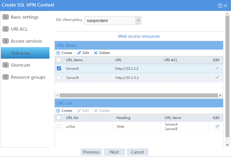
# On the Web access page, configure the Web access service as follows:
a. Configure two URL items pointing to Server A and Server B, respectively.
b. Add the two URL items to URL list urllist.
c. Click Next.
Figure 4 Configuring Web access service

# Click Next on the Shortcuts page.
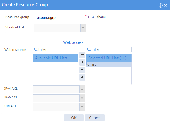
# On the Resource groups page, click Create.
# Create a resource group named resourcegrp and select URL list urllist as the accessible Web resources, as shown in Figure 5.
Figure 5 Creating an SSL VPN resource group
# Click OK.
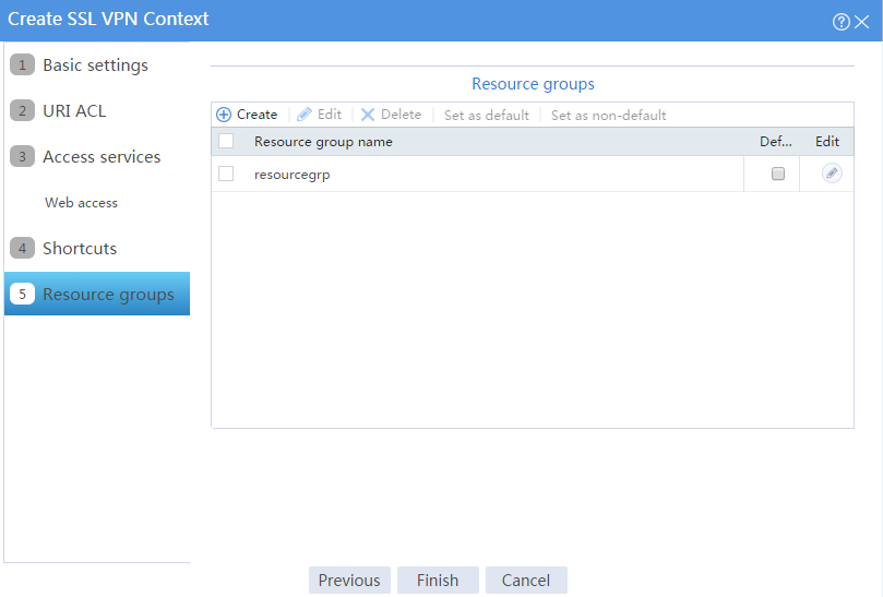
The newly created resource group is displayed on the Resource groups page, as shown in Figure 6.
Figure 6 Resource groups configuration page

# Click Finish.
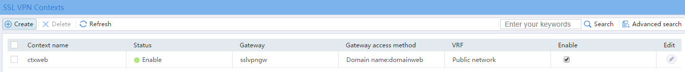
# Select the Enable check box to enable the SSL VPN context, as shown in Figure 7.
Figure 7 Enabling the SSL VPN context
5. Create an SSL VPN user:
# On the top navigation bar, click Objects.
# From the navigation pane, select User > User Management > Local Users.
# Click Create.
# Create an SSL VPN user:
a. Set the username to user1 and password to 123456, and select SSL VPN as the available service, as shown in Figure 8.
Figure 8 Creating an SSL VPN user

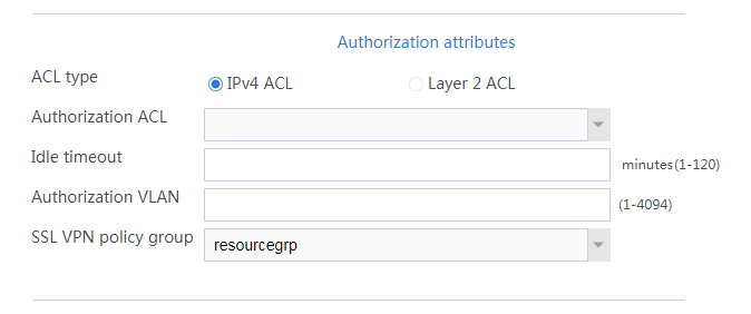
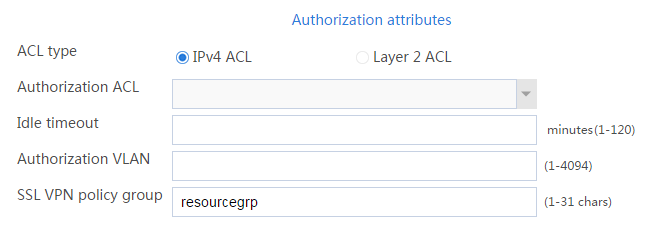
b. In the Authorization Attributes area, authorize the user to use SSL VPN resource group resourcegrp, as shown in Figure 9.
Figure 9 Setting the authorization attributes for the SSL VPN user
c. Click OK.
Configuring the host
# Configure the IP address and gateway address settings for the host and make sure it can reach the SSL VPN gateway.
Verifying the configuration
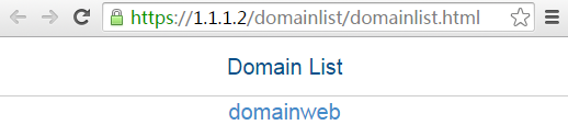
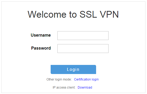
1. In the browser address bar of the host, enter https://1.1.1.2 and press Enter to open the domain list page.
Figure 10 Domain list page
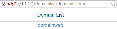
2. Select domainweb to access the login page.
3. On the login page, enter username user1 and password 123456, and then click Login.
Figure 11 Login page

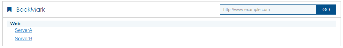
The SSL VPN home page opens, displaying the Web resources the user can access in the BookMark area.
Figure 12 Accessible Web resources
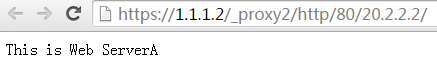
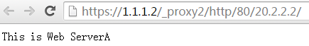
4. Click ServerA to access Web resources on Server A.
Figure 13 Accessing Server A
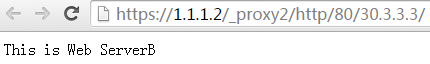
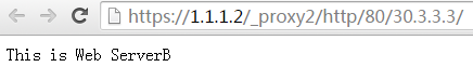
5. Click ServerB to access Web resources on Server B.
Figure 14 Accessing Server B
Network configuration
As shown in Figure 15, the device acts as the SSL VPN gateway that connects the public network and the private network. A Windows Server 2008 R2 CA server is deployed on the private network. Users need to access resources on internal Web servers Server A and Server B. Both Web servers use HTTP over port 80.
Configure the SSL VPN Web access service on the device to allow users to access Server A and Server B in Web access mode.
Configure the device to perform local authentication and authorization for Web access users. Require users to pass both password and certificate authentication for Web access. To enhance security, request an SSL server certificate for the device from the CA server rather than use the default certificate.
Software versions used
This configuration example was created and verified on E9345 of the F1060 device.
Procedure
Configuring the device
1. Assign IP addresses to interfaces and add the interfaces to security zones.
# On the top navigation bar, click the Network tab.
# From the navigation pane, select Interface Configuration > Interfaces.
# Click the Edit icon for GE 1/0/1.
# In the dialog box that opens, configure the interface:
a. On the Basic Configuration tab, select the Untrust security zone.
b. On the IPv4 Address tab, enter the IP address and mask length of the interface. In this example, enter 1.1.1.2/24.
c. Click OK.
# Add GE 1/0/2 to the Trust security zone and set its IP address to 3.3.3.3/24 in the same way you configure GE 1/0/1.
# Add GE 1/0/3 to the Trust security zone and set its IP address to 2.2.2.2/24 in the same way you configure GE 1/0/1.
2. Configure the security policy between the Trust and Untrust security zones. Make sure the Trust and Untrust security zones can communicate with each other.
3. Request a server certificate for the device:
a. Create a certificate subject:
# On the top navigation bar, click Objects.
# From the navigation pane, select PKI > Certificate Subject.
# Click Create.
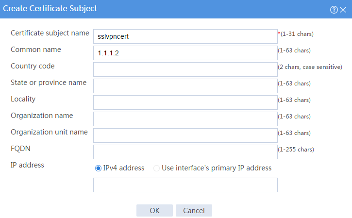
# Create a certificate subject as shown in Figure 16, and the click OK.
Figure 16 Creating a certificate subject

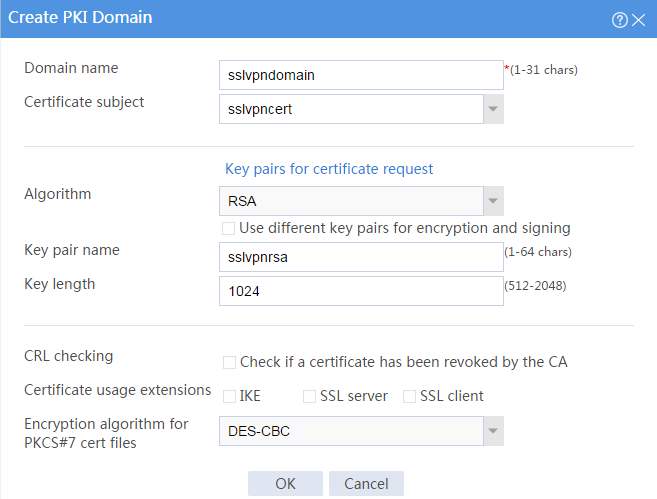
b. Create a PKI domain:
# On the Certificate page, click Create PKI domain.
# Create a PKI domain as shown in Figure 17, and then click OK.
Figure 17 Creating a PKI domain

c. Create a certificate request:
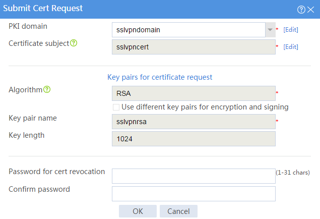
# On the Certificate page, click Submit Cert Request.
# Configure the certificate request settings as shown in Figure 18.
Figure 18 Creating a certificate request

# Click OK.
The certificate request content will be displayed, as shown in Figure 19.
Figure 19 Certificate request content

# Copy the certificate request content and click OK.
d. Request a server certificate from the CA:
# Enter http://192.168.100.247/certsrv in the browser address bar.
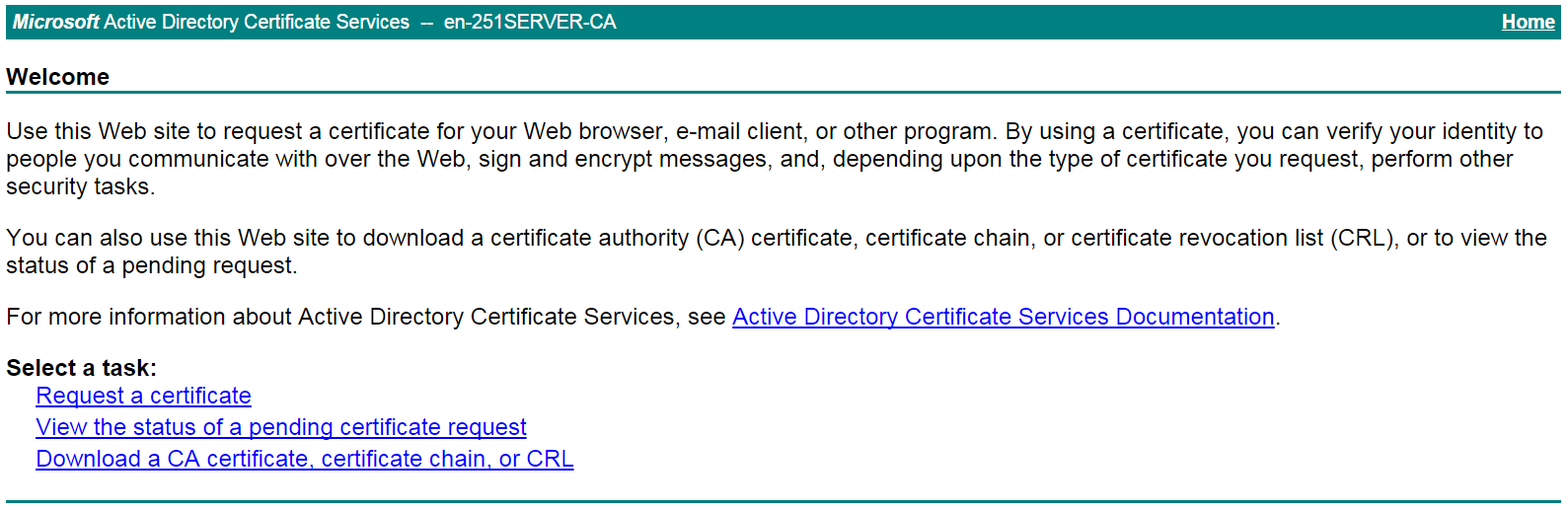
# On the certificate service home page shown in Figure 20, click Request a certificate.
Figure 20 Certificate service home page

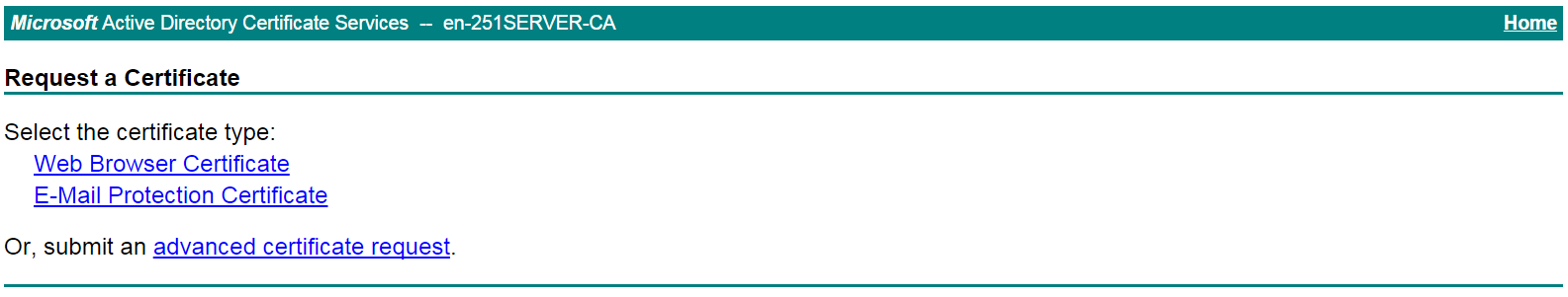
# On the Request a Certificate page shown in Figure 21, click advanced certificate request.
Figure 21 Request a Certificate page

# Paste the previously copied certificate request content in the Base-64-encoded certificate request CMC or PKCS # 10 or PKCS # 7) field, as shown in Figure 22.
Figure 22 Pasting the certificate request content

# Click Submit.
After the certificate request is approved by the CA administrator, enter http://192.168.100.247/certsrv in the browser address bar.
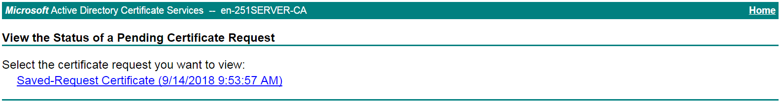
# On the certificate service home page shown in Figure 23, click View the status of a pending certificate request.
Figure 23 Certificate service home page

# Select the certificate request you want to view.
Figure 24 View the Status of a Pending Certificate Request page

The Certificate Issued page opens, indicating that the requested server certificate has been issued, as shown in Figure 25.
Figure 25 Certificate Issued page

# Click Download certificate to download the server certificate and save it locally.
4. Download the CA certificate:
# Enter http://192.168.100.247/certsrv in the browser address bar.
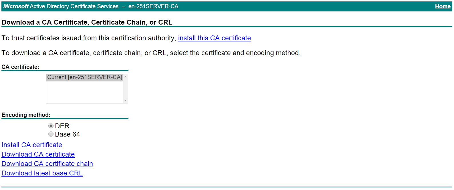
# On the certificate service home page shown in Figure 26, click Download a CA certificate, certificate chain, or CRL.
Figure 26 Certificate service home page
# On the Download a CA certificate, certificate chain, or CRL page shown in Figure 27, click Download CA certificate.
Figure 27 Download a CA certificate, certificate chain, or CRL page

# Save the downloaded CA certificate locally.
5. Import the CA certificate and server certificate to the PKI domain:
a. Import the CA certificate:
# On the top navigation bar, click Objects.
# From the navigation pane, select PKI > Certificate.
# Click Import certificate.
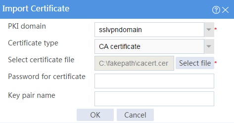
# Import the locally saved CA certificate, as shown in Figure 28, and then click OK.
Figure 28 Importing the CA certificate

b. Import the server certificate:
# On the Certificate page, click Import certificate.
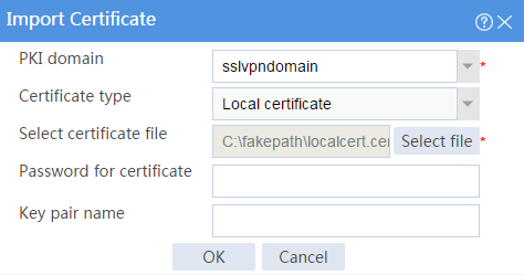
# Import the locally saved server certificate, as shown in Figure 29, and then click OK.
Figure 29 Importing the server certificate

6. Configure an SSL server policy:
# On the top navigation bar, click Objects.
# From the navigation pane, select SSL > SSL Server Policies.
# Click Create.
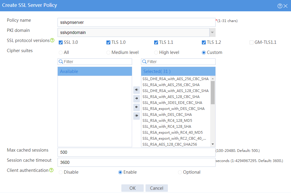
# Configure an SSL server policy as shown in Figure 30, and then click OK.
Figure 30 Creating an SSL server policy

7. Configure an SSL client policy:
# On the top navigation bar, click Objects.
# From the navigation pane, select SSL > SSL Client Policies.
# Click Create.
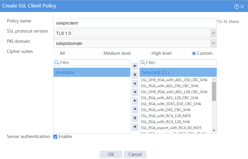
# Configure an SSL client policy as shown in Figure 31, and then click OK.
Figure 31 Creating an SSL client policy

8. Configure the SSL VPN gateway:
# On the top navigation bar, click Network.
# From the navigation pane, select SSL VPN > SSL VPN Gateways.
# Click Create.
# Create an SSL VPN gateway as shown in Figure 32, and then click OK.
Figure 32 Creating an SSL VPN gateway
9. Configure an SSL VPN context:
# On the top navigation bar, click Network.
# From the navigation pane, select SSL VPN > SSL VPN Contexts.
# Click Create.
# Configure the basic settings for the SSL VPN context as shown in Figure 3, and then click Next.
Figure 33 Configuring basic settings for an SSL VPN context
# On the URI ACL page, click Next.
# On the Access services page, select Web access and click Next.
# On the Web access page, configure the Web access service as follows:
a. Select sslvpnclient from the SSL client policy list.
b. Configure two URL items pointing to Server A and Server B, respectively.
c. Add the two URL items to URL list urllist.
d. Click Next.
Figure 34 Configuring the Web access service
# Click Next on the Shortcuts page.
# On the Resource groups page, click Create.
# Create a resource group named resourcegrp and select URL list urllist as the accessible Web resources, as shown in Figure 35.
# Click OK.
Figure 35 Creating an SSL VPN resource group

The newly created resource group is displayed on the Resource groups page, as shown in Figure 36.
Figure 36 Resource groups configuration page
# Click Finish.
# Select the Enable check box to enable the SSL VPN context, as shown in Figure 37.
Figure 37 Enabling the SSL VPN context

10. Create an SSL VPN user:
# On the top navigation bar, click Objects.
# From the navigation pane, select User > User Management > Local Users.
# Click Create.
# Create an SSL VPN user:
a. Set the username to user1 and password to 123456, and select SSL VPN as the available service, as shown in Figure 38.
Figure 38 Creating an SSL VPN user

b. In the Authorization Attributes area, authorize the user to use SSL VPN resource group resourcegrp, as shown in Figure 39.
Figure 39 Setting the authorization attributes for the SSL VPN user
c. Click OK.
Configuring the host
1. Configure the IP address and gateway address settings for the host and make sure it can reach the SSL VPN gateway and the CA server.
2. Submit a client certificate request to the CA server:
a. Enter http://192.168.100.247/certsrv in the browser address bar.
b. On the certificate service home page shown in Figure 40, click Request a certificate.
Figure 40 Certificate service home page

c. On the Request a Certificate page shown in Figure 41, click advanced certificate request.
Figure 41 Request a Certificate page
d. Create a client certificate request, as shown in Figure 42.
Figure 42 Creating a client certificate request

e. Click Submit.
3. Install the client certificate on the host:
a. After the certificate request is approved by the CA administrator, enter http://192.168.100.247/certsrv in the browser address bar.
b. On the certificate service home page shown in Figure 43, click View the status of a pending certificate request.
Figure 43 Certificate service home page

The View the Status of a Pending Certificate Request page opens, as shown in Figure 44.
Figure 44 View the Status of a Pending Certificate Request page

c. Click the client certificate whose status you want to view.
d. On the Certificate Issued page shown in Figure 45, click Install this certificate to install the client certificate.
Figure 45 Installing the client certificate

If the host does not have a CA certificate, the page shown in Figure 46 opens. You must install the CA certificate first.
e. Click install this CA certificate to install the CA certificate. Then, click Install this certificate to install the client certificate.
Figure 46 Installing the CA certificate and then the client certificate

After the client certificate is installed, the Certificate Installed page shown in Figure 47 opens.
Figure 47 Certificate Installed page

Verifying the configuration
1. In the browser address bar of the host, enter https://1.1.1.2 and press Enter.
2. On the Select a certificate page, select the client certificate for authentication, as shown in Figure 48.
Figure 48 Select a certificate page

3. Click OK.
4. On the Domain List page shown in Figure 49, click domainweb.
5. On the SSL VPN login page shown in Figure 50, enter username user1 and password and 123456, and then click Login
The SSL VPN home page opens, displaying the Web resources the user can access in the BookMark area, as shown in Figure 51.
Figure 51 Accessible Web resources

6. Click ServerA to access Web resources on Server A.
7. Click ServerB to access Web resources on Server B.
Figure 53 Accessing Server B
Network configuration
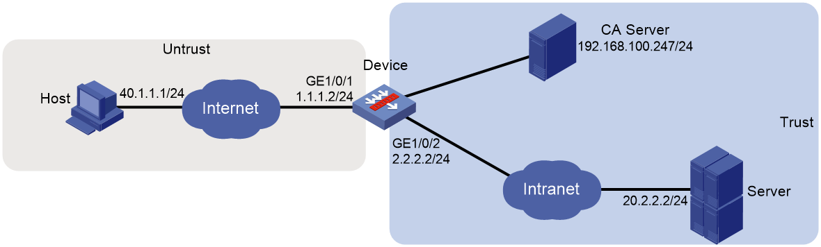
As shown in Figure 54, the device acts as the SSL VPN gateway that connects the public network and the private network. Users need secure access to the internal Telnet server in TCP access mode.
Configure the SSL VPN TCP access service on the device to allow users to access the server in TCP access mode.
Configure the device to perform local authentication and authorization for TCP access users.
The device uses a self-signed SSL server certificate.
Software versions used
This configuration example was created and verified on E9345 of the F1060 device.
Restrictions and guidelines
When you configure TCP access with a self-signed server certificate, follow these restrictions and guidelines:
· Certificate-based client authentication is not available in TCP access mode.
· To start the TCP client from the Web interface, make sure the Java Runtime Environment is installed on the client host.
· To access internal resources in TCP access mode from the host, modifications to the Hosts file on the host might be required. Make sure you log in to the host with administrative privileges.
Procedure
Configuring the device
1. Assign IP addresses to interfaces and add the interfaces to security zones.
# On the top navigation bar, click the Network tab.
# From the navigation pane, select Interface Configuration > Interfaces.
# Click the Edit icon for GE 1/0/1.
# In the dialog box that opens, configure the interface:
a. On the Basic Configuration tab, select the Untrust security zone.
b. On the IPv4 Address tab, enter the IP address and mask length of the interface. In this example, enter 1.1.1.2/24.
c. Click OK.
# Add GE 1/0/2 to the Trust security zone and set its IP address to 2.2.2.2/24 in the same way you configure GE 1/0/1.
2. Configure the security policy between the Trust and Untrust security zones. Make sure the Trust and Untrust security zones can communicate with each other.
3. Configure the SSL VPN gateway:
# On the top navigation bar, click Network.
# From the navigation pane, select SSL VPN > SSL VPN Gateways.
# Click Create.
# Create an SSL VPN gateway as shown in Figure 55, and then click OK.
Figure 55 Creating an SSL VPN gateway

4. Configure an SSL VPN context:
# On the top navigation bar, click Network.
# From the navigation pane, select SSL VPN > SSL VPN Contexts.
# Click Create.
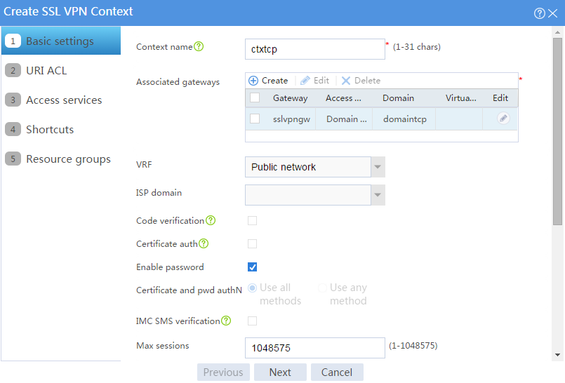
# Configure the basic settings for the SSL VPN context as shown in Figure 56, and then click Next.
Figure 56 Creating an SSL VPN context

# On the URI ACL page, click Next.
# On the Access services page, select TCP access and click Next.
# On the TCP access page, click Create in the Port Forwarding Item area.
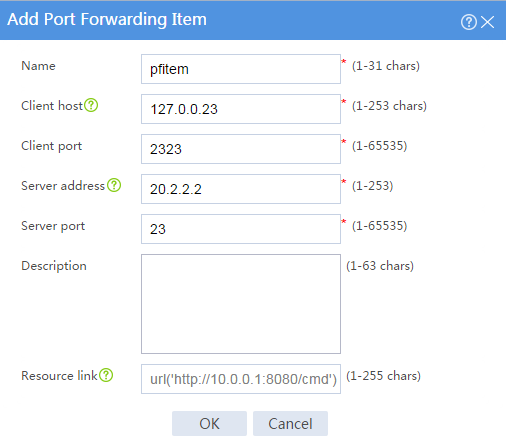
# Create a port forwarding item named pfitem as shown in Figure 57, and then click OK.
Figure 57 Creating a port forwarding item

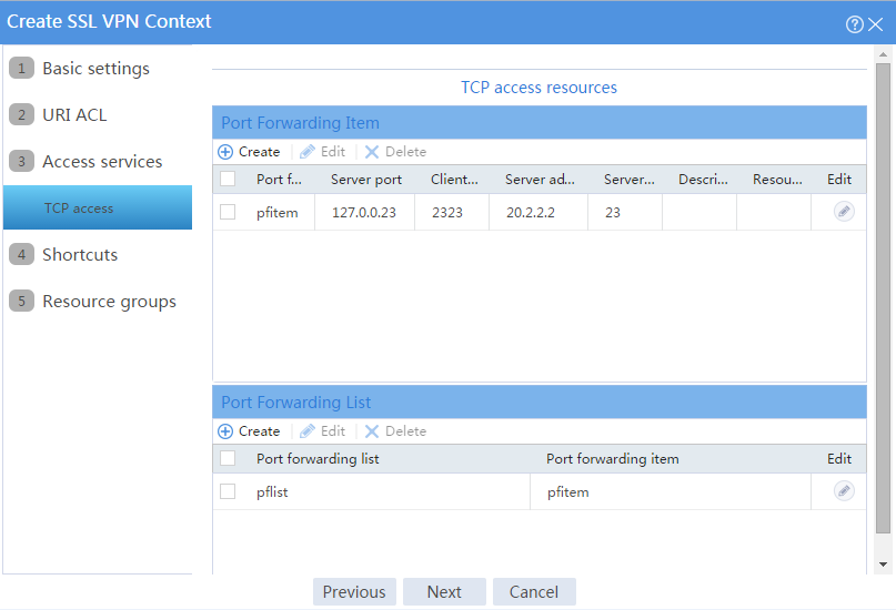
# Click Create in the Port Forwarding List area.
# Create a port forwarding list named pflist and assign port forwarding item pfitem to it, as shown in Figure 58.
Figure 58 Configuring TCP access resources

# Click Next on the Shortcuts page.
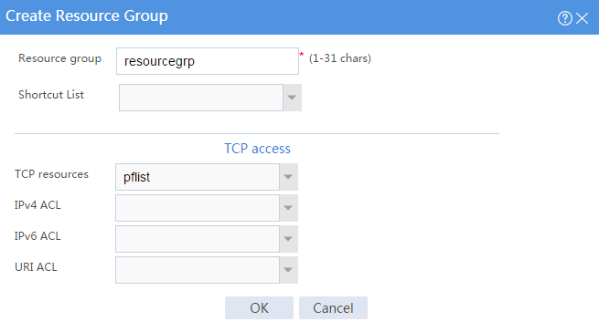
# On the Resource groups page, click Create.
# Create a resource group named resourcegrp and select port forwarding list pflist from the TCP resources list, as shown in Figure 59.
Figure 59 Creating an SSL VPN resource group
# Click OK.
The newly created resource group is displayed on the Resource groups page, as shown in Figure 60.
Figure 60 Resource groups configuration page

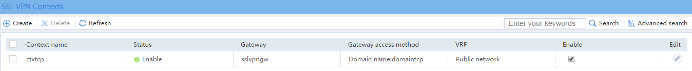
# Click Finish.
# Select the Enable check box to enable the SSL VPN context, as shown in Figure 61.
Figure 61 Enabling the SSL VPN context
5. Create an SSL VPN user:
# On the top navigation bar, click Objects.
# From the navigation pane, select User > User Management > Local Users.
# Click Create.
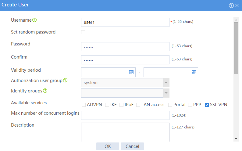
# Create an SSL VPN user:
a. Set the username to user1 and password to 123456, and select SSL VPN as the available service, as shown in Figure 62.
Figure 62 Creating an SSL VPN user

b. In the Authorization Attributes area, authorize the user to use SSL VPN resource group resourcegrp, as shown in Figure 63.
Figure 63 Setting the authorization attributes for the SSL VPN user

c. Click OK.
Configuring the host
# Configure the IP address and gateway address settings for the host and make sure it can reach the SSL VPN gateway.
Verifying the configuration
1. In the browser address bar of the host, enter https://1.1.1.2 and press Enter to open the domain list page.
Figure 64 Domain list page
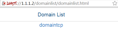
2. Select domaintcp to access the login page.
3. On the login page, enter username user1 and password 123456, and then click Login.
Figure 65 Login page

The SSL VPN home page opens, displaying the TCP resources the user can access in the TCP Resource area.
Figure 66 Accessible TCP resources

4. Click START to start the TCP client application.
You cannot start the TCP client application by double-clicking it..
5. Telnet to local address 127.0.0.1 and local port 2323 to access the server.
Example: Configuring TCP access with a CA-signed server certificate
Network configuration
As shown in Figure 67, the device acts as the SSL VPN gateway that connects the public network and the private network. A Windows Server 2008 R2 CA server is deployed on the private network. Users need secure access to the internal Telnet server in TCP access mode.
Perform the following tasks:
· Request a server certificate for the device from the CA server.
· Configure the SSL VPN TCP access service on the device to allow users to access the server in TCP access mode.
· Configure the device to perform local authentication and authorization for TCP access users.
Software versions used
This configuration example was created and verified on E9345 of the F1060 device.
Restrictions and guidelines
· Certificate-based client authentication is not available in TCP access mode.
· To start the TCP client from the Web interface, make sure the Java Runtime Environment is installed on the client host.
· To access internal resources in TCP access mode from the host, modifications to the Hosts file on the host might be required. Make sure you log in to the host with administrative privileges.
Procedure
Configuring the device
1. Assign IP addresses to interfaces and add the interfaces to security zones.
# On the top navigation bar, click the Network tab.
# From the navigation pane, select Interface Configuration > Interfaces.
# Click the Edit icon for GE 1/0/1.
# In the dialog box that opens, configure the interface:
a. On the Basic Configuration tab, select the Untrust security zone.
b. On the IPv4 Address tab, enter the IP address and mask length of the interface. In this example, enter 1.1.1.2/24.
c. Click OK.
# Add GE 1/0/2 to the Trust security zone and set its IP address to 2.2.2.2/24 in the same way you configure GE 1/0/1.
2. Configure the security policy between the Trust and Untrust security zones. Make sure the Trust and Untrust security zones can communicate with each other.
3. Request a server certificate for the device:
a. Create a certificate subject:
# On the top navigation bar, click Objects.
# From the navigation pane, select PKI > Certificate Subject.
# Click Create.
# Create a certificate subject as shown in Figure 68, and the click OK.
Figure 68 Creating a certificate subject
b. Create a PKI domain:
# On the top navigation bar, click Objects.
# From the navigation pane, select PKI > Certificate.
# Click Create PKI domain.
# Create a PKI domain as shown in Figure 69, and then click OK.
Figure 69 Creating a PKI domain

c. Create a certificate request:
# On the Certificate page, click Submit Cert Request.
# Configure the certificate request settings as shown in Figure 70.
Figure 70 Creating a certificate request

# Click OK.
The certificate request content will be displayed, as shown in Figure 71.
Figure 71 Certificate request content

# Copy the certificate request content and click OK.
d. Request a server certificate from the CA:
# Enter http://192.168.100.247/certsrv in the browser address bar.
# On the certificate service home page shown in Figure 72, click Request a certificate.
Figure 72 Certificate service home page

# On the Request a Certificate page shown in Figure 73, click advanced certificate request.
Figure 73 Request a Certificate page

# Paste the previously copied certificate request content in the Base-64-encoded certificate request CMC or PKCS # 10 or PKCS # 7) field, as shown in Figure 74.
Figure 74 Pasting the certificate request content
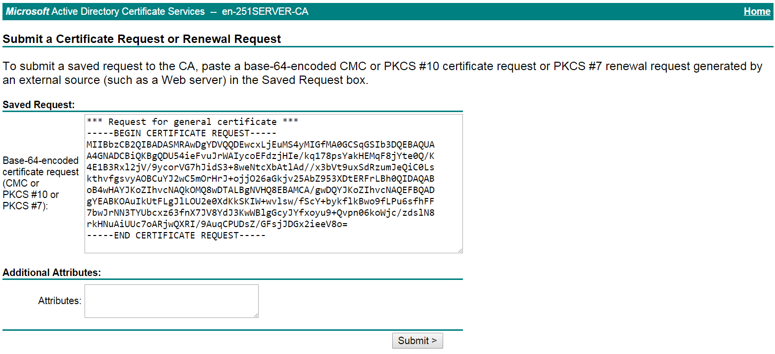
# Click Submit.
After the certificate request is approved by the CA administrator, enter http://192.168.100.247/certsrv in the browser address bar.
# On the certificate service home page shown in Figure 75, click View the status of a pending certificate request.
Figure 75 Certificate service home page

# Select the certificate request you want to view. In this example, select Saved-Request Certificate (9/24/2018 9:53:57 AM), as shown in Figure 76.
Figure 76 View the Status of a Pending Certificate Request page

The Certificate Issued page opens, indicating that the requested server certificate has been issued, as shown in Figure 77.
Figure 77 Certificate Issued page

# Click Download certificate to download the server certificate and save it locally.
4. Download the CA certificate:
# Enter http://192.168.100.247/certsrv in the browser address bar.
# On the certificate service home page shown in Figure 78, click Download a CA certificate, certificate chain, or CRL.
Figure 78 Certificate service home page

# On the Download a CA certificate, certificate chain, or CRL page, click Download CA certificate.
Figure 79 Download a CA certificate, certificate chain, or CRL page

# Save the downloaded CA certificate locally.
5. Import the CA and server certificates:
a. Import the CA certificate:
# On the top navigation bar, click Objects.
# From the navigation pane, select PKI > Certificate.
# Click Import certificate.
# Import the locally saved CA certificate, as shown in Figure 80, and then click OK.
Figure 80 Importing the CA certificate

b. Import the server certificate:
# On the Certificate page, click Import certificate.
# Import the locally saved server certificate, as shown in Figure 81, and then click OK.
Figure 81 Importing the server certificate

6. Configure an SSL server policy:
# On the top navigation bar, click Objects.
# From the navigation pane, select SSL > SSL Server Policies.
# Click Create.
# Configure an SSL server policy as shown in Figure 82, and then click OK.
Figure 82 Creating an SSL server policy

7. Configure the SSL VPN gateway:
# On the top navigation bar, click Network.
# From the navigation pane, select SSL VPN > SSL VPN Gateways.
# Click Create.
# Create an SSL VPN gateway as shown in Figure 83, and then click OK.
Figure 83 Creating an SSL VPN gateway

8. Configure an SSL VPN context:
# On the top navigation bar, click Network.
# From the navigation pane, select SSL VPN > SSL VPN Contexts.
# Click Create.
# Configure the basic settings for the SSL VPN context as shown in Figure 84, and then click Next.
Figure 84 Creating an SSL VPN context
# On the URI ACL page, click Next.
# On the Access services page, select TCP access and click Next.
# On the TCP access page, click Create in the Port Forwarding Item area.
# Create a port forwarding item named pfitem as shown in Figure 85, and then click OK.
Figure 85 Creating a port forwarding item
# Create a port forwarding list named pflist and assign port forwarding item pfitem to it, as shown in Figure 86.
Figure 86 Configuring TCP access resources
# Click Next on the Shortcuts page.
# On the Resource groups page, click Create.
# Create a resource group named resourcegrp and select port forwarding list pflist from the TCP resources list, as shown in Figure 87.
Figure 87 Creating an SSL VPN resource group

# Click OK.
The newly created resource group is displayed on the Resource groups page, as shown in Figure 88.
Figure 88 Resource groups configuration page

# Click Finish.
# Select the Enable check box to enable the SSL VPN context, as shown in Figure 89.
Figure 89 Enabling the SSL VPN context

9. Create an SSL VPN user:
# On the top navigation bar, click Objects.
# From the navigation pane, select User > User Management > Local Users.
# Click Create.
# Create an SSL VPN user:
a. Set the username to user1 and password to 123456, and select SSL VPN as the available service, as shown in Figure 90.
Figure 90 Creating an SSL VPN user
b. In the Authorization Attributes area, authorize the user to use SSL VPN resource group resourcegrp, as shown in Figure 91.
Figure 91 Setting the authorization attributes for the SSL VPN user

c. Click OK.
Configuring the host
# Configure the IP address and gateway address settings for the host and make sure it can reach the SSL VPN gateway.
Verifying the configuration
1. In the browser address bar of the host, enter https://1.1.1.2 and press Enter to open the domain list page.
Figure 92 Domain list page

2. Select domaintcp to access the login page.
3. On the login page, enter username user1 and password 123456, and then click Login.
Figure 93 Login page

The SSL VPN home page opens, displaying the TCP resources the user can access in the TCP Resource area.
Figure 94 Accessible TCP resources

4. Click START to start the TCP client application.
You cannot start the TCP client application by double-clicking it.
5. Telnet to local address 127.0.0.1 and local port 2323 to access the server.
Network configuration
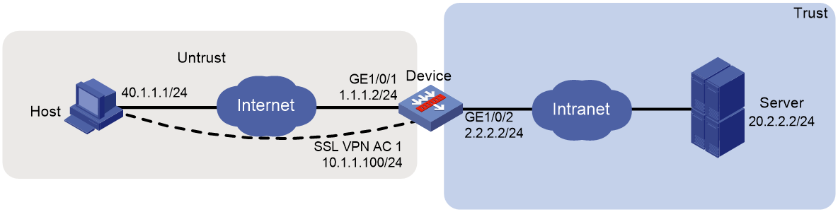
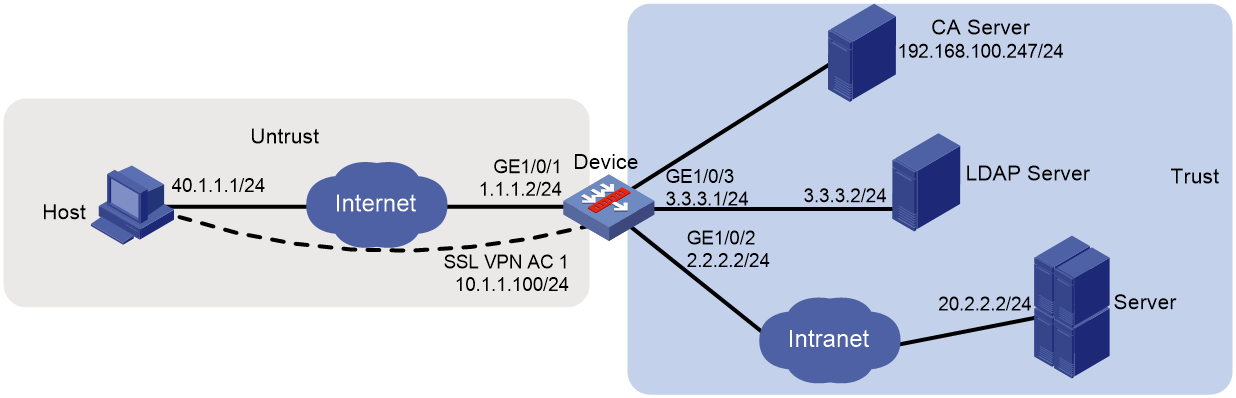
As shown in Figure 95, the device acts as an SSL VPN gateway that connects the public network and the private network. Users need secure access to the internal server in IP access mode.
The device uses a self-signed server certificate.
Perform the following tasks:
· Configure the SSL VPN IP access service on the device to allow users to access the internal server in IP access mode.
· Configure the device to perform local authentication and authorization for IP access users.
Software versions used
This configuration example was created and verified on E9345 of the F1060 device.
Restrictions and guidelines
· The IP address pool configured for client address allocation must meet the following requirements:
¡ The address range of the address pool cannot be on the same subnet as the IP address used on the client host.
¡ The IP addresses in the address pool do not conflict with the IP addresses used on the device.
¡ The address range of the address pool cannot be on the same subnet as the IP address of the internal server.
· The SSL VPN AC interface must be added to the correct security zone (Untrust, in this example).
Procedure
Configuring the device
1. Assign IP addresses to interfaces and add the interfaces to security zones.
# On the top navigation bar, click the Network tab.
# From the navigation pane, select Interface Configuration > Interfaces.
# Click the Edit icon for GE 1/0/1.
# In the dialog box that opens, configure the interface:
a. On the Basic Configuration tab, select the Untrust security zone.
b. On the IPv4 Address tab, enter the IP address and mask length of the interface. In this example, enter 1.1.1.2/24.
c. Click OK.
# Add GE 1/0/2 to the Trust security zone and set its IP address to 2.2.2.2/24 in the same way you configure GE 1/0/1.
# Add GE 1/0/3 to the Trust security zone and set its IP address to 3.3.3.1/24 in the same way you configure GE 1/0/1.
2. Configure the security policy between the Trust and Untrust security zones. Make sure the Trust and Untrust security zones can communicate with each other.
3. Configure the SSL VPN gateway:
# On the top navigation bar, click Network.
# From the navigation pane, select SSL VPN > SSL VPN Gateways.
# Click Create.
# Create an SSL VPN gateway as shown in Figure 96, and then click OK.
Figure 96 Creating an SSL VPN gateway

4. Create an SSL VPN AC interface:
# On the top navigation bar, click Network.
# From the navigation pane, select SSL VPN > SSL VPN AC Interfaces.
# Click Create.
# In the Create Interfaces dialog box that opens, enter 1 in the Interface number field and click OK.
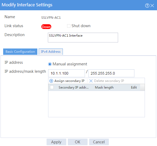
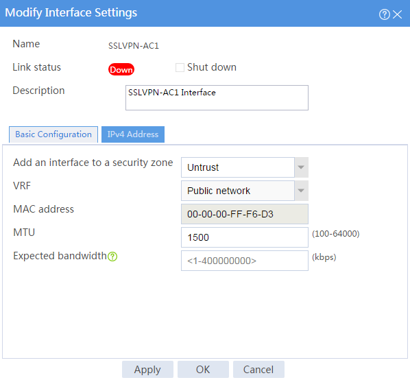
# In the Modify Interface Settings dialog box, configure the basic settings for the SSL VPN AC interface as shown in Figure 97.
Figure 97 Configuring basic settings for the SSL VPN AC interface

# Click the IPv4 Address tab and configure the IPv4 address settings for the SSL VPN AC interface as shown in Figure 98.
# Click OK.
Figure 98 Configuring IPv4 address settings for the SSL VPN AC interface

5. Create an address pool for IP access users:
# On the top navigation bar, click Network.
# From the navigation pane, select SSL VPN > IP Access Address Pools.
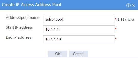
# Click Create.
# Create an IP access address pool as shown in Figure 99, and then click OK.
Figure 99 Creating an IP access address pool

6. Configure an SSL VPN context:
# On the top navigation bar, click Network.
# From the navigation pane, select SSL VPN > SSL VPN Contexts.
# Click Create.
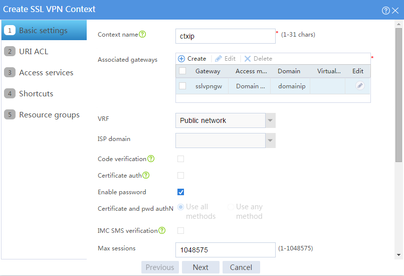
# Configure the basic settings for the SSL VPN context as shown in Figure 100, and then click Next.
Figure 100 Configuring basic settings for an SSL VPN context
# On the URI ACL page, click Next.
# On the Access services page, select IP access and click Next.
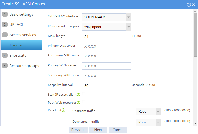
# On the IP access page, configure the IP access service as follows:
a. Configure the IP access parameters as shown in Figure 101 and click Next.
Figure 101 Configuring IP access parameters for the IP access service

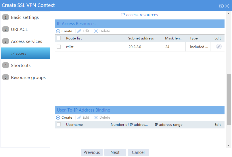
b. In the IP access resources area, configure route list rtlist with an included route entry for 20.2.2.0/24, as shown in Figure 102.
c. Click Next.
Figure 102 Configuring IP access resources for the IP access service
# Click Next on the Shortcuts page.
# On the Resource groups page, click Create.
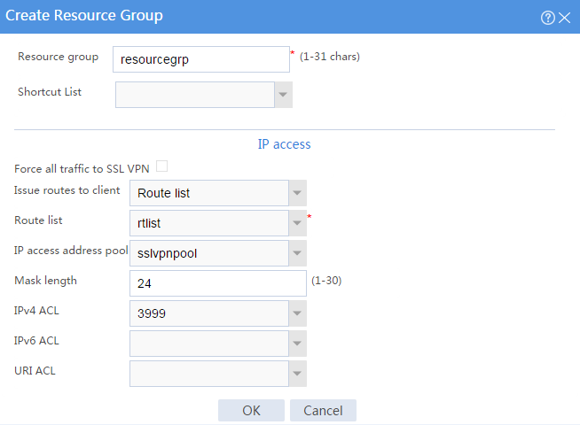
# Create a resource group named resourcegrp, as shown in Figure 103. In this example, select route list rtlist as the accessible IP resources and use IPv4 ACL 3999 (which permits all traffic) for IP access request filtering.
Figure 103 Creating an SSL VPN resource group
# Click OK.
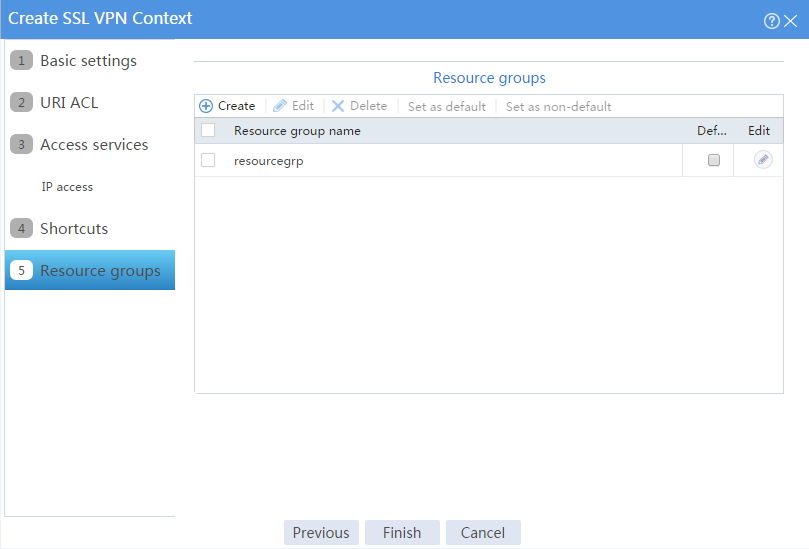
The newly created resource group is displayed on the Resource groups page, as shown in Figure 104.
Figure 104 Resource groups configuration page
# Click Finish.
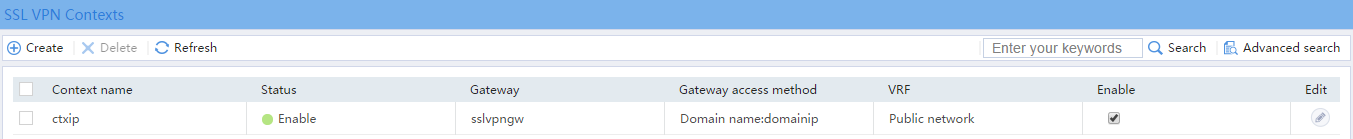
# Select the Enable check box to enable the SSL VPN context, as shown in Figure 105.
Figure 105 Enabling the SSL VPN context
7. Create an SSL VPN user:
# On the top navigation bar, click Objects.
# From the navigation pane, select User > User Management > Local Users.
# Click Create.
# Create an SSL VPN user:
a. Set the username to user1 and password to 123456, and select SSL VPN as the available service, as shown in Figure 106.
Figure 106 Creating an SSL VPN user

b. In the Authorization Attributes area, authorize the user to use SSL VPN resource group resourcegrp, as shown in Figure 107.
Figure 107 Setting the authorization attributes for the SSL VPN user

c. Click OK.
Configuring the host
# Configure the IP address and gateway address settings for the host and make sure it can reach the SSL VPN gateway.
Verifying the configuration
1. In the browser address bar of the host, enter https://1.1.1.2 and press Enter to open the domain list page.
Figure 108 Domain list page
2. Select domainip to access the login page.
3. On the login page, enter username user1 and password 123456, and then click Login.
Figure 109 Login page

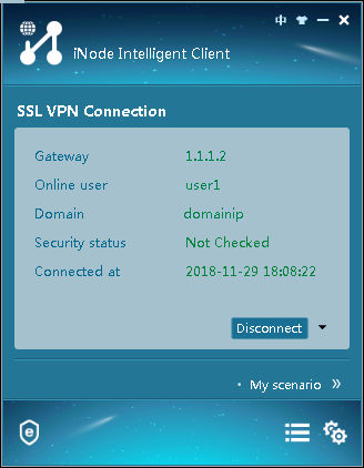
4. Click START to start the IP client application.
If the host does not have an iNode client installed, the system installs the iNode client and connects the iNode client to the SSL VPN gateway.
If the host already has an iNode client installed, the system starts the iNode client and connects it to the SSL VPN gateway directly.
Figure 110 shows that the iNode client is successfully connected to the SSL VPN gateway.
Figure 110 Connecting the iNode client to the SSL VPN gateway

Network configuration
As shown in Figure 111, the device acts as an SSL VPN gateway that connects the public network and the private network. On the private network, a Windows Server 2008 R2 CA server and a RADIUS server that runs IMC PLAT 7.3 (E0504) are deployed. Users need secure access to the internal server (20.2.2.2/24) in IP access mode.
Perform the following tasks:
· Request an SSL server certificate for the device from the CA server.
· Configure the device to require that users pass certificate authentication for IP access.
· Configure the device to use the RADIUS server to perform remote authentication and authorization for IP access users.
· Configure the SSL VPN IP access service on the device to allow users to access the internal server in IP access mode.

Software versions used
This configuration example was created and verified on E9345 of the F1060 device.
Restrictions and guidelines
· The IP address pool configured for client address allocation must meet the following requirements:
¡ The address range of the address pool cannot be on the same subnet as the IP address used on the client host.
¡ The IP addresses in the address pool do not conflict with the IP addresses used on the device.
¡ The address range of the address pool cannot be on the same subnet as the IP address of the internal server.
· The SSL VPN AC interface must be added to the correct security zone (Untrust, in this example).
Procedure
Configuring the device
1. Assign IP addresses to interfaces and add the interfaces to security zones.
# On the top navigation bar, click the Network tab.
# From the navigation pane, select Interface Configuration > Interfaces.
# Click the Edit icon for GE 1/0/1.
# In the dialog box that opens, configure the interface:
a. On the Basic Configuration tab, select the Untrust security zone.
b. On the IPv4 Address tab, enter the IP address and mask length of the interface. In this example, enter 1.1.1.2/24.
c. Click OK.
# Add GE 1/0/2 to the Trust security zone and set its IP address to 2.2.2.2/24 in the same way you configure GE 1/0/1.
# Add GE 1/0/3 to the Trust security zone and set its IP address to 3.3.3.1/24 in the same way you configure GE 1/0/1.
2. Configure the security policy between the Trust and Untrust security zones. Make sure the Trust and Untrust security zones can communicate with each other.
3. Request a server certificate for the device:
a. Create a certificate subject:
# On the top navigation bar, click Objects.
# From the navigation pane, select PKI > Certificate Subject.
# Click Create.
# Create a certificate subject as shown in Figure 112, and the click OK.
Figure 112 Creating a certificate subject

b. Create a PKI domain:
# On the Certificate page, click Create PKI domain.
# Create a PKI domain as shown in Figure 113, and then click OK.
Figure 113 Creating a PKI domain

c. Create a certificate request:
# On the Certificate page, click Submit Cert Request.
# Configure the certificate request settings as shown in Figure 114.
Figure 114 Creating a certificate request
# Click OK.
The certificate request content will be displayed, as shown in Figure 115.
Figure 115 Certificate request content

# Copy the certificate request content and click OK.
d. Request a server certificate from the CA:
# Enter http://192.168.100.247/certsrv in the browser address bar.
# On the certificate service home page shown in Figure 116, click Request a certificate.
Figure 116 Certificate service home page

# On the Request a Certificate page shown in Figure 117, click advanced certificate request.
Figure 117 Request a Certificate page

# Paste the previously copied certificate request content in the Base-64-encoded certificate request CMC or PKCS # 10 or PKCS # 7) field, as shown in Figure 118.
Figure 118 Pasting the certificate request content

# Click Submit.
After the certificate request is approved by the CA administrator, enter http://192.168.100.247/certsrv in the browser address bar.
# On the certificate service home page shown in Figure 119, click View the status of a pending certificate request.
Figure 119 Certificate service home page

# Select the certificate request you want to view.
Figure 120 View the Status of a Pending Certificate Request page
The Certificate Issued page opens, indicating that the requested server certificate has been issued, as shown in Figure 121.
Figure 121 Certificate Issued page

# Click Download certificate to download the server certificate and save it locally.
4. Download the CA certificate:
# Enter http://192.168.100.247/certsrv in the browser address bar.
# On the certificate service home page shown in Figure 122, click Download a CA certificate, certificate chain, or CRL.
Figure 122 Certificate service home page

# On the Download a CA certificate, certificate chain, or CRL page shown in Figure 123, click Download CA certificate.
Figure 123 Download a CA certificate, certificate chain, or CRL page
# Save the downloaded CA certificate locally.
5. Import the CA certificate and server certificate to the PKI domain:
a. Import the CA certificate:
# On the top navigation bar, click Objects.
# From the navigation pane, select PKI > Certificate.
# Click Import certificate.
# Import the locally saved CA certificate, as shown in Figure 124, and then click OK.
Figure 124 Importing the CA certificate
b. Import the server certificate:
# On the Certificate page, click Import certificate.
# Import the locally saved server certificate, as shown in Figure 125, and then click OK.
Figure 125 Importing the server certificate

6. Configure an SSL server policy:
# On the top navigation bar, click Objects.
# From the navigation pane, select SSL > SSL Server Policies.
# Click Create.
# Configure an SSL server policy as shown in Figure 126, and then click OK.
Figure 126 Creating an SSL server policy

7. Configure an SSL client policy:
# On the top navigation bar, click Objects.
# From the navigation pane, select SSL > SSL Client Policies.
# Click Create.
# Configure an SSL client policy as shown in Figure 127, and then click OK.
Figure 127 Creating an SSL client policy
8. Configure a RADIUS scheme:
# On the top navigation bar, click Objects.
# From the navigation pane, select User > Authentication > RADIUS.
# Click Create.
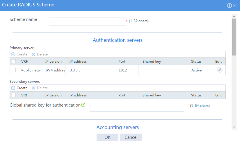
# Configure a RADIUS scheme named radius:
¡ Set the authentication server as shown in Figure 128.
¡ Set the global shared key for authentication to 123456.
Figure 128 Configuring a RADIUS scheme
# Configure the advanced settings for the RADIUS scheme in the Advanced settings area, as shown in Figure 129.
Figure 129 Configuring the advanced settings for the RADIUS scheme
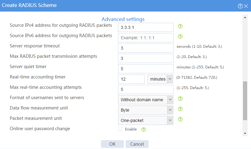
# Click OK.
9. At the CLI, create ISP domain sslvpn, specify RADIUS scheme radius for the authentication and authorization methods, and set the accounting method to none.
<Device> system-view
[Device] domain sslvpn
[Device-isp-sslvpn] authentication sslvpn radius-scheme radius
[Device-isp-sslvpn] authorization sslvpn radius-scheme radius
[Device-isp-sslvpn] accounting sslvpn none
[Device-isp-sslvpn] quit
10. Create a user group:
# On the top navigation bar, click Objects.
# From the navigation pane, select User > User Management > Local Users.
# Click the User Group tab.
# Click Create.
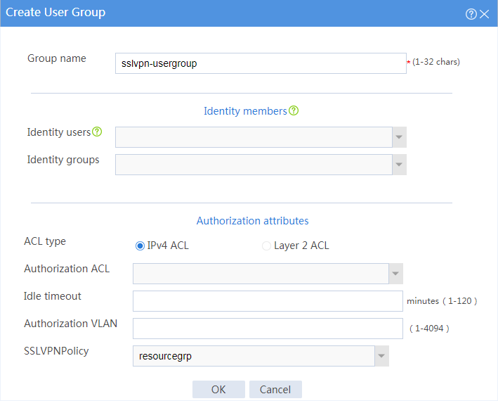
# Create a user group named sslvpn_usergroup and specify SSL VPN resource group resourcegrp for the user group, as shown in Figure 130.
# Click OK.
Figure 130 Creating a user group

11. Configure the SSL VPN gateway:
# On the top navigation bar, click Network.
# From the navigation pane, select SSL VPN > SSL VPN Gateways.
# Click Create.
# Create an SSL VPN gateway as shown in Figure 131, and then click OK.
Figure 131 Creating an SSL VPN gateway

12. Create an SSL VPN AC interface:
# On the top navigation bar, click Network.
# From the navigation pane, select SSL VPN > SSL VPN AC Interfaces.
# Click Create.
# In the Create Interfaces dialog box that opens, enter 1 in the Interface number field and click OK.
# In the Modify Interface Settings dialog box, configure the basic settings for the SSL VPN AC interface as shown in Figure 132.
Figure 132 Configuring basic settings for the SSL VPN AC interface

# Click the IPv4 Address tab and configure the IPv4 address settings for the SSL VPN AC interface as shown in Figure 133.
# Click OK.
Figure 133 Configuring IPv4 address settings for the SSL VPN AC interface
13. Create an address pool for IP access users:
# On the top navigation bar, click Network.
# From the navigation pane, select SSL VPN > IP Access Address Pools.
# Click Create.
# Create an IP access address pool as shown in Figure 134, and then click OK.
Figure 134 Creating an IP access address pool

14. Configure an SSL VPN context:
# On the top navigation bar, click Network.
# From the navigation pane, select SSL VPN > SSL VPN Contexts.
# Click Create.
# Configure the basic settings for the SSL VPN context as shown in Figure 135, and then click Next.
Figure 135 Configuring basic settings for an SSL VPN context

# On the URI ACL page, click Next.
# On the Access services page, select IP access and click Next.
# On the IP access page, configure the IP access service as follows:
a. Configure the IP access parameters as shown in Figure 136 and click Next.
Figure 136 Configuring IP access parameters for the IP access service
b. In the IP access resources area, configure route list rtlist with an included route entry for 20.2.2.0/24, as shown in Figure 137.
c. Click Next.
Figure 137 Configuring IP access resources for the IP access service

# Click Next on the Shortcuts page.
# On the Resource groups page, click Create.
# Create a resource group named resourcegrp, as shown in Figure 138. In this example, select route list rtlist as the accessible IP resources and use IPv4 ACL 3999 (which permits all traffic) for IP access request filtering.
Figure 138 Creating an SSL VPN resource group

# Click OK.
The newly created resource group is displayed on the Resource groups page, as shown in Figure 139.
Figure 139 Resource groups configuration page

# Click Finish.
# Select the Enable check box to enable the SSL VPN context, as shown in Figure 140.
Figure 140 Enabling the SSL VPN context

Configure the RADIUS server
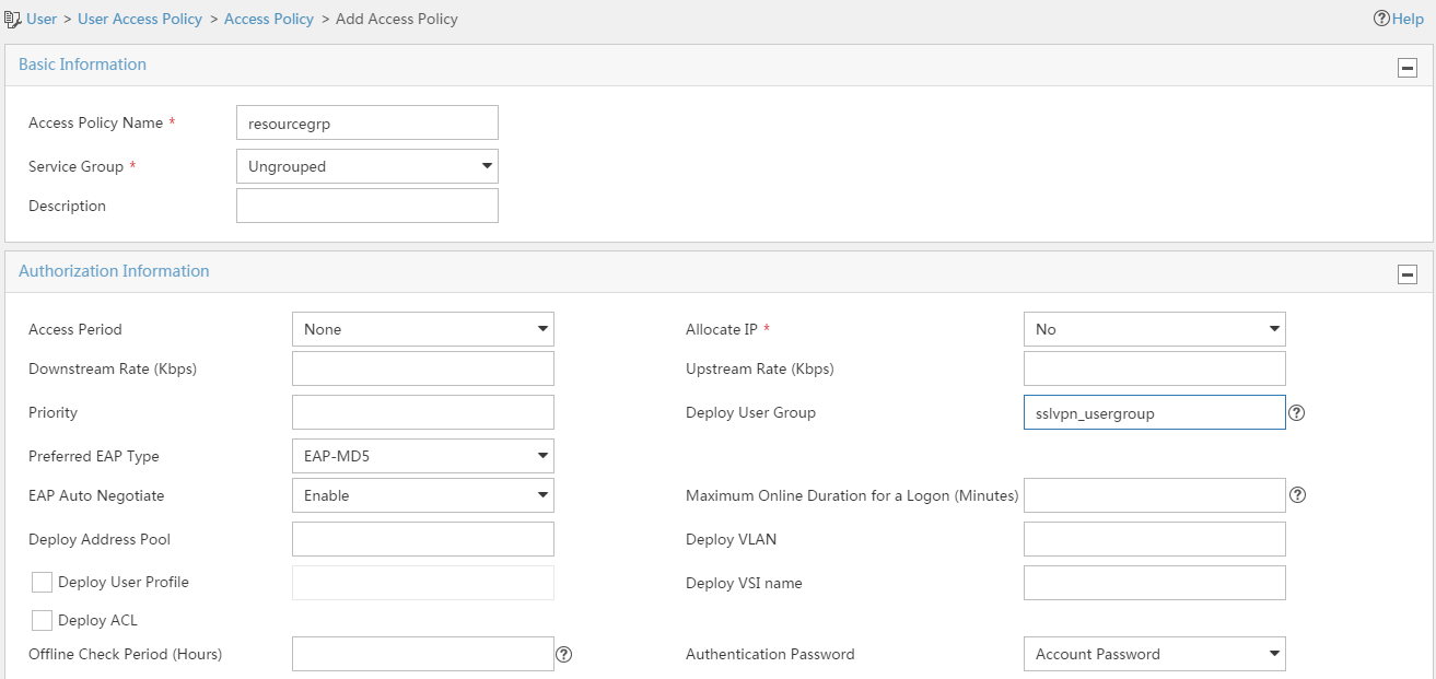
1. Configure an access policy named resourcegrp:
# Log in to IMC.
# On the top navigation bar, click User.
# From the navigation pane, select User Access Policy > Access Policy.
# Click Add.
# Add an access policy as shown in Figure 141.
# Click OK.
Figure 141 Creating an access policy
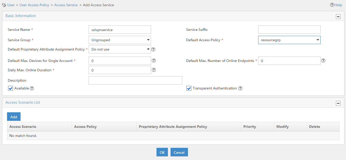
2. Configure an access service named sslvpnservice:
# On the top navigation bar, click User.
# From the navigation pane, select User Access Policy > Access Service.
# Click Add.
# Add an access service as shown in Figure 142. In this example, specify access policy resourcegrp as the default access policy.
# Click OK.
Figure 142 Creating an access service
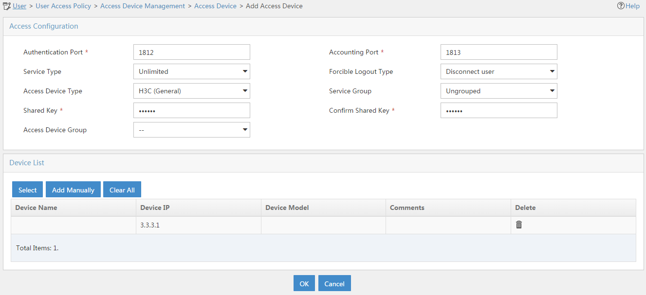
3. Configure an access device:
# On the top navigation bar, click User.
# From the navigation pane, select User Access Policy > Access Device Management > Access Device.
# Click Add.
# Add an access device as shown in Figure 143. In this example, set the shared key to 123456.
# Click OK.
Figure 143 Configuring an access device
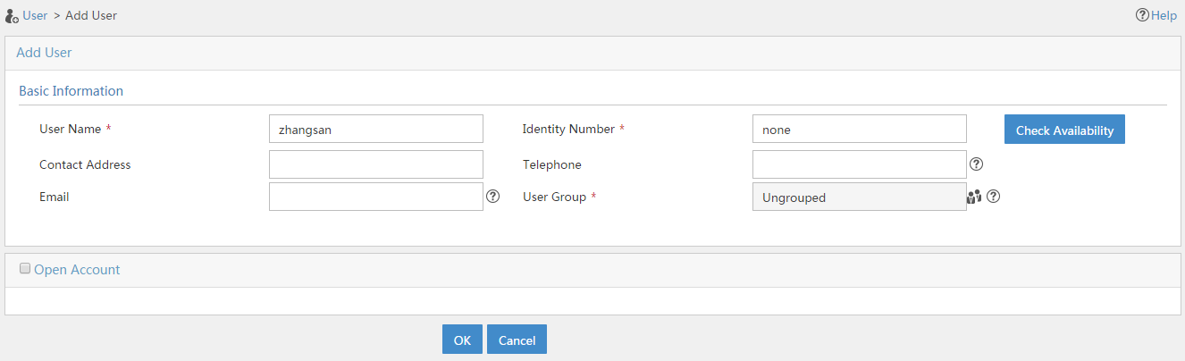
4. Configure an access user:
# Access the User > Add User page.
# Add a platform user as shown in Figure 144.
# Click OK.
Figure 144 Adding a platform user
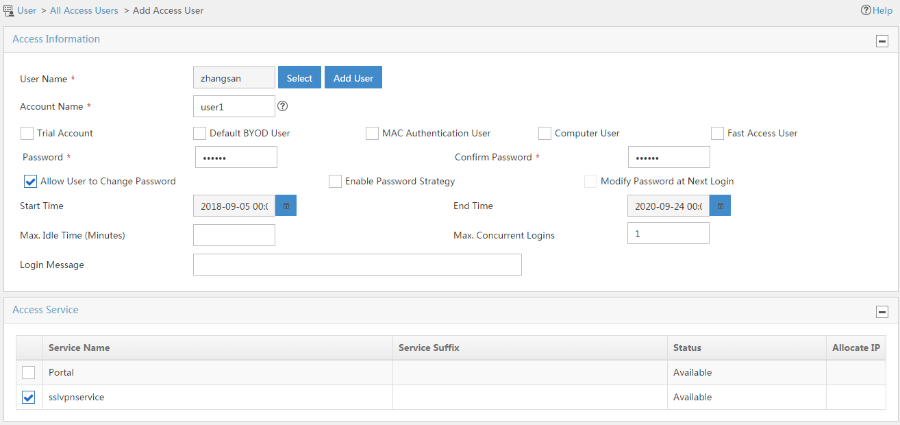
# From the navigation pane, select Access User > All Access Users.
# Click Add.
# Add an access user and assign access service sslvpnservice to the user, as shown in Figure 145.
# Click OK.
Figure 145 Adding an access user
Configuring the host
1. Configure the IP address and gateway address settings for the host and make sure it can reach the SSL VPN gateway and the CA server.
2. Submit a client certificate request to the CA server:
a. Enter http://192.168.100.247/certsrv in the browser address bar.
b. On the certificate service home page shown in Figure 146, click Request a certificate.
Figure 146 Certificate service home page

c. On the Request a Certificate page shown in Figure 147, click advanced certificate request.
Figure 147 Request a Certificate page

d. Create a client certificate request, as shown in Figure 148.
Figure 148 Creating a client certificate request

e. Click Submit.
3. Install the client certificate on the host:
a. After the certificate request is approved by the CA administrator, enter http://192.168.100.247/certsrv in the browser address bar.
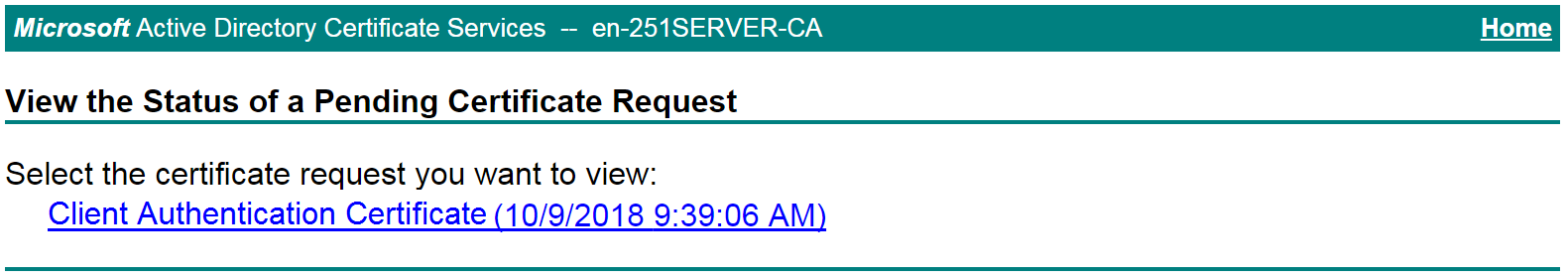
b. On the certificate service home page shown in Figure 149, click View the status of a pending certificate request.
Figure 149 Certificate service home page

The View the Status of a Pending Certificate Request page opens, as shown in Figure 150.
Figure 150 View the Status of a Pending Certificate Request page
c. Click the client certificate whose status you want to view.
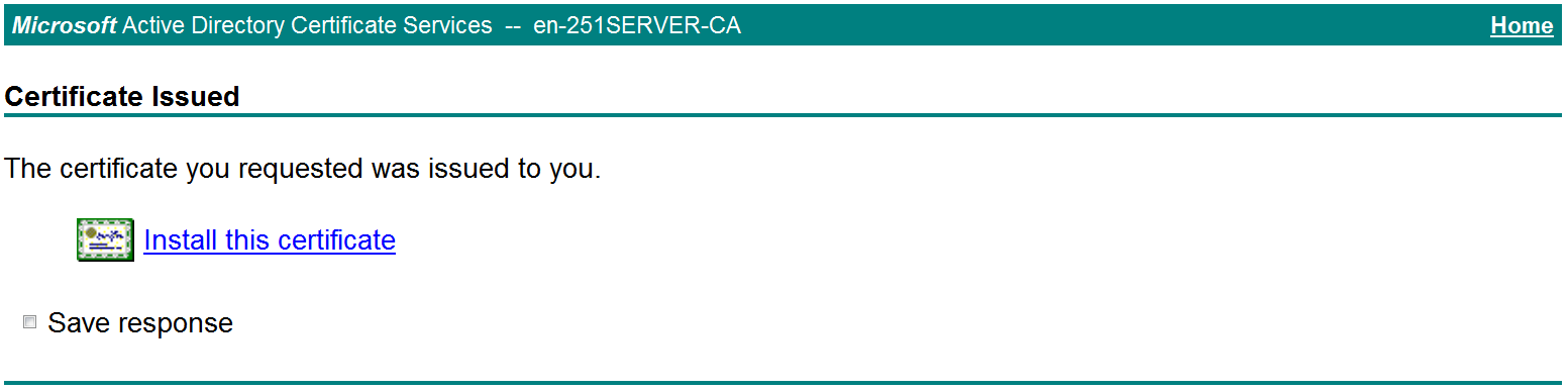
d. On the Certificate Issued page shown in Figure 151, click Install this certificate to install the client certificate.
Figure 151 Installing the client certificate

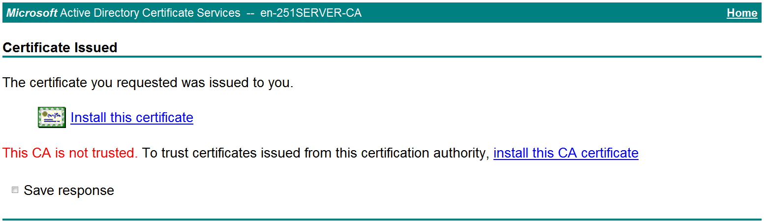
If the host does not have a CA certificate, the page shown in Figure 152 opens. You must install the CA certificate first.
e. Click install this CA certificate to install the CA certificate. Then, click Install this certificate to install the client certificate.
Figure 152 Installing the CA certificate and then the client certificate

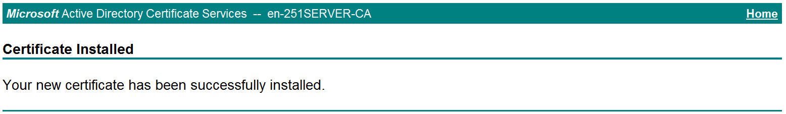
After the client certificate is installed, the Certificate Installed page shown in Figure 153 opens.
Figure 153 Certificate Installed page

Verifying the configuration
1. In the browser address bar of the host, enter https://1.1.1.2 and press Enter.
2. On the Select a certificate page, select the client certificate for authentication, as shown in Figure 154.
Figure 154 Select a certificate page
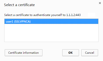
3. Click OK.
4. On the Domain List page shown in Figure 155, select domainip to access the login page.

5. On the login page, enter username user1 and password 123456, and then click Login.
Figure 156 Login page

6. Click START to start the IP client application.
If the host does not have an iNode client installed, the system installs the iNode client, and then starts and connects the iNode client to the SSL VPN gateway.
If the host already has an iNode client installed, the system starts the iNode client and connects it to the SSL VPN gateway directly.
Figure 157 shows that the iNode client is successfully connected to the SSL VPN gateway.
Figure 157 Connecting the iNode client to the SSL VPN gateway

Example: Configure IP access with LDAP authentication
Network configuration
As shown in Figure 158, the device acts as an SSL VPN gateway that connects the public network and the private network. On the private network, a CA server and an LDAP server are deployed and both servers run the Windows Server 2008 R2 operating system. Users need secure access to the internal server (20.2.2.2/24) in IP access mode.
Perform the following tasks:
· Request an SSL server certificate for the device from the CA server.
· Configure the device to require that users pass both password and certificate authentication for IP access.
· Configure the device to use the LDAP server to perform remote authentication and authorization for IP access users.
· Configure the SSL VPN IP access service on the device to allow users to access the internal server in IP access mode.
Software versions used
This configuration example was created and verified on E9345 of the F1060 device.
Restrictions and guidelines
· The IP address pool configured for client address allocation must meet the following requirements:
¡ The address range of the address pool cannot be on the same subnet as the IP address used on the client host.
¡ The IP addresses in the address pool do not conflict with the IP addresses used on the device.
¡ The address range of the address pool cannot be on the same subnet as the IP address of the internal server.
· The SSL VPN AC interface must be added to the correct security zone (Untrust, in this example).
Procedure
Configuring the device
1. Assign IP addresses to interfaces and add the interfaces to security zones.
# On the top navigation bar, click the Network tab.
# From the navigation pane, select Interface Configuration > Interfaces.
# Click the Edit icon for GE 1/0/1.
# In the dialog box that opens, configure the interface:
a. On the Basic Configuration tab, select the Untrust security zone.
b. On the IPv4 Address tab, enter the IP address and mask length of the interface. In this example, enter 1.1.1.2/24.
c. Click OK.
# Add GE 1/0/2 to the Trust security zone and set its IP address to 2.2.2.2/24 in the same way you configure GE 1/0/1.
# Add GE 1/0/3 to the Trust security zone and set its IP address to 3.3.3.1/24 in the same way you configure GE 1/0/1.
2. Configure the security policy between the Trust and Untrust security zones. Make sure the Trust and Untrust security zones can communicate with each other.
3. Request a server certificate for the device:
a. Create a certificate subject:
# On the top navigation bar, click Objects.
# From the navigation pane, select PKI > Certificate Subject.
# Click Create.
# Create a certificate subject as shown in Figure 159, and the click OK.
Figure 159 Creating a certificate subject

b. Create a PKI domain:
# On the Certificate page, click Create PKI domain.
# Create a PKI domain as shown in Figure 160, and then click OK.
Figure 160 Creating a PKI domain

c. Create a certificate request:
# On the Certificate page, click Submit Cert Request.
# Configure the certificate request settings as shown in Figure 161.
Figure 161 Creating a certificate request
# Click OK.
The certificate request content will be displayed, as shown in Figure 162.
Figure 162 Certificate request content

# Copy the certificate request content and click OK.
d. Request a server certificate from the CA:
# Enter http://192.168.100.247/certsrv in the browser address bar.
# On the certificate service home page shown in Figure 163, click Request a certificate.
Figure 163 Certificate service home page

# On the Request a Certificate page shown in Figure 164, click advanced certificate request.
Figure 164 Request a Certificate page

# Paste the previously copied certificate request content in the Base-64-encoded certificate request CMC or PKCS # 10 or PKCS # 7) field, as shown in Figure 165.
Figure 165 Pasting the certificate request content

# Click Submit.
After the certificate request is approved by the CA administrator, enter http://192.168.100.247/certsrv in the browser address bar.
# On the certificate service home page shown in Figure 166, click View the status of a pending certificate request.
Figure 166 Certificate service home page

# Select the certificate request you want to view.
Figure 167 View the Status of a Pending Certificate Request page

The Certificate Issued page opens, indicating that the requested server certificate has been issued, as shown in Figure 168.
Figure 168 Certificate Issued page
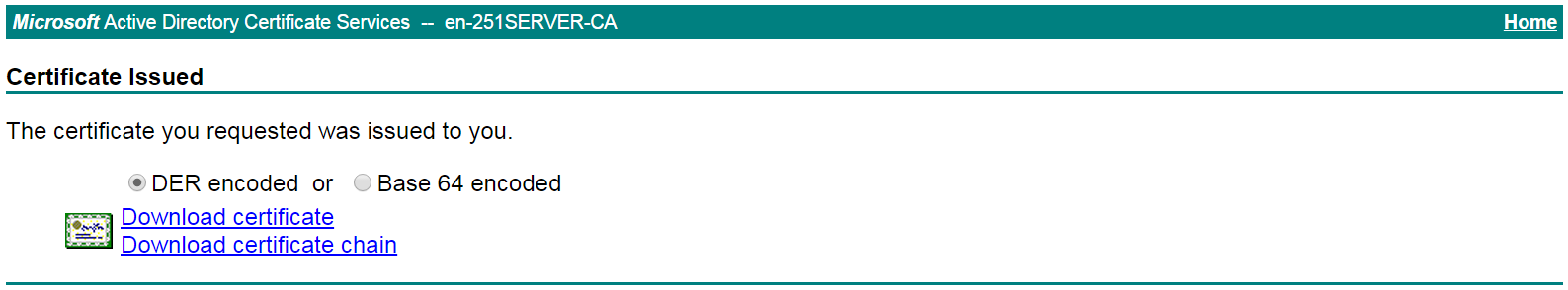
# Click Download certificate to download the server certificate and save it locally.
4. Download the CA certificate:
# Enter http://192.168.100.247/certsrv in the browser address bar.
# On the certificate service home page shown in Figure 169, click Download a CA certificate, certificate chain, or CRL.
Figure 169 Certificate service home page

# On the Download a CA certificate, certificate chain, or CRL page shown in Figure 170, click Download CA certificate.
Figure 170 Download a CA certificate, certificate chain, or CRL page

# Save the downloaded CA certificate locally.
5. Import the CA certificate and server certificate to the PKI domain:
a. Import the CA certificate:
# On the top navigation bar, click Objects.
# From the navigation pane, select PKI > Certificate.
# Click Import certificate.
# Import the locally saved CA certificate, as shown in Figure 171, and then click OK.
Figure 171 Importing the CA certificate

b. Import the server certificate:
# On the Certificate page, click Import certificate.
# Import the locally saved server certificate, as shown in Figure 172, and then click OK.
Figure 172 Importing the server certificate
6. Configure an SSL server policy:
# On the top navigation bar, click Objects.
# From the navigation pane, select SSL > SSL Server Policies.
# Click Create.
# Configure an SSL server policy as shown in Figure 173, and then click OK.
Figure 173 Creating an SSL server policy
7. Configure an SSL client policy:
# On the top navigation bar, click Objects.
# From the navigation pane, select SSL > SSL Client Policies.
# Click Create.
# Configure an SSL client policy as shown in Figure 174, and then click OK.
Figure 174 Creating an SSL client policy

8. Configure LDAP settings at the CLI:
# Configure LDAP server ldap1.
<Device> system-view
[Device] ldap server ldap1
[Device-ldap-server-ldap1] login-dn cn=administrator,cn=users,dc=ldap,dc=com
[Device-ldap-server-ldap1] search-base-dn ou=sslvpn_usergroup,dc=ldap,dc=com
[Device-ldap-server-ldap1] ip 3.3.3.3
[Device-ldap-server-ldap1] login-password simple 123456
[Device-ldap-server-ldap1] quit
# Configure LDAP attribute map test.
[Device] ldap attribute-map test
[Device-ldap-attr-map-test] map ldap-attribute memberof prefix cn= delimiter , aaa-attribute user-group
[Device-ldap-attr-map-test] quit
# Configure LDAP scheme shm1.
[Device] ldap scheme shm1
[Device-ldap-shm1] authentication-server ldap1
[Device-ldap-shm1] authorization-server ldap1
[Device-ldap-shm1] attribute-map test
[Device-ldap-shm1] quit
# Configure ISP domain sslvpn.
[Device] domain sslvpn
[Device-isp-sslvpn] state active
[Device-isp-sslvpn] authentication sslvpn ldap-scheme shm1
[Device-isp-sslvpn] authorization sslvpn ldap-scheme shm1
[Device-isp-sslvpn] accounting sslvpn none
[Device-isp-sslvpn] quit
9. Create a user group:
# On the top navigation bar, click Objects.
# From the navigation pane, select User > User Management > Local Users.
# Click the User Group tab.
# Click Create.
# Create a user group named sslvpn_usergroup and specify SSL VPN resource group resourcegrp for the user group, as shown in Figure 175.
# Click OK.
Figure 175 Creating a user group
10. Configure the SSL VPN gateway:
# On the top navigation bar, click Network.
# From the navigation pane, select SSL VPN > SSL VPN Gateways.
# Click Create.
# Create an SSL VPN gateway as shown in Figure 176, and then click OK.
Figure 176 Creating an SSL VPN gateway

11. Create an SSL VPN AC interface:
# On the top navigation bar, click Network.
# From the navigation pane, select SSL VPN > SSL VPN AC Interfaces.
# Click Create.
# In the Create Interfaces dialog box that opens, enter 1 in the Interface number field and click OK.
# In the Modify Interface Settings dialog box, configure the basic settings for the SSL VPN AC interface as shown in Figure 177.
Figure 177 Configuring basic settings for the SSL VPN AC interface
# Click the IPv4 Address tab and configure the IPv4 address settings for the SSL VPN AC interface as shown in Figure 178.
# Click OK.
Figure 178 Configuring IPv4 address settings for the SSL VPN AC interface

12. Create an address pool for IP access users:
# On the top navigation bar, click Network.
# From the navigation pane, select SSL VPN > IP Access Address Pools.
# Click Create.
# Create an IP access address pool as shown in Figure 179, and then click OK.
Figure 179 Creating an IP access address pool
13. Configure an SSL VPN context:
# On the top navigation bar, click Network.
# From the navigation pane, select SSL VPN > SSL VPN Contexts.
# Click Create.
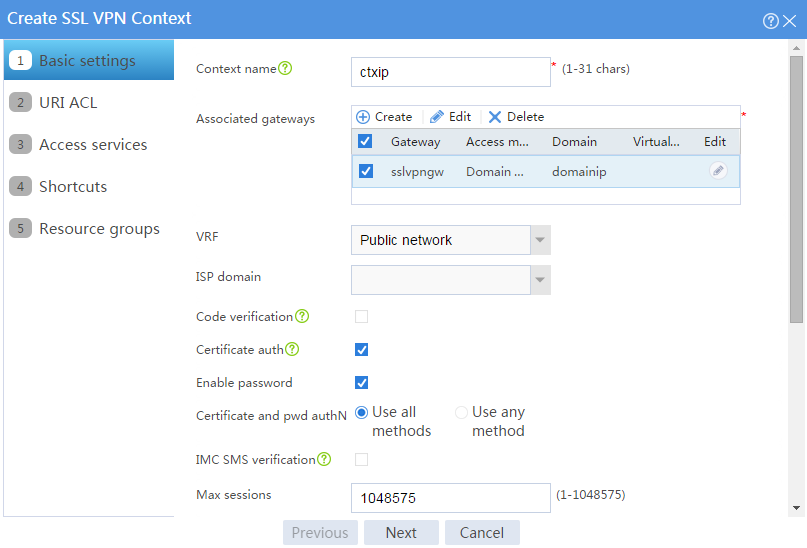
# Configure the basic settings for the SSL VPN context as shown in Figure 180, and then click Next.
Figure 180 Configuring basic settings for an SSL VPN context
# On the URI ACL page, click Next.
# On the Access services page, select IP access and click Next.
# On the IP access page, configure the IP access service as follows:
a. Configure the IP access parameters as shown in Figure 181 and click Next.
Figure 181 Configuring IP access parameters for the IP access service

b. In the IP access resources area, configure route list rtlist with an included route entry for 20.2.2.0/24, as shown in Figure 182.
c. Click Next.
Figure 182 Configuring IP access resources for the IP access service

# Click Next on the Shortcuts page.
# On the Resource groups page, click Create.
# Create a resource group named resourcegrp, as shown in Figure 183. In this example, select route list rtlist as the accessible IP resources and use IPv4 ACL 3999 (which permits all traffic) for IP access request filtering.
Figure 183 Creating an SSL VPN resource group

# Click OK.
The newly created resource group is displayed on the Resource groups page, as shown in Figure 184.
Figure 184 Resource groups configuration page

# Click Finish.
# Select the Enable check box to enable the SSL VPN context, as shown in Figure 185.
Figure 185 Enabling the SSL VPN context

Configure the LDAP server
1. Create user group sslvpn_usergroup:
# On the LDAP server, start the Server Manager by selecting Start > Administrative Tools > Server Manager.
# From the navigation pane, select Roles > Active Directory Domain Services > Active Directory Users and Computers.
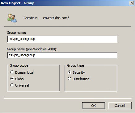
# Right-click Users under the en.cert-dns.com node, and then select New > Group from the shortcut menus.
# Create user group sslvpn_usergroup as shown in Figure 186.
# Click OK.
Figure 186 Creating a user group
2. Create user user1 and add the user to user group sslvpn_usergroup:
# On the LDAP server, start the Server Manager by selecting Start > Administrative Tools > Server Manager.
# From the navigation pane, select Roles > Active Directory Domain Services > Active Directory Users and Computers.
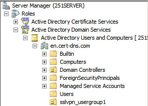
# Right-click the en.cert-dns.com node, and then select New > Organizational Unit from the shortcut menus.
# Create organizational unit sslvpn_usergroup, as shown in Figure 187.
# Click OK.
Figure 187 Creating an organizational unit
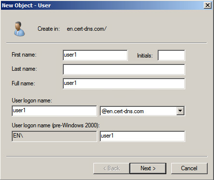
# Right-click sslvpn_usergroup, and then select New > User from the shortcut menus.
# Add user user1 as shown in Figure 188.
# Click Next.
Figure 188 Adding LDAP user user1
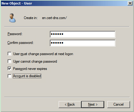
# On the page shown in Figure 189, enter password 123456, select options as needed, and click Next.
Figure 189 Setting the user's password
# Right-click user user1 and select Properties.
# In the dialog box that opens, click the Member Of tab and add user1 to user group sslvpn_usergroup, as show in Figure 190.
Figure 190 Modifying user properties
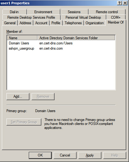
# Click OK.
Configuring the host
1. Configure the IP address and gateway address settings for the host and make sure it can reach the SSL VPN gateway and the CA server.
2. Submit a client certificate request to the CA server:
a. Enter http://192.168.100.247/certsrv in the browser address bar.
b. On the certificate service home page shown in Figure 191, click Request a certificate.
Figure 191 Certificate service home page

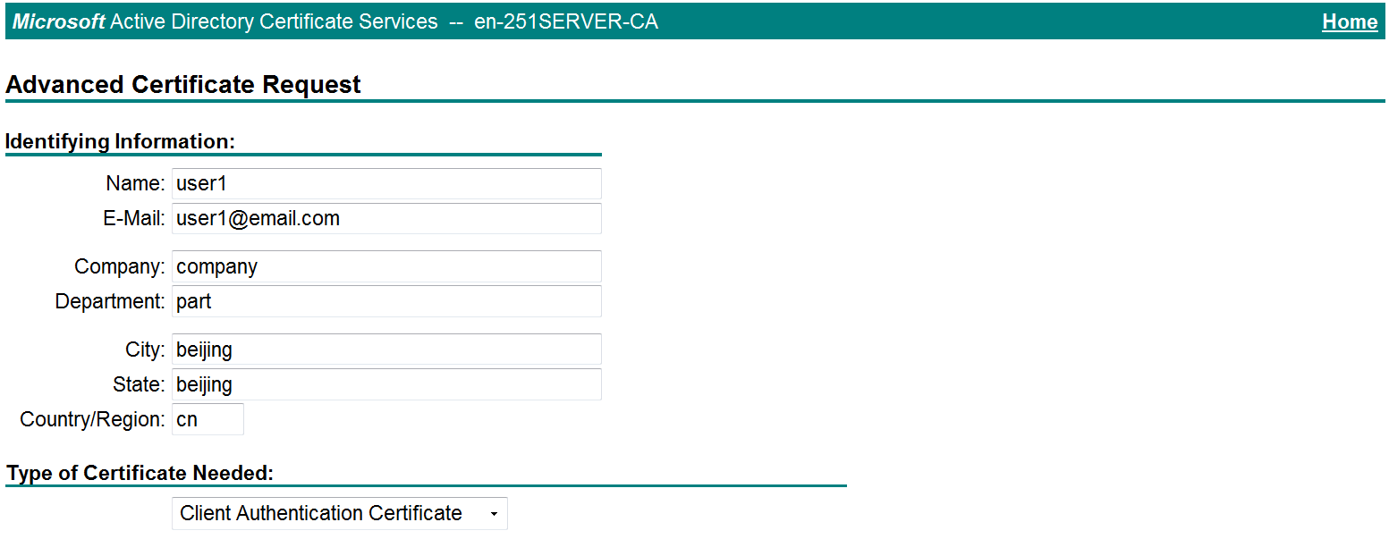
c. On the Request a Certificate page shown in Figure 192, click advanced certificate request.
Figure 192 Request a Certificate page

d. Create a client certificate request, as shown in Figure 193.
Figure 193 Creating a client certificate request
e. Click Submit.
3. Install the client certificate on the host:
a. After the certificate request is approved by the CA administrator, enter http://192.168.100.247/certsrv in the browser address bar.
b. On the certificate service home page shown in Figure 194, click View the status of a pending certificate request.
Figure 194 Certificate service home page

The View the Status of a Pending Certificate Request page opens, as shown in Figure 195.
Figure 195 View the Status of a Pending Certificate Request page

c. Click the client certificate whose status you want to view.
d. On the Certificate Issued page shown in Figure 196, click Install this certificate to install the client certificate.
Figure 196 Installing the client certificate
If the host does not have a CA certificate, the page shown in Figure 197 opens. You must install the CA certificate first.
e. Click install this CA certificate to install the CA certificate. Then, click Install this certificate to install the client certificate.
Figure 197 Installing the CA certificate and then the client certificate
After the client certificate is installed, the Certificate Installed page shown in Figure 198 opens.
Figure 198 Certificate Installed page
Verifying the configuration
1. In the browser address bar of the host, enter https://1.1.1.2 and press Enter.
2. On the Select a certificate page, select the client certificate for authentication, as shown in Figure 199.
Figure 199 Select a certificate page

3. Click OK.
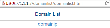
4. On the Domain List page shown in Figure 200, select domainip to access the login page.

5. Select domainip to access the login page.
6. On the login page, enter username user1 and password 123456, and then click Login.
Figure 201 Login page

7. Click START to start the IP client application.
If the host does not have an iNode client installed, the system installs the iNode client, and then starts and connects the iNode client to the SSL VPN gateway.
If the host already has an iNode client installed, the system starts the iNode client and connects it to the SSL VPN gateway directly.
Figure 202 shows that the iNode client is successfully connected to the SSL VPN gateway.
Figure 202 Connecting the iNode client to the SSL VPN gateway