- Table of Contents
-
- 08-Configuration Examples
- 01-Web Login Configuration Examples
- 02-Internet Access Through a Static IP Address Configuration Examples
- 03-Internet access through PPPoE configuration examples
- 04-Signature Library Upgrade Configuration Examples
- 04-Software Upgrade Examples(only for F50X0-D and F5000-AK5X5 firewalls)
- 05-Software Upgrade Examples
- 06-Static routing configuration examples
- 07-OSPF configuration examples
- 08-BGP configuration examples
- 09-RIP configuration examples
- 10-DHCP configuration examples
- 11-DNS configuration examples
- 12-Object Group Configuration Examples
- 13-Public key management configuration examples
- 14-Security Policy Configuration Examples
- 15-Attack defense configuration examples
- 16-Connection Limit Configuration Examples
- 17-IPS Configuration Examples
- 18-URL Filtering Configuration Examples
- 19-Anti-Virus Configuration Examples
- 20-Data Filtering Configuration Examples
- 21-File Filtering Configuration Examples
- 22-APR-Based Security Policy Configuration Examples
- 23-Bandwidth Management Configuration Examples
- 24-NAT configuration examples
- 25-NAT hairpin configuration examples
- 26-IPsec configuration examples
- 27-SSL VPN configuration examples
- 28-Server Load Balancing Configuration Examples
- 29-Outbound Link Load Balancing Configuration Examples
- 30-Inbound Link Load Balancing Configuration Examples
- 31-Transparent DNS Proxy Configuration Examples
- 32-Context Configuration Examples
- 32-Context Configuration Examples(only for F50X0-D and F5000-AK5X5 firewalls)
- 33-IRF configuration examples
- 34-High Availability Group Configuration Examples
- 35-NAT Flow Logging Configuration Examples
- 36-User identification configuration examples
- 37-Server Connection Detection Configuration Examples
- 38-IP Reputation Configuration Examples
- 39-NPTv6 Configuration Examples
- 40-SSL Decryption Configuration Examples
- 41-MAC Address Learning Through a Layer 3 Device Configuration Examples
- 42-WAF Configuration Examples
- 43-NetShare Control Configuration Examples
- 44-4G Configuration Examples
- 45-WLAN Configuration Examples
- Related Documents
-
| Title | Size | Download |
|---|---|---|
| 39-NPTv6 Configuration Examples | 117.07 KB |
Introduction
The following information provides NPTv6 configuration examples.
IPv6-to-IPv6 Network Prefix Translation (NPTv6), also known as NAT66, translates the internal IPv6 prefix in the IPv6 packet header to an external IPv6 prefix and vice versa.
NPTv6 supports the following address translation methods:
· Source address translation—Translates source IPv6 addresses in packets when internal users access an external network.
· Destination address translation—Translates destination IPv6 addresses in packets when external hosts access servers in the internal network.
This document is not restricted to specific software or hardware versions. Procedures and information in the examples might be slightly different depending on the software or hardware version of the device.
The configuration examples were created and verified in a lab environment, and all the devices were started with the factory default configuration. When you are working on a live network, make sure you understand the potential impact of every command on your network.
The following information is provided based on the assumption that you have basic knowledge of the NPTv6 feature.
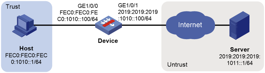
Network configuration
As shown in Figure 1, configure source address translation on the device to allow internal users to access the server in the external network.
Software versions used
This configuration example was created and verified on F9345 of the F1060 device.
Procedure
1. Assign IP addresses to interfaces and add the interfaces to security zones.
# On the top navigation bar, click Network.
# From the navigation pane, select Interface Configuration > Interfaces.
# Click the Edit icon for GE 1/0/1.
# In the dialog box that opens, configure the interface:
a. Select the Untrust security zone.
b. On the IPv6 Address tab, enter the IPv6 global unicast address and prefix of the interface. In this example, enter 2019:2019:2019:1010::100/64.
c. Retain the default configuration for the rest of parameters.
d. Click OK.
# Add GE 1/0/0 to the Trust security zone and set its IPv6 global unicast address to FEC0:FEC0:FEC0:1010::100/64 in the same way you configure GE 1/0/1.
2. Create a route.
The following configuration example involves only static route for illustration. To apply a dynamic route, you can configure a dynamic routing protocol as needed.
# On the top navigation bar, click Network.
# From the navigation pane, select Routing > Static Routing > IPv6 Static Routing.
# Click Create.
# In the dialog box that opens, create an IPv6 static route.
¡ Enter 2019:2019:2019:1011::1 as the destination address.
¡ Set the prefix length to 64.
¡ Enter 2019:2019:2019:1010::101 as the next hop.
¡ Retain the default configuration for the rest of parameters.
# Click OK.
3. Create a security policy.
# On the top navigation bar, click Policies.
# From the navigation pane, select Security Policies > Security Policies.
# Click Create.
# In the dialog box that appears, configure a security policy to allow packets from the internal network to pass through.
¡ Enter policy name Secpolicy.
¡ Select source zone Trust.
¡ Select destination zone Untrust.
¡ Select type IPv6.
¡ Select action Permit.
¡ Enter FEC0:FEC0:FEC0:1010::1 as the source address.
¡ Enter 2019:2019:2019:1011::1 as the destination address.
¡ Retain the default configuration for the rest of parameters.
# Click OK.
4. Configure NPTv6.
# On the top navigation bar, click Policies.
# From the navigation pane, select NAT66 > NAT66 Prefix Translation.
# Click Create.
# Create a prefix translation mapping, as shown in Figure 2.
Figure 2 Creating a NAT66 prefix translation mapping
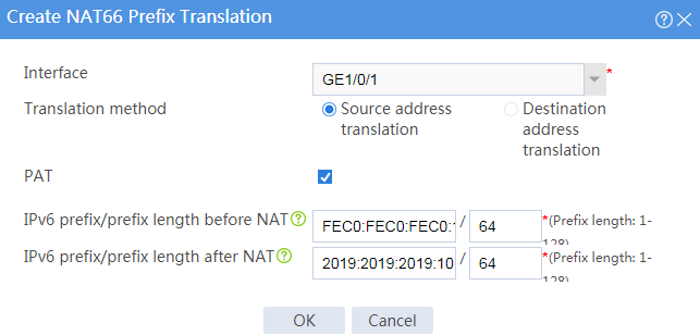
# Click OK.
Verifying the configuration
1. Verify that the host can successfully ping the server in the external network.
C:\Users\abc>ping 2019:2019:2019:1011::1
Pinging 2019:2019:2019:1011::1 with 32 bytes of data:
Reply from 2019:2019:2019:1011::1: bytes=32 time<1ms TTL=253
Reply from 2019:2019:2019:1011::1: bytes=32 time<1ms TTL=253
Reply from 2019:2019:2019:1011::1: bytes=32 time<1ms TTL=253
Reply from 2019:2019:2019:1011::1: bytes=32 time<1ms TTL=253
Ping statistics for 2019:2019:2019:1011::1:
Packets: Sent = 4, Received = 4, Lost = 0 (0% loss),
Approximate round trip times in milli-seconds:
Minimum = 0ms, Maximum = 0ms, Average = 0ms
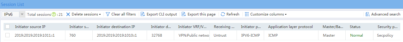
2. Verify that a session is generated when the host accesses the server.
# On the top navigation bar, click Monitor.
# From the navigation pane, select Sessions.
Figure 3 Session list
Example: Configuring destination address translation
Network configuration
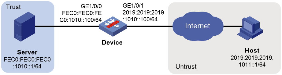
As shown in Figure 4, configure destination address translation on the device to allow the external host to access the internal Web server.
Software versions used
This configuration example was created and verified on F9345 of the F1060 device.
Procedure
1. Assign IP addresses to interfaces and add the interfaces to security zones.
# On the top navigation bar, click Network.
# From the navigation pane, select Interface Configuration > Interfaces.
# Click the Edit icon for GE 1/0/1.
# In the dialog box that opens, configure the interface:
a. Select the Untrust security zone.
b. On the IPv6 Address tab, enter the IPv6 global unicast address and prefix of the interface. In this example, enter 2019:2019:2019:1010::100/64.
c. Retain the default configuration for the rest of parameters.
d. Click OK.
# Add GE 1/0/0 to the Trust security zone and set its IPv6 address to FEC0:FEC0:FEC0:1010::100/64 in the same way you configure GE 1/0/1.
2. Create a route.
The following configuration example involves only static route for illustration. To apply a dynamic route, you can configure a dynamic routing protocol as needed.
# On the top navigation bar, click Network.
# From the navigation pane, select Routing > Static Routing > IPv6 Static Routing.
# Click Create.
# In the dialog box that opens, create an IPv6 static route.
¡ Enter :: as the destination address.
¡ Set the prefix length to 0.
¡ Enter 2019:2019:2019:1010::101 as the next hop.
¡ Retain the default configuration for the rest of parameters.
# Click OK.
3. Create a security policy.
# On the top navigation bar, click Policies.
# From the navigation pane, select Security Policies > Security Policies.
# Click Create.
# In the dialog box that appears, configure a security policy to allow packets from the external host to pass through.
¡ Enter policy name Secpolicy.
¡ Select source zone Untrust.
¡ Select destination zone Trust.
¡ Select type IPv6.
¡ Select action Permit.
¡ Enter 2019:2019:2019:1011::1 as the source address.
¡ Enter FEC0:FEC0:FEC0:1010::1 as the destination address.
¡ Retain the default configuration for the rest of parameters.
# Click OK.
4. Configure NPTv6.
# On the top navigation bar, click Policies.
# From the navigation pane, select NAT66 > NAT66 Prefix Translation.
# Click Create.
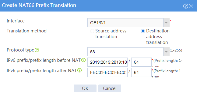
# Create a prefix translation mapping, as shown in Figure 5.
Figure 5 Creating a NAT66 prefix translation mapping
# Click OK.
Verifying the configuration
1. Verify that the host can successfully ping the internal Web server.
C:\Users\abc>ping 2019:2019:2019:1011::1
Pinging 2019:2019:2019:1011::1 with 32 bytes of data:
Reply from 2019:2019:2019:1011::1: bytes=32 time<1ms TTL=253
Reply from 2019:2019:2019:1011::1: bytes=32 time<1ms TTL=253
Reply from 2019:2019:2019:1011::1: bytes=32 time<1ms TTL=253
Reply from 2019:2019:2019:1011::1: bytes=32 time<1ms TTL=253
Ping statistics for 2019:2019:2019:1011::1:
Packets: Sent = 4, Received = 4, Lost = 0 (0% loss),
Approximate round trip times in milli-seconds:
Minimum = 0ms, Maximum = 0ms, Average = 0ms
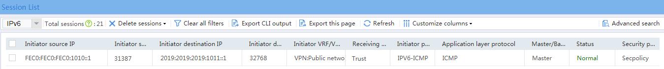
2. Verify that a session is generated when the host accesses the internal Web server.
# On the top navigation bar, click Monitor.
# From the navigation pane, select Sessions.
Figure 6 Session list