- Table of Contents
-
- 08-Configuration Examples
- 01-Web Login Configuration Examples
- 02-Internet Access Through a Static IP Address Configuration Examples
- 03-Internet access through PPPoE configuration examples
- 04-Signature Library Upgrade Configuration Examples
- 04-Software Upgrade Examples(only for F50X0-D and F5000-AK5X5 firewalls)
- 05-Software Upgrade Examples
- 06-Static routing configuration examples
- 07-OSPF configuration examples
- 08-BGP configuration examples
- 09-RIP configuration examples
- 10-DHCP configuration examples
- 11-DNS configuration examples
- 12-Object Group Configuration Examples
- 13-Public key management configuration examples
- 14-Security Policy Configuration Examples
- 15-Attack defense configuration examples
- 16-Connection Limit Configuration Examples
- 17-IPS Configuration Examples
- 18-URL Filtering Configuration Examples
- 19-Anti-Virus Configuration Examples
- 20-Data Filtering Configuration Examples
- 21-File Filtering Configuration Examples
- 22-APR-Based Security Policy Configuration Examples
- 23-Bandwidth Management Configuration Examples
- 24-NAT configuration examples
- 25-NAT hairpin configuration examples
- 26-IPsec configuration examples
- 27-SSL VPN configuration examples
- 28-Server Load Balancing Configuration Examples
- 29-Outbound Link Load Balancing Configuration Examples
- 30-Inbound Link Load Balancing Configuration Examples
- 31-Transparent DNS Proxy Configuration Examples
- 32-Context Configuration Examples
- 32-Context Configuration Examples(only for F50X0-D and F5000-AK5X5 firewalls)
- 33-IRF configuration examples
- 34-High Availability Group Configuration Examples
- 35-NAT Flow Logging Configuration Examples
- 36-User identification configuration examples
- 37-Server Connection Detection Configuration Examples
- 38-IP Reputation Configuration Examples
- 39-NPTv6 Configuration Examples
- 40-SSL Decryption Configuration Examples
- 41-MAC Address Learning Through a Layer 3 Device Configuration Examples
- 42-WAF Configuration Examples
- 43-NetShare Control Configuration Examples
- 44-4G Configuration Examples
- 45-WLAN Configuration Examples
- Related Documents
-
| Title | Size | Download |
|---|---|---|
| 10-DHCP configuration examples | 192.68 KB |
Introduction
The following information describes DHCP configuration examples.
The Dynamic Host Configuration Protocol (DHCP) provides a framework to assign configuration information to network devices.
DHCP uses the client-server model for network configuration parameter assignment. DHCP clients request network configuration parameters from a DHCP server and the DHCP server assigns network configuration parameters to DHCP clients. This document provides configuration of the DHCP server.
This document is not restricted to specific software or hardware versions. Procedures and information in the examples might be slightly different depending on the software or hardware version of the device.
The configuration examples were created and verified in a lab environment, and all the devices were started with the factory default configuration. When you are working on a live network, make sure you understand the potential impact of every command on your network.
The following information is provided based on the assumption that you have basic knowledge of DHCP.
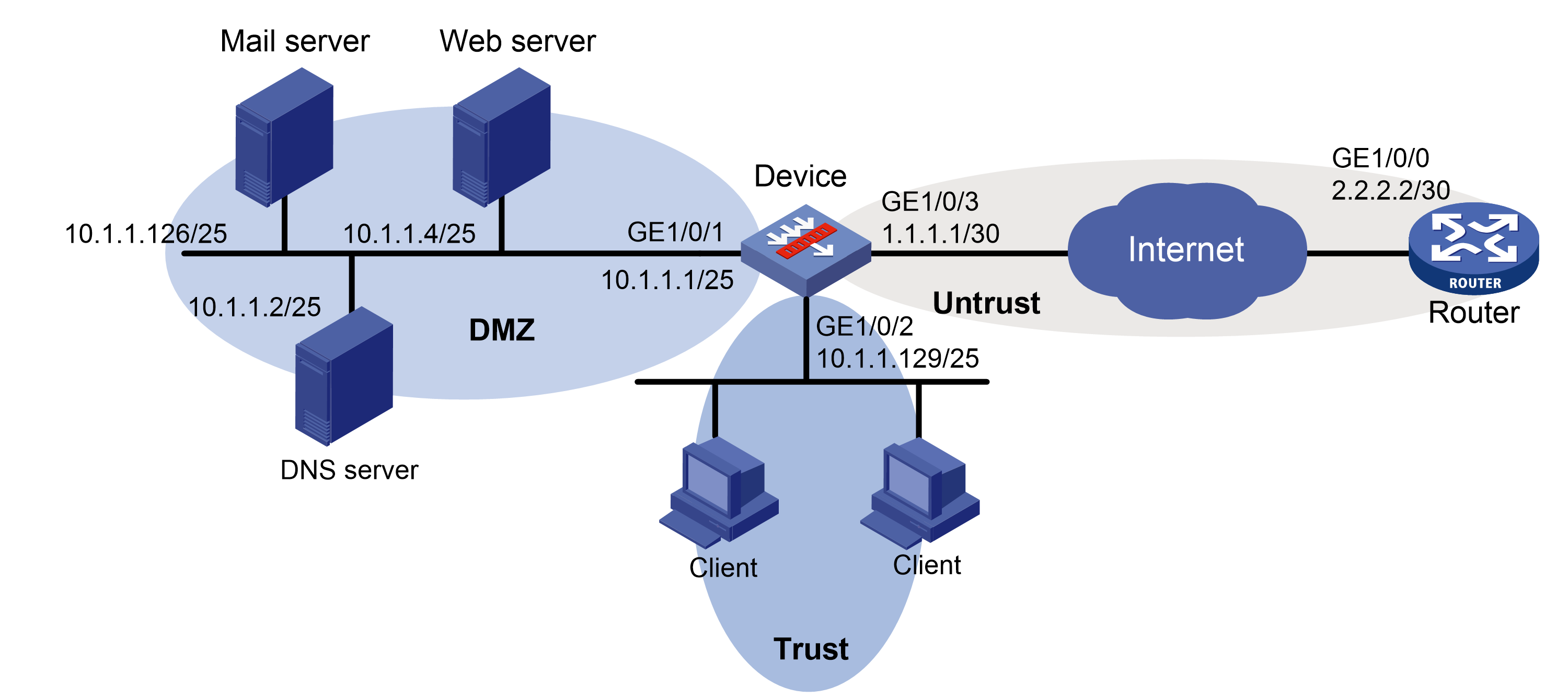
Network configuration
As shown in Figure 1, clients and internal servers are on different subnets. Create DHCP address pools on the device to meet the following requirements:
· The internal servers obtain static IP addresses, the DNS server address, and the gateway from the device.
· Clients dynamically obtain IP addresses from the device.
Software versions used
This configuration example was created and verified on F9345 of the F1060 device.
Restrictions and guidelines
· Make sure the network segment for dynamic allocation is on the same subnet as the DHCP server-enabled interface. Otherwise, clients cannot obtain IP addresses from the DHCP server.
· To ensure the communication between the local security zone and the security zone of the DHCP server-enabled interface, configure a security policy between the local security zone and the DHCP server-enabled interface.
Procedure
1. Assign IP addresses to interfaces.
# On the top navigation bar, click Network.
# From the navigation pane, select Interface Configuration > Interfaces.
# Click the Edit icon for GE 1/0/1.
# In the dialog box that opens, configure the interface:
a. Select the DMZ security zone.
b. On the IPv4 Address tab, enter the IP address and mask of the interface. In this example, enter 10.1.1.1/25.
Retain the default configuration for the remaining parameters.
c. Click OK.
# Add GE 1/0/2 to the Trust security zone and set its IP address to 10.1.1.129/25 in the same way you configure GE 1/0/1.
# Add GE 1/0/3 to the Untrust security zone and set its IP address to 1.1.1.1/30 in the same way you configure GE 1/0/1.
2. Create security policies.
# On the top navigation bar, click Policies.
# From the navigation pane, select Security Policies > Security Policies.
# Select Create > Create a policy.
# Create security policy dhcp-a:
¡ Enter policy name dhcp-a.
¡ Select source zone Trust.
¡ Select destination zone Local.
¡ Select type IPv4.
¡ Select action Permit.
# Click OK.
# Create security policy dhcp-b:
¡ Enter policy name dhcp-b.
¡ Select source zone Local.
¡ Select destination zone Trust.
¡ Select type IPv4.
¡ Select action Permit.
# Click OK.
# Create security policy dhcp-c:
¡ Enter policy name dhcp-c.
¡ Select source zone DMZ.
¡ Select destination zone Local.
¡ Select type IPv4.
¡ Select action Permit.
# Click OK.
# Create security policy dhcp-d:
¡ Enter policy name dhcp-d.
¡ Select source zone Local.
¡ Select destination zone DMZ.
¡ Select type IPv4.
¡ Select action Permit.
# Click OK.
3. Configure statically assigned IP addresses.
# On the top navigation bar, click Network.
# From the navigation pane, select DHCP > DHCP service.
# Select Enable for DHCP service.
# From the navigation pane, select DHCP > DHCP Address Pools.
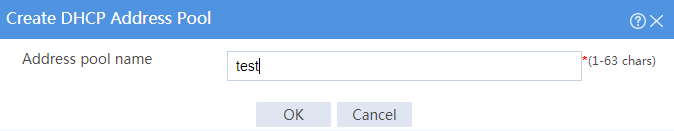
# Click Create address pool.
# Enter the address pool name, and click OK, as shown in Figure 2.
Figure 2 Creating a DHCP address pool
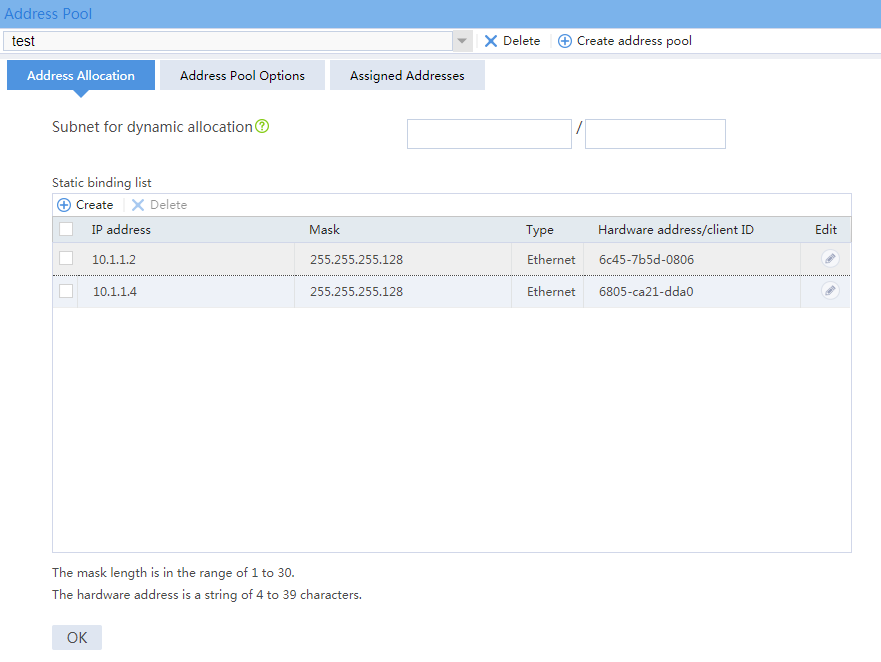
# Click the Address Allocation tab.
# Add statically assigned IP addresses, as shown in Figure 3.
Figure 3 Configuring address allocation
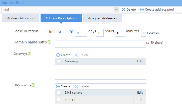
# Click the Address Pool Options tab, and configure address pool options as shown in Figure 4.
Figure 4 Configuring address pool options
# Click OK.
4. Configure dynamic address allocation.
# On the top navigation bar, click Network.
# From the navigation pane, select DHCP > DHCP service.
# Select Enable for DHCP service.
# From the navigation pane, select DHCP > DHCP Address Pools.
# Click Create address pool.
# Enter the address pool name, and click OK, as shown in Figure 5.
Figure 5 Creating a DHCP address pool

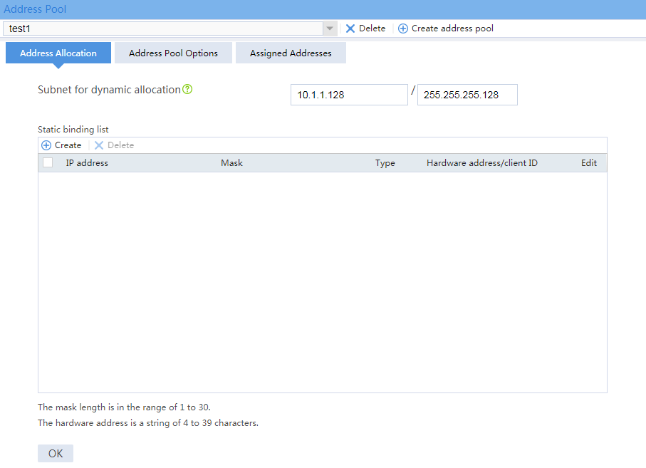
# Click the Address Allocation tab.
# Enter a subnet address for dynamic allocation. The configuration is shown in Figure 6.
Figure 6 Configuring address allocation
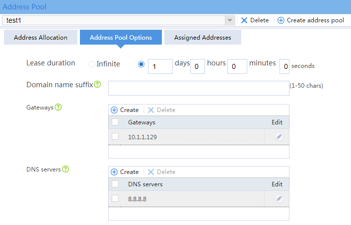
# Click the Address Pool Options tab, add the gateway address and the DNS server address as shown in Figure 7.
Figure 7 Configuring address pool options
# Click OK.
Verifying the configuration
Verifying statically-bound IP address allocation
# On the top navigation bar, click Network.
# From the navigation pane, select DHCP > DHCP Address Pools.
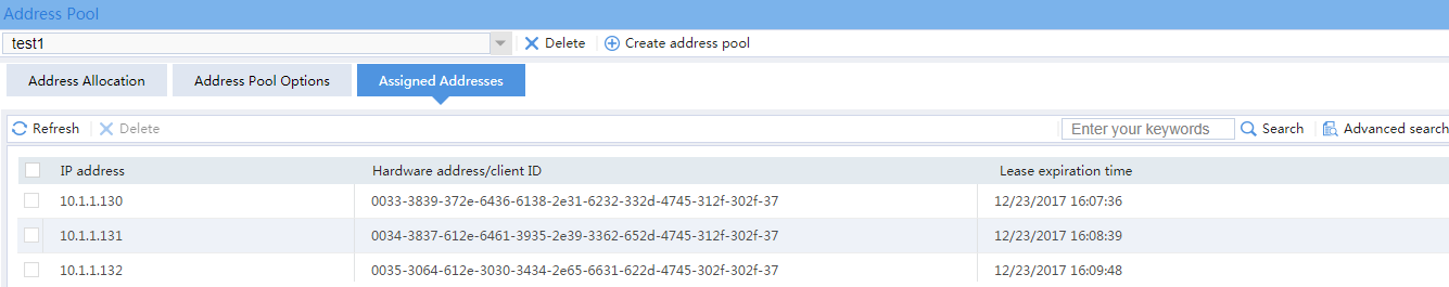
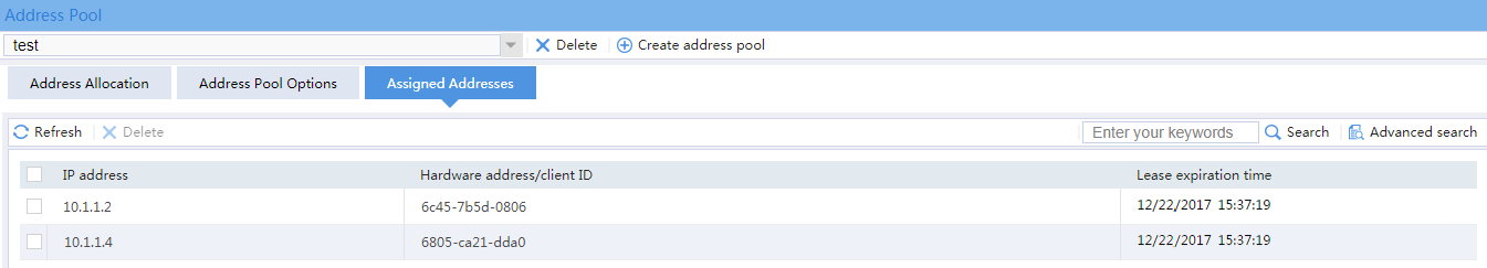
# Select the DHCP address pool for the static allocation, and click the Assigned Addresses tab.
# Verify that the device has assigned static addresses to internal servers.
Figure 8 Verifying statically assigned IP addresses
Verifying dynamic IP address allocation
# On the top navigation bar, click Network.
# From the navigation pane, select DHCP > DHCP Address Pools.
# Select the DHCP address pool for dynamic allocation, and click the Assigned Addresses tab.
# Verify that the device has dynamically assigned addresses to clients.
Figure 9 Verifying dynamically assigned IP addresses