- Table of Contents
-
- 08-Configuration Examples
- 01-Web Login Configuration Examples
- 02-Internet Access Through a Static IP Address Configuration Examples
- 03-Internet access through PPPoE configuration examples
- 04-Signature Library Upgrade Configuration Examples
- 04-Software Upgrade Examples(only for F50X0-D and F5000-AK5X5 firewalls)
- 05-Software Upgrade Examples
- 06-Static routing configuration examples
- 07-OSPF configuration examples
- 08-BGP configuration examples
- 09-RIP configuration examples
- 10-DHCP configuration examples
- 11-DNS configuration examples
- 12-Object Group Configuration Examples
- 13-Public key management configuration examples
- 14-Security Policy Configuration Examples
- 15-Attack defense configuration examples
- 16-Connection Limit Configuration Examples
- 17-IPS Configuration Examples
- 18-URL Filtering Configuration Examples
- 19-Anti-Virus Configuration Examples
- 20-Data Filtering Configuration Examples
- 21-File Filtering Configuration Examples
- 22-APR-Based Security Policy Configuration Examples
- 23-Bandwidth Management Configuration Examples
- 24-NAT configuration examples
- 25-NAT hairpin configuration examples
- 26-IPsec configuration examples
- 27-SSL VPN configuration examples
- 28-Server Load Balancing Configuration Examples
- 29-Outbound Link Load Balancing Configuration Examples
- 30-Inbound Link Load Balancing Configuration Examples
- 31-Transparent DNS Proxy Configuration Examples
- 32-Context Configuration Examples
- 32-Context Configuration Examples(only for F50X0-D and F5000-AK5X5 firewalls)
- 33-IRF configuration examples
- 34-High Availability Group Configuration Examples
- 35-NAT Flow Logging Configuration Examples
- 36-User identification configuration examples
- 37-Server Connection Detection Configuration Examples
- 38-IP Reputation Configuration Examples
- 39-NPTv6 Configuration Examples
- 40-SSL Decryption Configuration Examples
- 41-MAC Address Learning Through a Layer 3 Device Configuration Examples
- 42-WAF Configuration Examples
- 43-NetShare Control Configuration Examples
- 44-4G Configuration Examples
- 45-WLAN Configuration Examples
- Related Documents
-
| Title | Size | Download |
|---|---|---|
| 36-User identification configuration examples | 1.91 MB |
User identification configuration examples
Introduction
The following information provides user identification configuration examples.
The user identification feature identifies users by IP addresses. This feature works with other security features to control network access on a per-user basis.
The feature enables the device to perform the following tasks:
· Implements security policies on a per-user basis to improve the policy usability.
· Collects statistics and analysis for network attack behaviors and traffic flow on a per-user basis to track the user network access behaviors in real time.
· Implements policy control regardless of changes to the user IP addresses.
The RADIUS single sign-on service enables a RADIUS server to synchronize user identity information (for example, the username and IP address) to a security device (for example, a firewall) so the users can access the network without having to authenticate with the device after they pass authentication with the RADIUS server.
This document is not restricted to specific software or hardware versions. Procedures and information in the examples might be slightly different depending on the software or hardware version of the device.
The configuration examples were created and verified in a lab environment, and all the devices were started with the factory default configuration. When you are working on a live network, make sure you understand the potential impact of every command on your network.
The following information is provided based on the assumption that you have basic knowledge of the portal, AAA, user identification, and security policy features.
General restrictions and guidelines
When you configure security policies and packet filtering policies, make sure they can take effect as you expected. Security policies process packets prior to packet filtering policies. Packet filtering policies will not process the packets that have matched security policies.
Example: Configuring user identification for portal users that pass RADIUS authentication (RADIUS single sign-on)
Network configuration
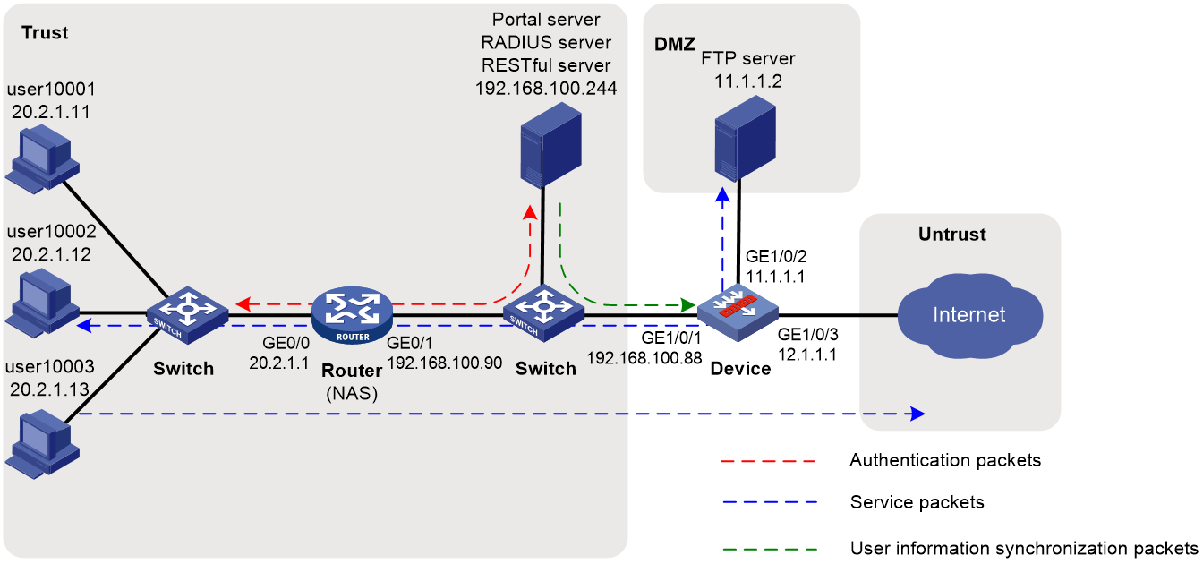
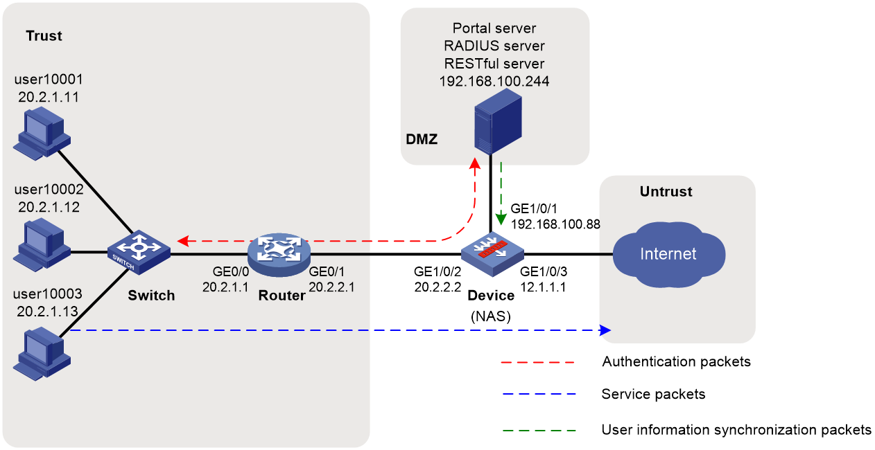
As shown in Figure 1:
· Users user10001, user10002, and user10003 use static IP addresses, and they must pass portal authentication to access the network.
· The router acts as a NAS for the users to access the network. The NAS uses the RADIUS server to authenticate the users.
· The RADIUS server is installed with IMC components. For portal authentication, the server acts as both the portal authentication server and portal Web server.
· The RESTful server stores user account information. The server can synchronize user identity information to Device.
· Device is a firewall. The users can access the network without having to authenticate with the firewall after they pass authentication with the RADIUS server.
· The firewall performs the following identity-based access control on the users that have passed portal authentication:
¡ User user10001 cannot access the FTP server or Internet.
¡ User user10002 can access the FTP server but cannot access the Internet.
¡ User user10003 can access the Internet but cannot access the FTP server.
¡ Users from the Internet cannot access the hosts in the Trust and DMZ security zones.
Analysis
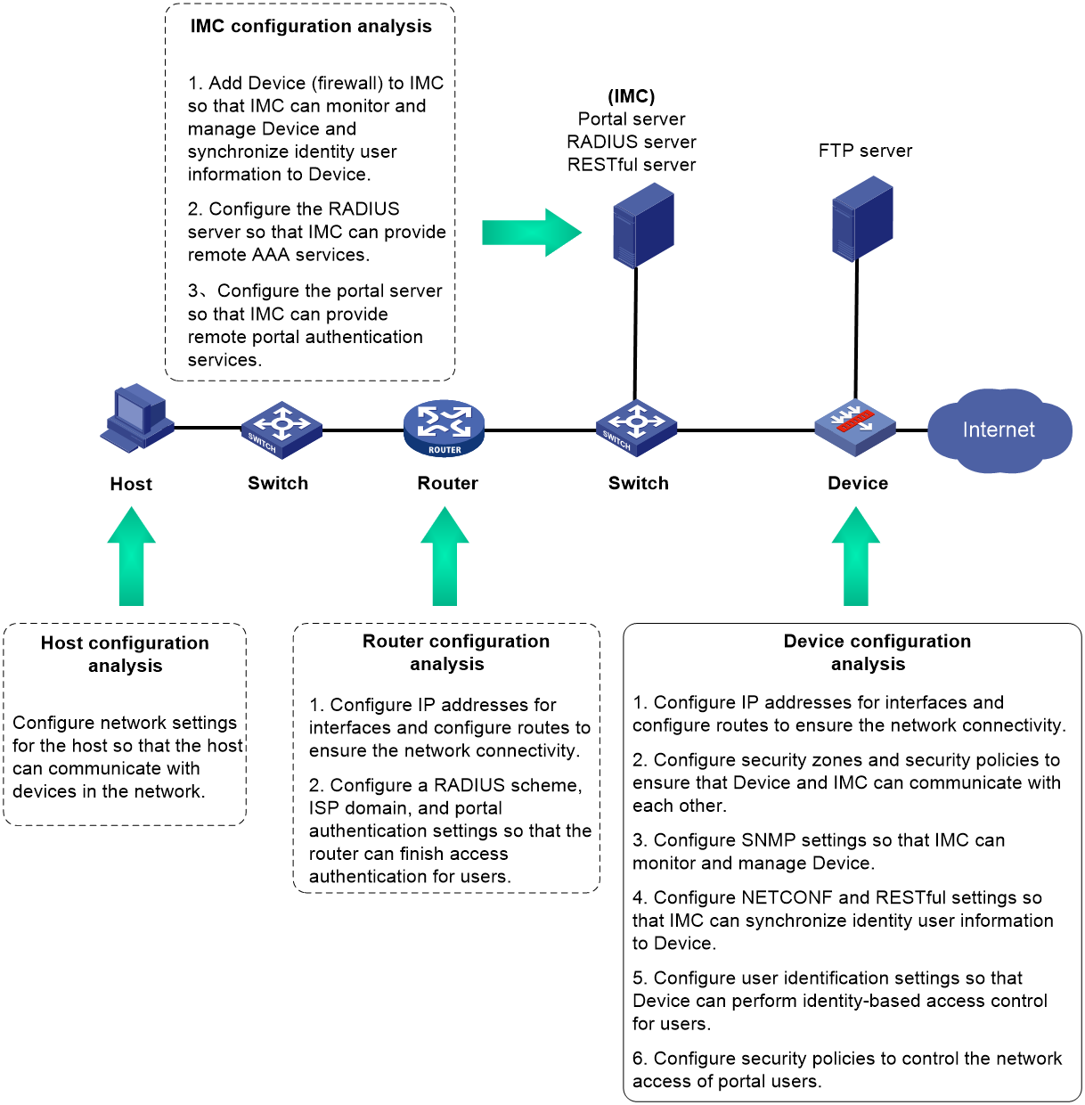
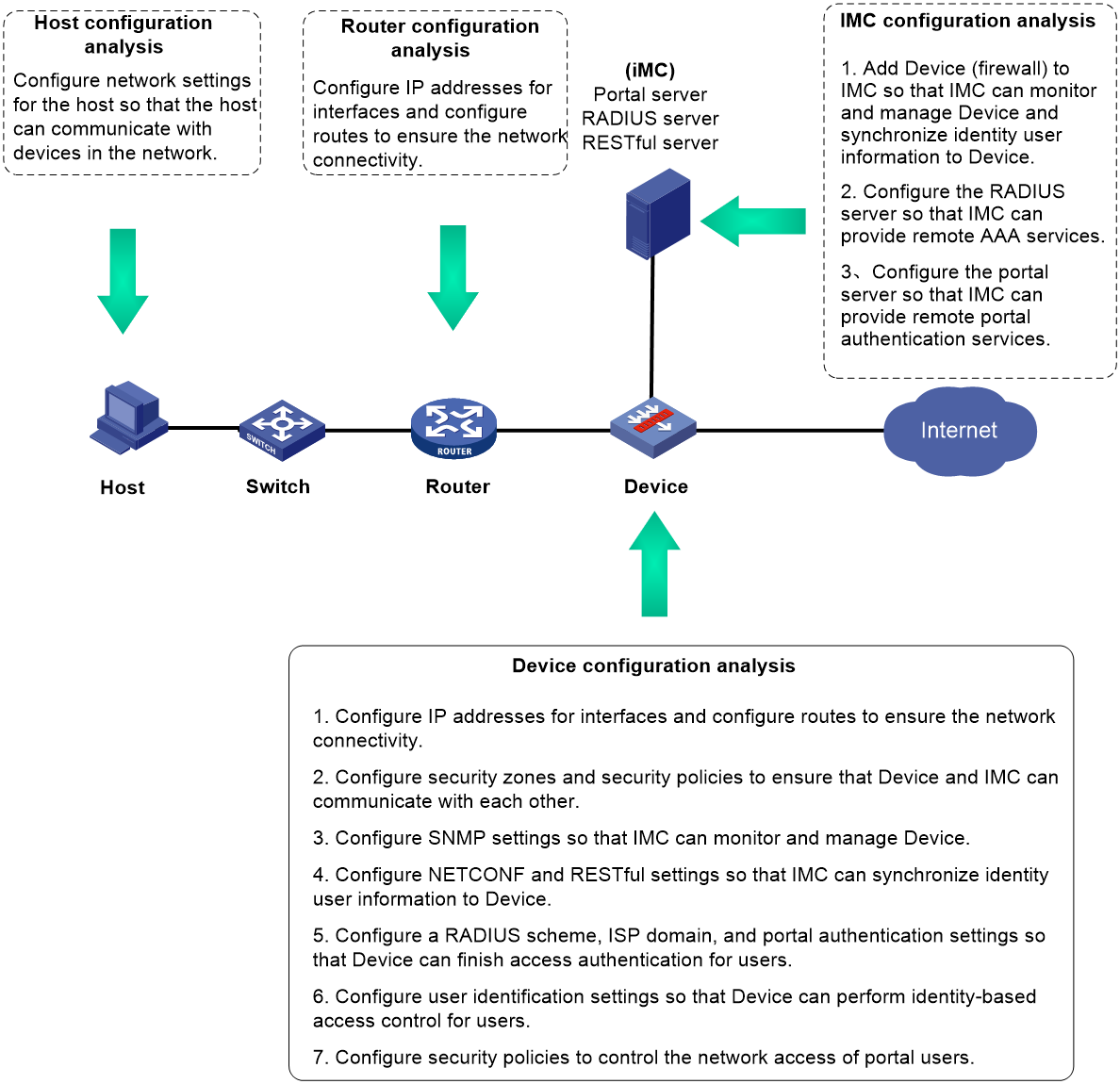
Figure 2 Analysis diagram
Software versions used
This configuration example was created and verified on the following software versions:
· F9345 of the F1060 device.
· Version 7.1.064, ESS 0701 of the MSR26-30 router.
The RADIUS and portal server is installed with IMC PLAT 7.3 (E0506), IMC UAM 7.3 (E0503), IMC CAMS 7.3 (E0501), and IMC SSM 7.3 (E0501).
Restrictions and guidelines
An IMC server logs off an online user only after it receives an accounting-stop request for that user. For the NAS to send accounting-stop requests to the server, you need to configure accounting settings in the authentication domain of the user on the NAS. However, you do not need to configure accounting parameters on the IMC server since accounting is not required.
Procedure
Configuring the router
Configuring IP addresses for interfaces and a default route to ensure the network connectivity of the router
# Assign IP address 20.2.1.1 to GigabitEthernet 0/0.
<Router> system-view
[Router] interface gigabitethernet 0/0
[Router-GigabitEthernet0/0] ip address 20.2.1.1 255.255.255.0
[Router-GigabitEthernet0/0] quit
# Assign IP address 192.168.100.90 to GigabitEthernet 0/1.
[Router] interface gigabitethernet 0/1
[Router-GigabitEthernet0/1] ip address 192.168.100.90 255.255.255.0
[Router-GigabitEthernet0/1] quit
# Configure a default route to ensure that the router can reach the FTP server and the Internet.
[Router] ip route-static 0.0.0.0 0.0.0.0 192.168.100.88
Configuring SNMP for the IMC server to monitor and manage the router
# Enable the SNMP agent.
[Router] snmp-agent
# Enable all SNMP versions, and create the read-only community public and the read and write community private.
[Router] snmp-agent sys-info version all
[Router] snmp-agent community read public
[Router] snmp-agent community write private
Configuring a RADIUS scheme
# Create a RADIUS scheme named rs1 and enter its view.
[Router] radius scheme rs1
# Specify the server at 192.168.100.244 as the primary authentication server and the primary accounting server, and set the authentication shared key to admin in plaintext form for secure RADIUS communication.
[Router-radius-rs1] primary authentication 192.168.100.244
[Router-radius-rs1] primary accounting 192.168.100.244
[Router-radius-rs1] key authentication simple admin
# Exclude domain names from the usernames sent to the RADIUS server.
[Router-radius-rs1] user-name-format without-domain
[Router-radius-rs1] quit
Configuring an authentication domain
# Create an ISP domain named dm1 and enter its view.
[Router] domain dm1
# Configure the ISP domain to use RADIUS scheme rs1 for the authentication, authorization, and accounting of portal users.
[Router-isp-dm1] authentication portal radius-scheme rs1
[Router-isp-dm1] authorization portal radius-scheme rs1
[Router-isp-dm1] accounting portal radius-scheme rs1
[Router-isp-dm1] quit
Configuring portal authentication
# Configure the portal authentication server.
[Router] portal server newpt
[Router-portal-server-newpt] ip 192.168.100.244 key simple admin
[Router-portal-server-newpt] port 50100
[Router-portal-server-newpt] quit
# Configure the portal Web server.
[Router] portal web-server newpt
[Router-portal-websvr-newpt] url http://192.168.100.244:8080/portal
[Router-portal-websvr-newpt] quit
# Enable direct portal authentication on GigabitEthernet 0/0.
[Router] interface gigabitethernet 0/0
[Router–GigabitEthernet0/0] portal enable method direct
# Specify portal Web server newpt on GigabitEthernet 0/0.
[Router–GigabitEthernet0/0] portal apply web-server newpt
# Specify domain dm1 as the portal authentication domain on GigabitEthernet 0/0.
[Router–GigabitEthernet0/0] portal domain dm1
[Router–GigabitEthernet0/0] quit
Configuring Device (the firewall)
Configuring SNMP for the IMC server to monitor and manage the firewall
# Enable the SNMP agent.
<Device> system-view
[Device] snmp-agent
# Enable all SNMP versions, and create the read-only community public and the read and write community private.
[Device] snmp-agent sys-info version all
[Device] snmp-agent community read public
[Device] snmp-agent community write private
Configuring NETCONF over SOAP for the IMC server to issue configuration to the firewall
# Enable NETCONF over SOAP over HTTP.
[Device] netconf soap http enable
# Enable NETCONF over SOAP over HTTPS.
[Device] netconf soap https enable
Enabling RESTful for the firewall to communicate with the IMC RESTful server
# Enable RESTful over HTTP.
[Device] restful http enable
# Enable RESTful over HTTPS.
[Device] restful https enable
Assigning IP addresses to interfaces and adding the interfaces to security zones
# On the top navigation bar, click Network.
# From the navigation pane, select Interface Configuration > Interfaces.
# Click the Edit icon for GE 1/0/1.
# In the dialog box that opens, configure the interface:
1. Select the Trust security zone.
2. Click the IPv4 Address tab, and then enter the IP address and mask of the interface. In this example, enter 192.168.100.88/24.
3. Use the default settings for other parameters.
4. Click OK.
# Add GE 1/0/2 to the DMZ security zone and set its IP address to 11.1.1.1/24 in the same way you configure GE 1/0/1.
# Add GE 1/0/3 to the Untrust security zone and set its IP address to 12.1.1.1/24 in the same way you configure GE 1/0/1.
Configuring routing
1. Configure routes to ensure that the firewall and users can reach each other.
This step uses static routing as an example. To use dynamic routing, configure a dynamic routing protocol.
# On the top navigation bar, click Network.
# From the navigation pane, select Routing > Static Routing.
# On the IPv4 Static Routing tab, click Create.
# In the dialog box that opens, configure the IPv4 static route:
¡ Enter 20.2.1.0 in the Destination address field.
¡ Enter 24 in the Mask length field.
¡ Enter 192.168.100.90 as the next hop address in the Next hop field.
¡ Use the default settings for other parameters.
# Click OK.
2. Configure a default route to ensure that the firewall can reach the Internet.
This step uses static routing as an example. To use dynamic routing, configure a dynamic routing protocol.
# On the top navigation bar, click Network.
# From the navigation pane, select Routing > Static Routing.
# On the IPv4 Static Routing tab, click Create.
# In the dialog box that opens, configure the IPv4 static route:
¡ Enter 0.0.0.0 in the Destination address field.
¡ Enter 0 in the Mask length field.
¡ Enter 12.1.1.2 as the next hop address in the Next hop field.
¡ Use the default settings for other parameters.
# Click OK.
Assigning the HTTP service to administrator admin
# On the top navigation bar, click System.
# From the navigation pane, select Administrators > Administrators.
# Click the Edit icon for administrator admin.
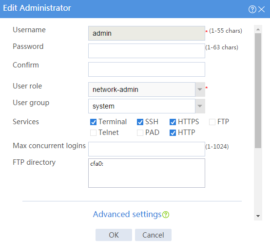
# In the dialog box that opens, select the HTTP service as shown in Figure 3.
Figure 3 Modifying administrator information

# Click OK.
Configuring user identification
1. Enable user identification:
# On the top navigation bar, click Objects.
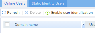
# From the navigation pane, select User > User Management > Online Users.
# On the Online Users tab, click Enable user identification.
Figure 4 Enabling user identification
2. Create RESTful server rest1:
# On the top navigation bar, click Objects.
# From the navigation pane, select User > Authentication > RESTful Server.
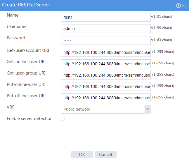
# Click Create.
# Configure the following parameters for the RESTful server:
¡ Set the server name to rest1, the username to admin, and the password to admin.
¡ Set the Get-user-account URI to http://192.168.100.244:8080/imcrs/ssm/imcuser/accessUser.
¡ Set the Get-online-user URI to http://192.168.100.244:8080/imcrs/ssm/imcuser/onlineUser.
¡ Set the Get-user-group URI to http://192.168.100.244:8080/imcrs/ssm/imcuser/accessUserGroup.
¡ Set the Put-online-user URI to http://192.168.100.244:8080/imcrs/ssm/imcuser/uploadOnlineUser.
¡ Set the Put-offline-user URI to http://192.168.100.244:8080/imcrs/ssm/imcuser/uploadOfflineUser.
|
|
For an IMC RESTful server, URIs are in a fixed format. You cannot modify any parameters in the above URIs except for the IP address. |
Figure 5 Creating a RESTful server
# Click OK.
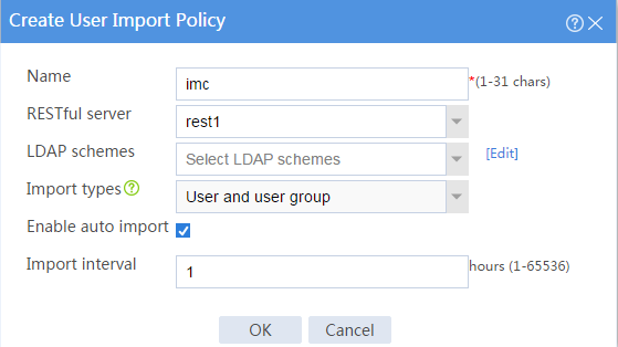
3. Create user import policy imc:
# On the top navigation bar, click Objects.
# From the navigation pane, select User > User Management > User Import Policies.
# Click Create.
# Configure parameters for the user import policy, as shown in Figure 6.
Figure 6 Creating a user import policy

# Click OK.
# After the firewall and the IMC server can communicate with each other, enter the User Import Policies page and select imc from the policy list. Then, click the Manually import identity users and Manually import online users icons to import the user accounts and online users on the IMC server to the firewall.
Figure 7 Importing user accounts and online users
![]()
Configuring security policies to ensure the network connectivity between the firewall and the IMC server
Perform the tasks in this section to ensure that the firewall can import identity user information from the IMC server.
.# On the top navigation bar, click Policies.
# From the navigation pane, select Security Policies > Security Policies.
# Click Create > Create a policy.
# Configure security policy trust-local to permit traffic from zone Trust to zone Local:
· Enter security policy name trust-local.
· Select source security zone Trust.
· Select destination security zone Local.
· Select type IPv4.
· Select action Permit.
· Use the default settings for other parameters.
# Click OK.
# Configure security policy local-trust in the same way you configure security policy trust-local to permit traffic from zone Local to zone Trust:
· Enter security policy name local-trust.
· Select source security zone Local.
· Select destination security zone Trust.
· Select type IPv4.
· Select action Permit.
· Use the default settings for other parameters.
# Configure security policy user10002 in the same way you configure security policy trust-local to permit user user10002 to access the FTP server and deny other users from accessing the FTP server:
· Enter security policy name user10002.
· Select source security zones Trust and DMZ.
· Select destination security zones Trust and DMZ.
· Select type IPv4.
· Select action Permit.
· Select user user10002.
· Use the default settings for other parameters.
# Configure security policy user10003 in the same way you configure security policy trust-local to permit user user10003 to access the Internet but denies users from the Internet from accessing the internal network:
· Enter security policy name user10003.
· Select source security zone Trust.
· Select destination security zone Untrust.
· Select type IPv4.
· Select action Permit.
· Select user user10003.
· Use the default settings for other parameters.
Adding managed devices to IMC
Add the router and firewall to IMC so that IMC can monitor and manage the devices.
1. Log in to IMC:
# Enter the IMC URL in the address bar of the Web browser. In this example, the URL is http://192.168.100.244:8080/imc/.
# Enter username admin and password admin.
2. Add the firewall to IMC:
# Click the Resource tab.
# From the navigation tree, select Resource Management > Add Device.
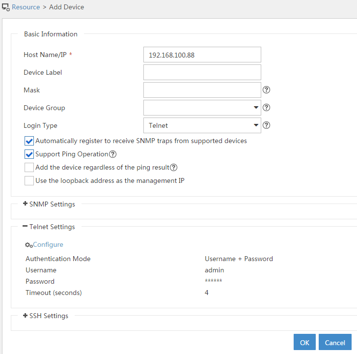
# On the page that opens, configure the parameters as shown in Figure 8:
¡ In the Telnet Settings area, set the username and password to admin.
¡ Use the default values for other parameters.
By default, the read-only SNMP community string is public and the read and write SNMP community string is private.
Figure 8 Adding the firewall to IMC
# Click OK.
# Add the router (192.168.100.90) to IMC in the same way you add the firewall to IMC.
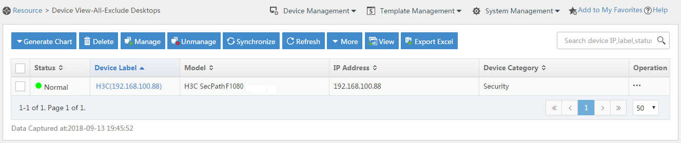
3. Modify NETCONF settings:
# Click the Resource tab.
# From the navigation tree, select View Management > Device View.
# Click the link in the Device Label column for the target device.
Figure 9 Device list
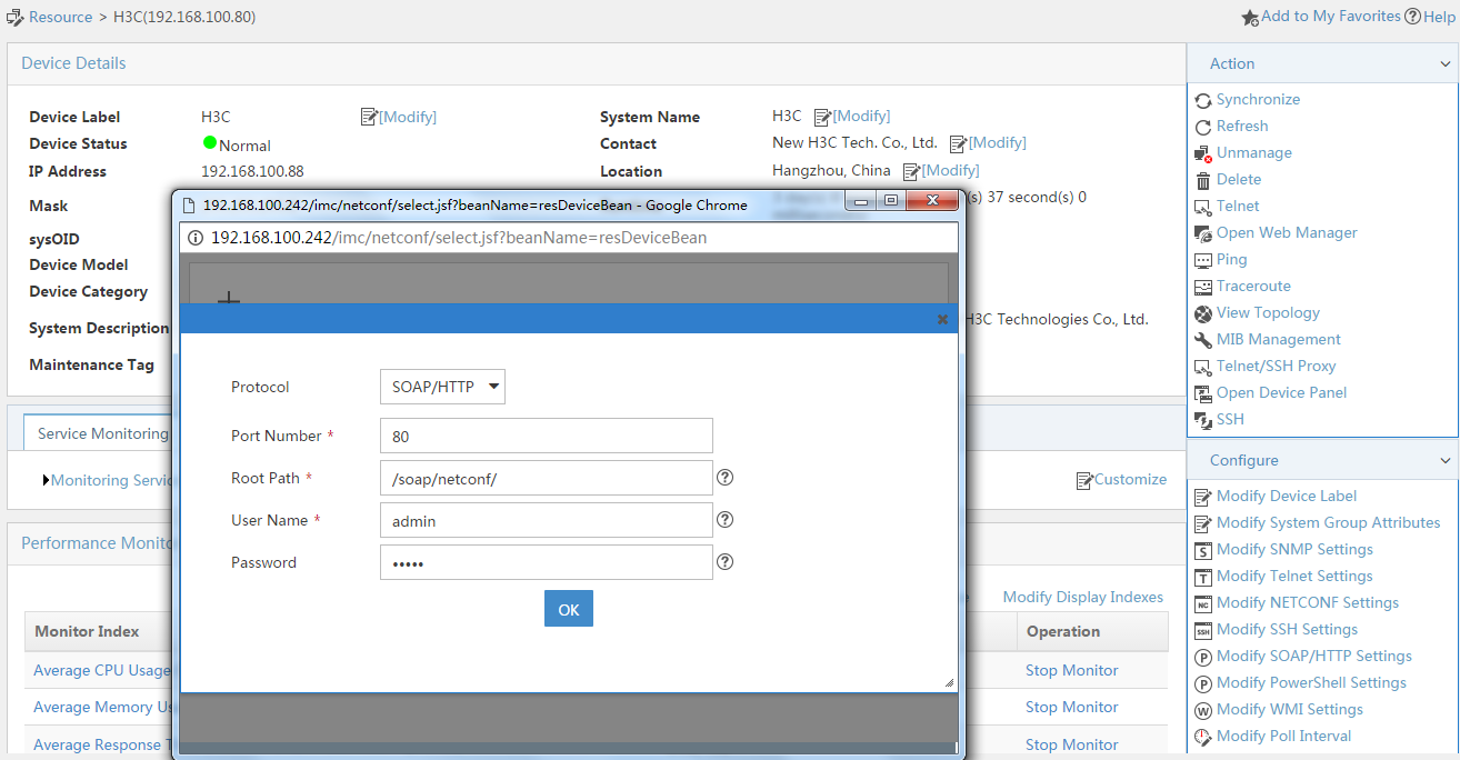
# In the right pane, click Configure > Modify NETCONF Settings.
# In the dialog box that opens, click the plus sign (+) to add a protocol as shown in Figure 10. In this example, set the username and password to admin.
Figure 10 Modifying NETCONF settings

# Click OK.
Configuring security services (IMC)
1. Synchronize security services from the firewall to the IMC server to ensure that the configuration and user information is consistent between the firewall and IMC server.
# Click the Service tab.
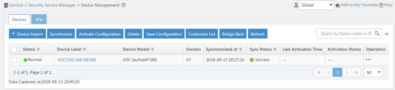
# From the navigation tree, select Security Service Manager > Device Management.
# On the Devices tab, the firewall is displayed in the device list, as shown in Figure 11.
Figure 11 Page for security device management (not synchronized)
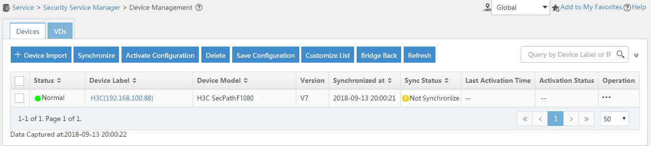
# Select the firewall in the device list and click Synchronize. You can view the synchronization status from the Sync Status column, as shown in Figure 12 and Figure 13.
The synchronization process might take a long time. Please wait.
Figure 12 Page for security device management (synchronizing)

Figure 13 Page for security device management (synchronization succeeded)

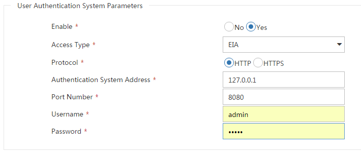
2. Configure user authentication system parameters and user notification parameters to ensure that the IMC server synchronizes user online and offline information to the firewall in real time.
# Click the Service tab.
# From the navigation tree, select Security Service Manager > Global Parameters.
# Configure the user authentication system parameters, as shown in Figure 14.
Select a protocol depending on the protocol of the portal authentication server. Make sure the username and password is the same as that used to log in to the IMC server.
Figure 14 Configuring user authentication system parameters

# Click OK.
# Click the User tab.
# From the navigation tree, select User Access Policy > Service Parameters > System Settings.
# Click the Configure icon for User Notification Parameters.
# On the page that opens, click Add.
# On the Add User Notification page, configure the parameters as shown in Figure 15. In this example, you can enter a shared key randomly.
Figure 15 Configuring user notification parameters
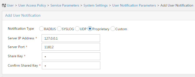
# Click OK.
Configuring the RADIUS server (IMC)
1. Add the router to the server as an access device:
# Click the User tab.
# From the navigation tree, select User Access Policy > Access Device Management > Access Device.
# Click Add.
# Set the shared key to admin, as shown in Figure 16.
# In the Device List area, click Select or Add Manually to add the device at 192.168.100.90 as an access device.
You must specify the source IP address of outgoing RADIUS packets on the router as the IP address of the access device on the server.
On the router, the source IP address is configured by using the nas-ip or radius nas-ip command. The IP address configured by using the nas-ip command has a higher priority than the IP address configured by using the radius nas-ip command. If no IP address is specified as the source IP address, the IP address of the packet outbound interface is used as the source IP address. In this example, the IP address of the packet outbound interface is used, which is 192.168.100.90.
Figure 16 Adding an access device
# Click OK.
2. Add an access policy:
# Click the User tab.
# From the navigation tree, select User Access Policy > Access Policy.
# Click Add.
# Set the access policy name to Portal, as shown in Figure 17.
Figure 17 Adding an access policy
# Click OK.
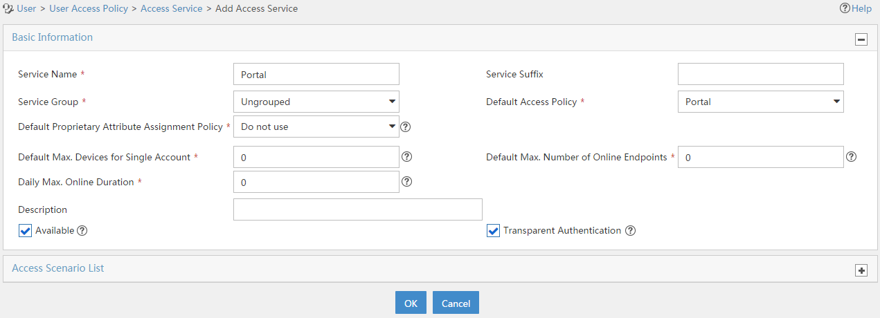
3. Add an access service:
# Select the User tab.
# From the navigation tree, select User Access Policy > Access Service.
# Click Add.
# On the Add Access Service page, configure the following parameters:
¡ Enter service name to Portal.
¡ Select Portal from the Default Access Policy list.
Figure 18 Adding an access service

# Click OK.
4. Add an access user:
# Click the User tab.
# From the navigation tree, select Access User > All Access Users.
# Click Add.
# On the Add Access User page, configure parameters as shown in Figure 19.
¡ Enter user in the User Name field.
¡ Enter user10001 in the Account Name field.
¡ Enter admin in the Password and Confirm Password fields.
¡ Select Portal in the Access Service area.
Figure 19 Adding an access user
# Click OK.
# Add user accounts user10002 and user10003 in the same way you add user account user10001.
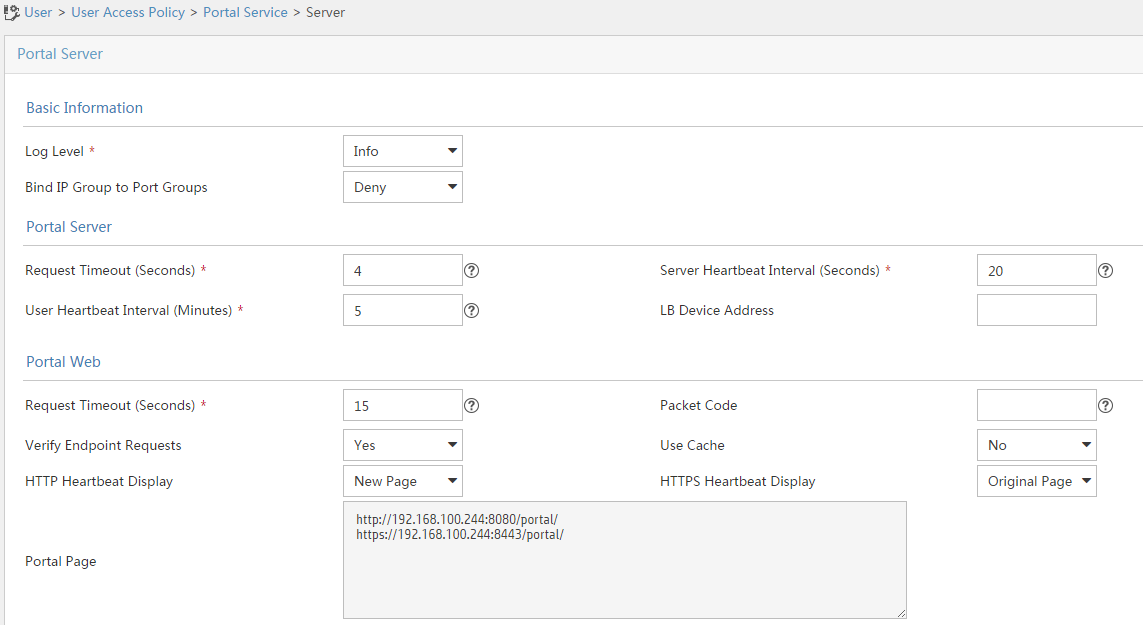
Configuring the portal server (IMC)
1. Configure the portal server:
# Click the User tab.
# From the navigation tree, select User Access Policy > Portal Service > Server.
# Configure the parameters in Figure 20 depending on the network conditions. In this example, the default values are used.
Figure 20 Configuring the portal server

# Click OK.
2. Add an IP group:
# Click the User tab.
# From the navigation tree, select User Access Policy > Portal Service > IP Group.
# Click Add.
# Configure parameters as shown in Figure 21.
# Click OK.
3. Add a portal device:
# Click the User tab.
# From the navigation tree, select User Access Policy > Portal Service > Device.
# Click Add.
# Set the shared key to admin and configure other parameters as shown in Figure 22.
Figure 22 Adding a portal device
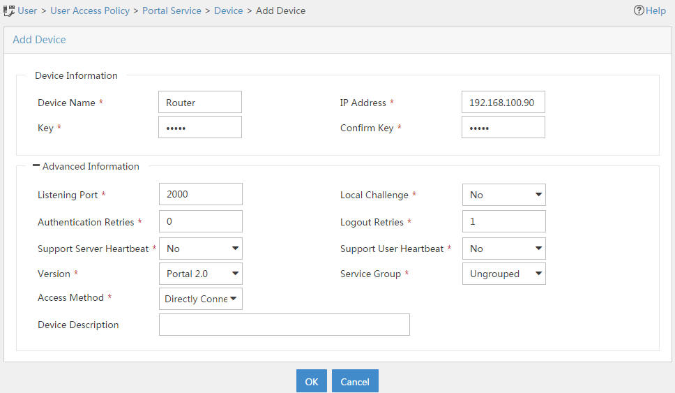
# Click OK.
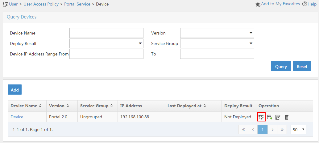
4. Associate the portal device with the IP group:
# Click the User tab.
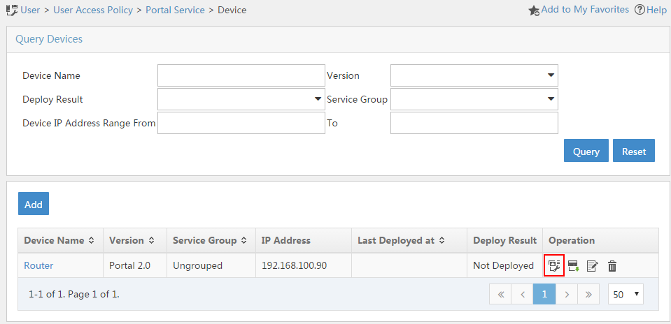
# From the navigation tree, select User Access Policy > Portal Service > Device.
# Click the Port Group icon in the Operation column for the router.
Figure 23 Device list
# On the page that opens, click Add.
# On the page that opens, configure a port group as shown in Figure 24.
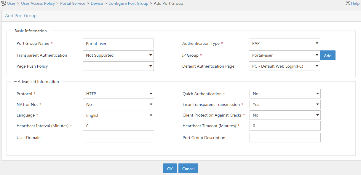
# Click OK.
Configuring the hosts
# Configure the IP address, network mask, and default gateway settings on each host. Make sure the hosts can communicate with the devices in the network. (Details not shown.)
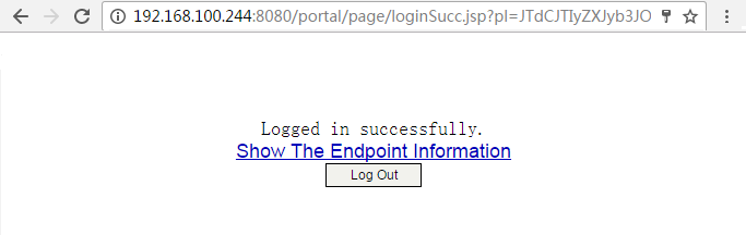
Verifying the configuration
1. On the hosts, verify that the users can pass portal authentication.
# Enter the URL of the portal Web server in the address bar of the Web browser to log in to the portal authentication page. In this example, the URL is http://192.168.100.244:8080/portal.
# Enter the username and password.
# Click Log In.
# Verify that the user has passed portal authentication.
Figure 25 Portal authentication success page

2. On the IMC server, verify that users user10001, user10002, and user10003 are in the online user list after they pass portal authentication. To view the online user list, click the User tab and select Access User > Online Users from the navigation tree.
3. On the firewall, display identity user information.
# Display information about all identity users.
[Device] display user-identity all user
User ID Username
0x2 user10001
0x3 user10002
0x4 user10003
# Display information about online identity user user10001.
[Device] display user-identity online-user null-domain name user10001
User name: user10001
IP : 20.2.1.11
MAC : 0011-95e4-4aa9
Type: Dynamic
Total 1 records matched.
# Display information about online identity user user10002.
[Device] display user-identity online-user null-domain name user10002
User name: user10002
IP : 20.2.1.12
MAC : 0011-95e4-4aa3
Type: Dynamic
Total 1 records matched.
# Display information about online identity user user10003.
[Device] display user-identity online-user null-domain name user10003
User name: user10003
IP : 20.2.1.13
MAC : 0011-95e4-4aa2
Type: Dynamic
Total 1 records matched.
4. Verify that the firewall can perform identity-based access control on the users:
# Verify that user user10001 cannot ping the FTP server.
C:\>ping 11.1.1.2
Pinging 11.1.1.2 with 32 bytes of data:
Request time out.
Request time out.
Request time out.
Request time out.
Ping statistics for 11.1.1.2:
Packets: Sent = 4, Received = 0, Lost = 4 (100% loss),
# Verify that user user10002 can ping the FTP server.
C:\>ping 11.1.1.2
Pinging 11.1.1.2 with 32 bytes of data:
Reply from 11.1.1.2: bytes=32 time=36ms TTL=253
Reply from 11.1.1.2: bytes=32 time<1ms TTL=253
Reply from 11.1.1.2: bytes=32 time<1ms TTL=253
Reply from 11.1.1.2: bytes=32 time<1ms TTL=253
Ping statistics for 11.1.1.2:
Packets: Sent = 4, Received = 4, Lost = 0 (0% loss),
Approximate round trip times in milli-seconds:
Minimum = 0ms, Maximum = 36ms, Average = 9ms
# When user user10002 pings the FTP server, verify that the firewall generates the following message:
[Device]%Nov 6 10:19:53:920 2017 H3C FILTER/6/FILTER_ZONE_EXECUTION_ICMP: -Context
=1; SrcZoneName(1025)=Trust;DstZoneName(1035)=DMZ;Type(1067)=ACL;SecurityPolicy(
1072)=user10002;RuleID(1078)=2;Protocol(1001)=ICMP;SrcIPAddr(1003)=20.2.1.12;Src
MacAddr(1021)=7425-8a37-b5f6;DstIPAddr(1007)=11.1.1.2;IcmpType(1062)=ECHO(8);Icm
pCode(1063)=0;MatchCount(1069)=1;Event(1048)=Permit;
# Verify that user user10003 can ping hosts in the Internet. In this example, the user pings the host at 12.1.1.2.
C:\>ping 12.1.1.2
Pinging 12.1.1.2 with 32 bytes of data:
Reply from 12.1.1.2: bytes=32 time=37ms TTL=253
Reply from 12.1.1.2: bytes=32 time<1ms TTL=253
Reply from 12.1.1.2: bytes=32 time<1ms TTL=253
Reply from 12.1.1.2: bytes=32 time<1ms TTL=253
Ping statistics for 12.1.1.2:
Packets: Sent = 4, Received = 4, Lost = 0 (0% loss),
Approximate round trip times in milli-seconds:
Minimum = 0ms, Maximum = 36ms, Average = 9ms
# When user user10003 pings the host in the Internet, verify that the firewall generates the following message:
[Device]%Nov 6 10:19:53:920 2017 H3C FILTER/6/FILTER_ZONE_EXECUTION_ICMP: -Context
=1; SrcZoneName(1025)=Trust;DstZoneName(1035)=Untrust;Type(1067)=ACL;SecurityPolicy(
1072)=user10003;RuleID(1078)=3;Protocol(1001)=ICMP;SrcIPAddr(1003)=20.2.1.13;Src
MacAddr(1021)=7425-8a37-b5f6;DstIPAddr(1007)=12.1.1.2;IcmpType(1062)=ECHO(8);Icm
pCode(1063)=0;MatchCount(1069)=1;Event(1048)=Permit;
Configuration files
Router
[Router] display current-configuration
#
interface GigabitEthernet0/0
port link-mode route
ip address 20.2.1.1 255.255.255.0
portal enable method direct
portal domain dm1
portal apply web-server newpt
#
interface GigabitEthernet0/1
port link-mode route
ip address 192.168.100.90 255.255.255.0
#
interface GigabitEthernet3/0
port link-mode route
combo enable copper
#
ip route-static 0.0.0.0 0 192.168.100.88
#
snmp-agent
snmp-agent local-engineid 800063A28074258A37B5F500000001
snmp-agent community write private
snmp-agent community read public
snmp-agent sys-info version all
#
radius scheme rs1
primary authentication 192.168.100.244
primary accounting 192.168.100.244
key authentication cipher $c$3$hhbEbD5Ycvw7VWqljAoMoU7hQRgcUjtg
user-name-format without-domain
#
domain dm1
authentication portal radius-scheme rs1
authorization portal radius-scheme rs1
accounting portal radius-scheme rs1
#
domain system
#
domain default enable system
#
local-user admin class manage
password hash $h$6$UbIhNnPevyKUwfpm$LqR3+yg1IjNct39MkOR0H0iQXLkYB3jMqM4vbAeoXOh
babIIFnjJPEGR00YiYA1Sz4LiY3FmEdru2fOLMb1shQ==
service-type telnet http
authorization-attribute user-role network-admin
#
portal web-server newpt
url http://192.168.100.244:8080/portal
#
portal server newpt
ip 192.168.100.244 key cipher $c$3$+UmaGOco7eHsjOqlrp8lI4eYe0A8NpYU
#
return
Device
[Device] display current-configuration
#
interface GigabitEthernet1/0/1
port link-mode route
ip address 192.168.100.88 255.255.255.0
#
interface GigabitEthernet1/0/2
port link-mode route
ip address 11.1.1.1 255.255.255.0
#
interface GigabitEthernet1/0/3
port link-mode route
ip address 12.1.1.1 255.255.255.0
#
security-zone name Trust
import interface GigabitEthernet1/0/1
#
security-zone name DMZ
import interface GigabitEthernet1/0/2
#
security-zone name Untrust
import interface GigabitEthernet1/0/3
#
line vty 0 63
authentication-mode scheme
user-role network-admin
#
ip route-static 0.0.0.0 0 12.1.1.2
ip route-static 20.2.1.0 24 192.168.100.90
#
snmp-agent
snmp-agent local-engineid 800063A280487ADA9593B700000001
snmp-agent community write private
snmp-agent community read public
snmp-agent sys-info version all
snmp-agent target-host trap address udp-domain 192.168.100.244 params securityn
ame public v2c
#
local-user admin class manage
password hash $h$6$UbIhNnPevyKUwfpm$LqR3+yg1IjNct39MkOR0H0iQXLkYB3jMqM4vbAeoXOh
babIIFnjJPEGR00YiYA1Sz4LiY3FmEdru2fOLMb1shQ==
service-type ssh telnet terminal http https
authorization-attribute user-role level-3
authorization-attribute user-role network-admin
authorization-attribute user-role network-operator
#
netconf soap http enable
netconf soap https enable
restful http enable
restful https enable
#
user-identity enable
user-identity user-account auto-import policy imc
#
user-identity restful-server rest1
login-name admin password cipher $c$3$phGy00HA6OP6pIpGI0KOKZEOPuLVbtt/
uri get-user-database http://192.168.100.244:8080/imcrs/ssm/imcuser/accessUser
uri get-user-group-database http://192.168.100.244:8080/imcrs/ssm/imcuser/acces
sUserGroup
uri get-online-user http://192.168.100.244:8080/imcrs/ssm/imcuser/onlineUser
uri put-online-user http://192.168.100.244:8080/imcrs/ssm/imcuser/uploadOnlineU
ser
uri put-offline-user http://192.168.100.244:8080/imcrs/ssm/imcuser/uploadOfflin
eUser
#
user-identity user-import-policy imc
account-update-interval 1
restful-server rest1
#
security-policy ip
rule 0 name trust-local
action pass
source-zone trust
destination-zone local
rule 1 name local-trust
action pass
source-zone local
destination-zone trust
rule 2 name user10002
action pass
logging enable
source-zone trust
source-zone dmz
destination-zone dmz
destination-zone trust
user user10002
rule 3 name user10003
action pass
logging enable
source-zone trust
destination-zone untrust
user user10003
#
return
Example: Configuring user identification for portal users that pass RADIUS authentication (non-RADIUS single sign-on)
Network configuration
As shown in Figure 26:
· Users user10001, user10002, and user10003 use static IP addresses, and they must pass portal authentication to access the network.
· Device is a firewall and acts as a NAS for the users to access the network. The NAS uses the RADIUS server to authenticate the users.
· The RADIUS server is installed with IMC components. For portal authentication, the server acts as both the portal authentication server and portal Web server.
· The RESTful server stores user account information. The server can synchronize user identity information to Device (the firewall).
· The firewall performs the following identity-based access control on the users that have passed portal authentication:
¡ Users user10001 and user10002 cannot access the Internet.
¡ User user10003 can access the Internet.
¡ Users from the Internet cannot access the hosts in the Trust and DMZ security zones.
Analysis
Figure 27 Analysis diagram
Software versions used
This configuration example was created and verified on the following software versions:
· F9345 of the F1060 device.
· Version 7.1.064, ESS 0701 of the MSR26-30 router.
The RADIUS and portal server is installed with IMC PLAT 7.3 (E0506), IMC UAM 7.3 (E0503), IMC CAMS 7.3 (E0501), and IMC SSM 7.3 (E0501).
Restrictions and guidelines
An IMC server logs off an online user only after it receives an accounting-stop request for that user. For the NAS to send accounting-stop requests to the server, you need to configure accounting settings in the authentication domain of the user on the NAS. However, you do not need to configure accounting parameters on the IMC server since accounting is not required.
Procedure
Configuring the router
Perform the tasks in this section to ensure the network connectivity of the router.
# Assign IP address 20.2.1.1 to GigabitEthernet 0/0.
<Router> system-view
[Router] interface gigabitethernet 0/0
[Router-GigabitEthernet0/0] ip address 20.2.1.1 255.255.255.0
[Router-GigabitEthernet0/0] quit
# Assign IP address 20.2.2.1 to GigabitEthernet 0/1.
[Router] interface gigabitethernet 0/1
[Router-GigabitEthernet0/1] ip address 20.2.2.1 255.255.255.0
[Router-GigabitEthernet0/1] quit
# Configure a default route to ensure that the router can reach the Internet.
[Router] ip route-static 0.0.0.0 0.0.0.0 20.2.2.2
Configuring Device (the firewall)
Configuring SNMP for the IMC server to monitor and manage the firewall
# Enable the SNMP agent.
<Device> system-view
[Device] snmp-agent
# Enable all SNMP versions, create the read-only community public and the read and write community private.
[Device] snmp-agent sys-info version all
[Device] snmp-agent community read public
[Device] snmp-agent community write private
Configuring NETCONF over SOAP for the IMC server to issue configuration to the firewall
# Enable NETCONF over SOAP over HTTP.
[Device] netconf soap http enable
# Enable NETCONF over SOAP over HTTPS.
[Device] netconf soap https enable
Enabling RESTful for the firewall to communicate with the IMC RESTful server
# Enable RESTful over HTTP.
[Device] restful http enable
# Enable RESTful over HTTPS.
[Device] restful https enable
Assigning IP addresses to interfaces and adding the interfaces to security zones
# On the top navigation bar, click Network.
# From the navigation pane, select Interface Configuration > Interfaces.
# Click the Edit icon for GE 1/0/1.
# In the dialog box that opens, configure the interface:
1. Select the DMZ security zone.
2. Click the IPv4 Address tab, and then enter the IP address and mask of the interface. In this example, enter 192.168.100.88/24.
3. Use the default settings for other parameters.
4. Click OK.
# Add GE 1/0/2 to the Trust security zone and set its IP address to 20.2.2.2/24 in the same way you configure GE 1/0/1.
# Add GE 1/0/3 to the Untrust security zone and set its IP address to 12.1.1.1/24 in the same way you configure GE 1/0/1.
Configuring routing
1. Configure a route to ensure that the firewall and the users can reach each other.
This step uses static routing as an example. To use dynamic routing, configure a dynamic routing protocol.
# On the top navigation bar, click Network.
# From the navigation pane, select Routing > Static Routing.
# On the IPv4 Static Routing tab, click Create.
# In the dialog box that opens, configure the IPv4 static route:
¡ Enter 20.2.1.0 in the Destination address field.
¡ Enter 24 in the Mask length field.
¡ Enter 20.2.2.1 as the next hop address in the Next hop field.
¡ Use the default settings for other parameters.
# Click OK.
2. Configure a default route to ensure that the firewall can reach the Internet.
This step uses static routing as an example. To use dynamic routing, configure a dynamic routing protocol.
# On the top navigation bar, click Network.
# From the navigation pane, select Routing > Static Routing.
# On the IPv4 Static Routing tab, click Create.
# In the dialog box that opens, configure the IPv4 static route:
¡ Enter 0.0.0.0 in the Destination address field.
¡ Enter 0 in the Mask length field.
¡ Enter 12.1.1.2 as the next hop address in the Next hop field.
Specify the IP address of the device that connects to the firewall in the Internet as the next hop address. In this example, the next hop address is 12.1.1.2.
¡ Use the default settings for other parameters.
# Click OK.
Assigning the HTTP service to administrator admin
# On the top navigation bar, click System.
# From the navigation pane, select Administrators > Administrators.
# Click the Edit icon for administrator admin.
# In the dialog box that opens, select the HTTP service as shown in Figure 28.
Figure 28 Modifying administrator information
# Click OK.
Configuring security policies to ensure the network connectivity between the firewall and the IMC server
Perform the tasks in this section to ensure that the firewall can import identity user information from the IMC server.
# On the top navigation bar, click Policies.
# From the navigation pane, select Security Policies > Security Policies.
# Click Create > Create a policy.
# Configure security policy dmz-local to permit traffic from zone DMZ to zone Local:
· Enter security policy name dmz-local.
· Select source security zone DMZ.
· Select destination security zone Local.
· Select type IPv4.
· Select action Permit.
· Use the default settings for other parameters.
# Click OK.
# Configure security policy local-dmz in the same way you configure security policy dmz-local to permit traffic from zone Local to zone DMZ:
· Enter security policy name local-dmz.
· Select source security zone Local.
· Select destination security zone DMZ.
· Select type IPv4.
· Select action Permit.
· Use the default settings for other parameters.
# Configure security policy trust-dmz in the same way you configure security policy dmz-local to permit traffic between zone Trust and zone DMZ. This task allows the NAS to send and receive AAA and portal authentication packets for the users and IMC server.
· Enter security policy name trust-dmz.
· Select source security zones Trust and DMZ.
· Select destination security zones Trust and DMZ.
· Select type IPv4.
· Select action Permit.
· Use the default settings for other parameters.
Configuring RADIUS scheme rs1
# On the top navigation bar, click Objects.
# From the navigation pane, select User > Authentication > RADIUS.
# Click Create.
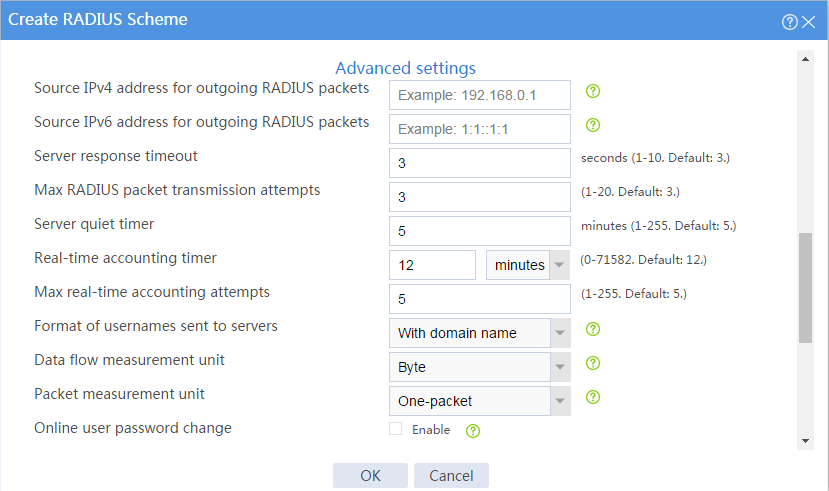
# In the dialog box that opens, create a RADIUS authentication server and a RADIUS accounting server and configure advanced settings, as shown in Figure 29, Figure 30, and Figure 31.
Figure 29 Creating a RADIUS scheme (authentication servers)
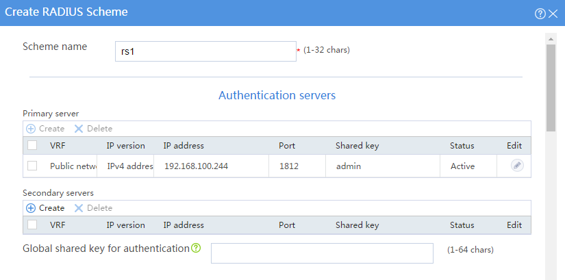
Figure 30 Creating a RADIUS scheme (accounting servers)
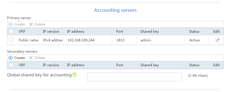
Figure 31 Creating a RADIUS scheme (advanced settings)
# Click OK.
Configuring authentication domain dm1
# On the top navigation bar, click Objects.
# From the navigation pane, select User > Authentication > ISP Domains.
# Click Create.
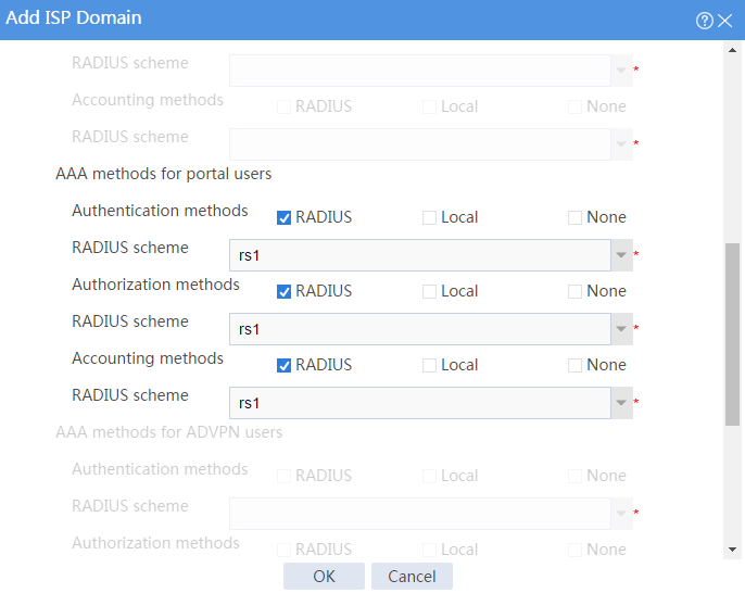
# In the dialog box that opens, configure the access types and the AAA methods for portal users, as shown in Figure 32 and Figure 33.
Figure 32 Adding ISP domain dm1 (access types)
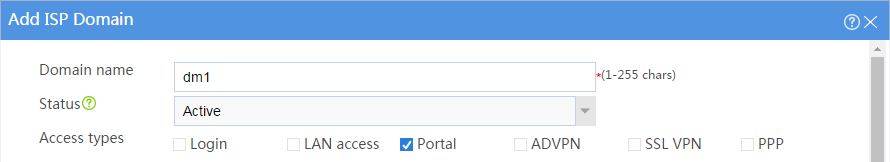
Figure 33 Adding ISP domain dm1 (AAA methods for portal users)
# Click OK.
Configuring portal authentication
1. Configuring the portal authentication server:
# On the top navigation bar, click Objects.
# From the navigation pane, select User > Access Control > Portal.
# On the Portal Authentication Servers tab, click Create.
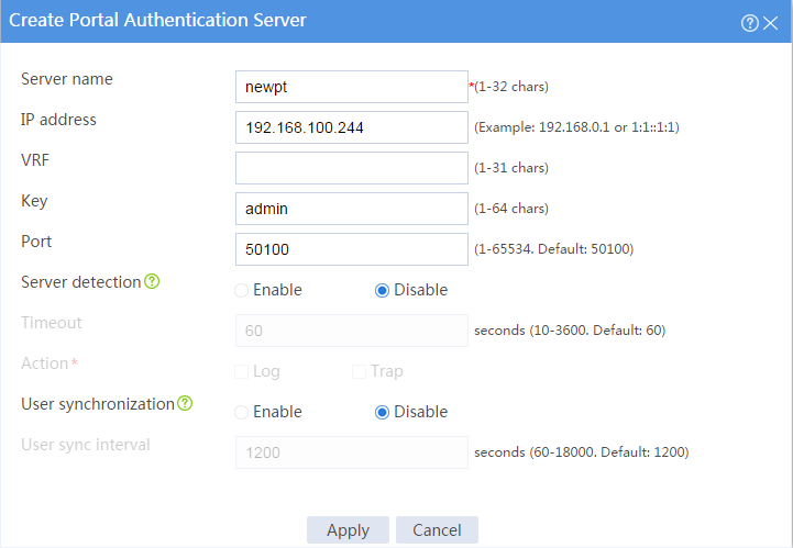
# In the dialog box that opens, configure the portal authentication server:
¡ Enter server name newpt.
¡ Set the IP address to 192.168.100.244.
¡ Enter key admin.
¡ Set the port to 50100.
Figure 34 Creating a portal authentication server
# Click OK.
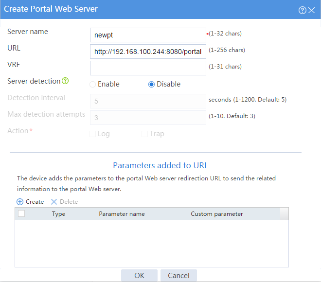
2. Configure the portal Web server:
# On the top navigation bar, click Objects.
# From the navigation pane, select User > Access Control > Portal.
# Click the Portal Web Servers tab.
# Click Create.
# In the dialog box that opens, configure the server name and URL, as shown in Figure 35. In this example, the URL is http://192.168.100.244:8080/portal.
Figure 35 Creating a portal Web server
# Click OK.
3. Configure an interface portal policy and enable IPv4 portal on GE 1/0/2:
# On the top navigation bar, click Objects.
# From the navigation pane, select User > Access Control > Portal.
# Click the Interface Portal Policies tab.
# Click Create.
# In the dialog box that opens, configure the interface portal policy, as shown in Figure 36.
Figure 36 Creating an interface portal policy
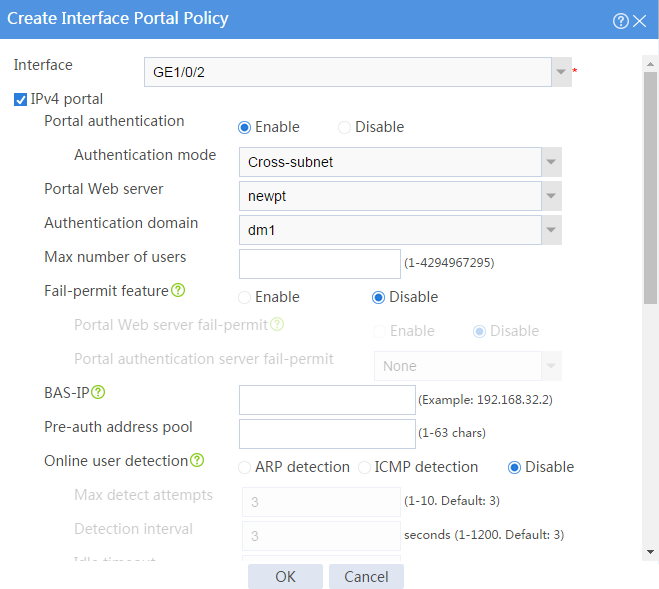
# Click OK.
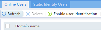
Configuring user identification
1. Enable user identification:
# On the top navigation bar, click Objects.
# From the navigation pane, select User > User Management > Online Users.
# On the Online Users tab, click Enable user identification.
Figure 37 Enabling user identification
2. Create RESTful server rest1:
# On the top navigation bar, click Objects.
# From the navigation pane, select User > Authentication > RESTful Server.
# Click Create.
# In the dialog box that opens, configure the following parameters for the RESTful server:
¡ Enter server name rest1.
¡ Enter username admin.
¡ Enter password admin.
¡ Set the Get-user-account URI to http://192.168.100.244:8080/imcrs/ssm/imcuser/accessUser.
¡ Set the Get-user-group URI to http://192.168.100.244:8080/imcrs/ssm/imcuser/accessUserGroup.
|
|
For an IMC RESTful server, URIs are in a fixed format. You cannot modify any parameters in the above URIs except for the IP address. |
Figure 38 Creating the RESTful server
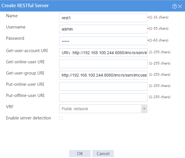
# Click OK.
3. Create user import policy imc:
# On the top navigation bar, click Objects.
# From the navigation pane, select User > User Management > User Import Policies.
# Click Create.
# In the dialog box that opens, configure parameters for the user import policy, as shown in Figure 39.
Figure 39 Creating user import policy imc
# Click OK.
# After the firewall and the IMC server can communicate with each other, enter the User Import Policies page and click the Manually import identity users icon for policy imc to import the user accounts on the IMC server to the firewall.
Figure 40 Importing user accounts
![]()
Configuring a security policy to permit user user10003 to access the Internet
Perform this task to create a security policy to permit user user10003 to access the Internet and deny users from the Internet from accessing the internal network.
# On the top navigation bar, click Policies.
# From the navigation pane, select Security Policies > Security Policies.
# Click Create > Create a policy.
# In the dialog box that opens, configure the security policy:
· Enter security policy name user10003.
· Select source security zone Trust.
· Select destination security zone Untrust.
· Select type IPv4.
· Select action Permit.
· Select user user10003.
· Use the default settings for other parameters.
# Click OK.
Adding the firewall to IMC
# Add the firewall to IMC for IMC to monitor and manage the firewall.
1. Log in to IMC:
# Enter the IMC URL in the address bar of the Web browser. In this example, the URL is http://192.168.100.244:8080/imc/.
# Enter username admin and password admin.
2. Add the firewall to IMC:
# Click the Resource tab.
# From the navigation tree, select Resource Management > Add Device.
# On the page that opens, configure parameters as shown in Figure 41:
¡ Set the username and password to admin in the Telnet Settings area.
¡ Use the default values for other parameters.
By default, the read-only SNMP community string is public and the read and write SNMP community string is private.
Figure 41 Adding the firewall to IMC

# Click OK.
3. Modify NETCONF settings:
# Click the Resource tab.
# From the navigation tree, select View Management > Device View.
# Click the link in the Device Label column for the target device.
Figure 42 Device list

# In the right pane, click Configure > Modify NETCONF Settings.
# In the dialog box that opens, click the plus sign (+) to add a protocol as shown in Figure 43.
In this example, set the username and password to admin.
Figure 43 Modifying NETCONF settings
# Click OK.
Configuring security services (IMC)
1. Synchronize security services from the firewall to the IMC server to ensure that the configuration and user information is consistent between the firewall and IMC server.
# Click the Service tab.
# From the navigation tree, select Security Service Manager > Device Management.
# On the Devices tab, the firewall is displayed in the device list, as shown in Figure 44.
Figure 44 Page for security device management (not synchronized)

# Select the firewall in the device list and click Synchronize. You can view the synchronization status from the Sync Status column, as shown in Figure 45 and Figure 46.
The synchronization process might take a long time. Please wait.
Figure 45 Page for security device management (synchronizing)

Figure 46 Page for security device management (synchronization succeeded)
2. Configure user authentication system parameters and user notification parameters to ensure that the IMC server synchronizes user online and offline information to the firewall in real time.
# Click the Service tab.
# From the navigation tree, select Security Service Manager > Global Parameters.
# Configure the user authentication system parameters, as shown in Figure 47.
Select a protocol depending on the protocol of the portal authentication server. Make sure the username and password is the same as that used to log in to the IMC server.
Figure 47 Configuring user authentication system parameters
# Click OK.
# Click the User tab.
# From the navigation tree, select User Access Policy > Service Parameters > System Settings.
# Click the Configure icon for User Notification Parameters.
# On the page that opens, click Add.
# On the Add User Notification page, configure the parameters as shown in Figure 48. In this example, you can enter a shared key randomly.
Figure 48 Configuring user notification parameters

# Click OK.
Configuring the RADIUS server (IMC)
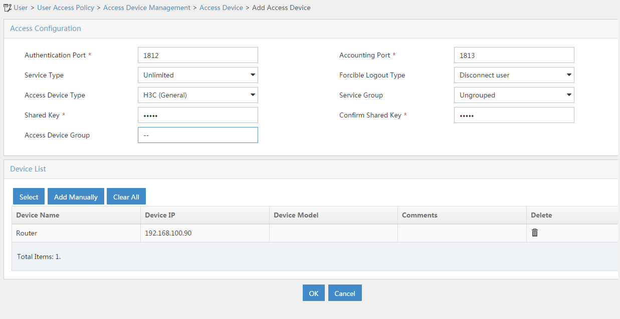
1. Add the firewall to the IMC server as an access device:
# Click the User tab.
# From the navigation tree, select User Access Policy > Access Device Management > Access Device.
# Click Add.
# In the Access Configuration area, set the shared key to admin, as shown in Figure 49.
# In the Device List area, click Select or Add Manually to add the device at 192.168.100.88 as an access device.
You must specify the source IP address of outgoing RADIUS packets on the firewall as the IP address of the access device on the server.
On the firewall, the source IP address is configured by using the nas-ip or radius nas-ip command. The IP address configured by using the nas-ip command has a higher priority than the IP address configured by using the radius nas-ip command. If no IP address is specified as the source IP address, the IP address of the packet outbound interface is used as the source IP address. In this example, the IP address of the packet outbound interface is used, which is 192.168.100.88.
Figure 49 Adding an access device

# Click OK.
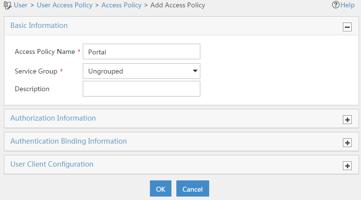
2. Add an access policy:
# Click the User tab.
# From the navigation tree, select User Access Policy > Access Policy.
# Click Add.
# On the Add Access Policy page, set the access policy name to Portal, as shown in Figure 50.
Figure 50 Adding an access policy

# Click OK.
3. Add an access service:
# Select the User tab.
# From the navigation tree, select User Access Policy > Access Service.
# Click Add.
# On the Add Access Service page, set the service name to Portal and select Portal from the Default Access Policy list.
Figure 51 Adding an access service
# Click OK.
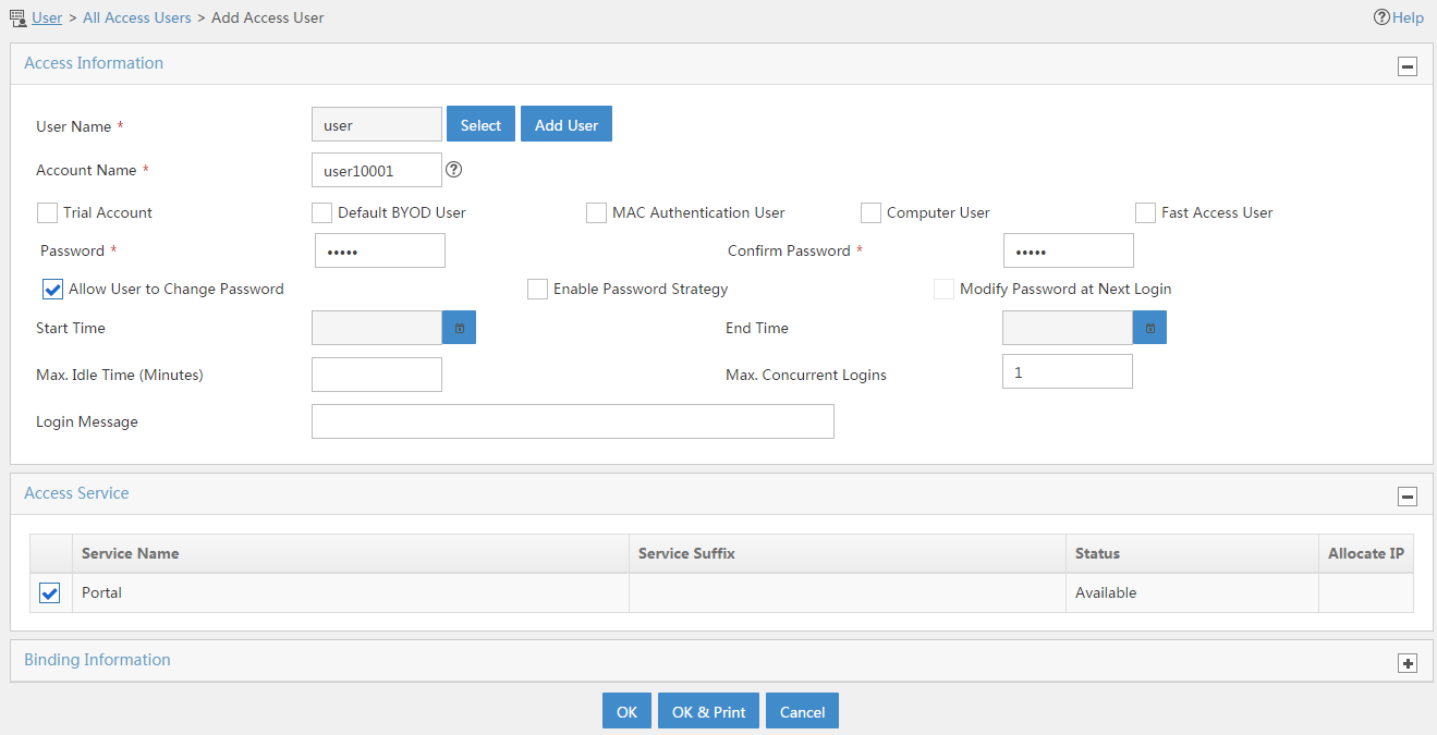
4. Add an access user:
# Click the User tab.
# From the navigation tree, select Access User > All Access Users.
# Click Add.
# On the Add Access User page, configure parameters as shown in Figure 52.
¡ Enter user in the User Name field.
¡ Enter user10001 in the Account Name field.
¡ Enter admin in the Password and Confirm Password fields.
¡ Select Portal in the Access Service area.
Figure 52 Adding an access user

# Click OK.
# Add user accounts user10002 and user10003 in the same way you add user account user10001.
Configuring the portal server (IMC)
1. Configure the portal server:
# Click the User tab.
# From the navigation tree, select User Access Policy > Portal Service > Server.
# Configure the parameters in Figure 53 depending on the network conditions. In this example, the default values are used.
Figure 53 Portal server configuration
# Click OK.
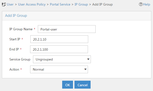
2. Add an IP group:
# Click the User tab.
# From the navigation tree, select User Access Policy > Portal Service > IP Group.
# Click Add.
# On the Add IP Group page, configure the IP group parameters as shown in Figure 54.

# Click OK.
3. Add a portal device:
# Click the User tab.
# From the navigation tree, select User Access Policy > Portal Service > Device.
# Click Add.
# On the Add Device page, set the key to admin and configure other parameters as shown in Figure 55.
Figure 55 Adding portal device configuration

# Click OK.
4. Associate the portal device with the IP group:
# Click the User tab.
# From the navigation tree, select User Access Policy > Portal Service > Device.
# Click the Port Group icon in the Operation column for the firewall
Figure 56 Device list
# On the page that opens, click Add.
# On the page that opens, configure a port group as shown in Figure 57.

# Click OK.
Configuring the hosts
# Configure the IP address, network mask, and default gateway settings for each host. Make sure the hosts can communicate with the devices in the network. (Details not shown.)
Verifying the configuration
1. On the hosts, verify that the users can pass portal authentication.
# Enter the URL of the portal Web server in the address bar of the Web browser to log in to the portal authentication page. In this example, the URL is http://192.168.100.244:8080/portal.
# Enter the username and password.
# Click Log In.
# Verify that the user has passed portal authentication.
Figure 58 Portal authentication success page
2. On the IMC server, verify that users user10001, user10002, and user10003 are in the online user list after they pass portal authentication. To view the online user list, click the User tab and select Access User > Online Users from the navigation tree.
3. On the firewall, display information about all portal users.
[Device] display portal user all
Total portal users: 3
Username: user10001
Portal server: newpt
State: Online
VPN instance: N/A
MAC IP VLAN Interface
0011-95e4-4aa9 20.2.1.13 -- GigabitEthernet1/0/2
Authorization information:
DHCP IP pool: N/A
User profile: N/A
Session group profile: N/A
ACL number: N/A
Inbound CAR: N/A
Outbound CAR: N/A
Username: user10002
Portal server: newpt
State: Online
VPN instance: N/A
MAC IP VLAN Interface
0011-95e4-4aa3 20.2.1.13 -- GigabitEthernet1/0/2
Authorization information:
DHCP IP pool: N/A
User profile: N/A
Session group profile: N/A
ACL number: N/A
Inbound CAR: N/A
Outbound CAR: N/A
Username: user10003
Portal server: newpt
State: Online
VPN instance: N/A
MAC IP VLAN Interface
0011-95e4-4aa2 20.2.1.13 -- GigabitEthernet1/0/2
Authorization information:
DHCP IP pool: N/A
User profile: N/A
Session group profile: N/A
ACL number: N/A
Inbound CAR: N/A
Outbound CAR: N/A
4. On the firewall, display identity user information.
# Display information about all identity users.
[Device] display user-identity all user
User ID Username
0x2 user10001
0x3 user10002
0x4 user10003
# Display information about online identity user user10001.
[Device] display user-identity online-user null-domain name user10001
User name: user10001
IP : 20.2.1.11
MAC : 0011-95e4-4aa9
Type: Dynamic
Total 1 records matched.
# Display information about online identity user user10002.
[Device] display user-identity online-user null-domain name user10002
User name: user10002
IP : 20.2.1.12
MAC : 0011-95e4-4aa3
Type: Dynamic
Total 1 records matched.
# Display information about online identity user user10003.
[Device] display user-identity online-user null-domain name user10003
User name: user10003
IP : 20.2.1.13
MAC : 0011-95e4-4aa2
Type: Dynamic
Total 1 records matched.
5. Verify that the firewall can perform identity-based access control on the users:
# Verify that user user10001 cannot ping any host in the Internet. In this example, the user pings the host at 12.1.1.2.
C:\>ping 12.1.1.2
Pinging 12.1.1.2 with 32 bytes of data:
Request time out.
Request time out.
Request time out.
Request time out.
Ping statistics for 12.1.1.2:
Packets: Sent = 4, Received = 0, Lost = 4 (100% loss),
# Verify that user user10003 can ping hosts in the Internet. In this example, the user pings the host at 12.1.1.2.
C:\>ping 12.1.1.2
Pinging 12.1.1.2 with 32 bytes of data:
Reply from 12.1.1.2: bytes=32 time=36ms TTL=253
Reply from 12.1.1.2: bytes=32 time<1ms TTL=253
Reply from 12.1.1.2: bytes=32 time<1ms TTL=253
Reply from 12.1.1.2: bytes=32 time<1ms TTL=253
Ping statistics for 12.1.1.2:
Packets: Sent = 4, Received = 4, Lost = 0 (0% loss),
Approximate round trip times in milli-seconds:
Minimum = 0ms, Maximum = 36ms, Average = 9ms
# When user user10003 pings the host in the Internet, the firewall generates the following message:
[Device]%Nov 6 10:19:53:920 2017 H3C FILTER/6/FILTER_ZONE_EXECUTION_ICMP: -Context
=1; SrcZoneName(1025)=Trust;DstZoneName(1035)=Untrust;Type(1067)=ACL;SecurityPolicy(
1072)=user10003;RuleID(1078)=3;Protocol(1001)=ICMP;SrcIPAddr(1003)=20.2.1.13;Src
MacAddr(1021)=7425-8a37-b5f6;DstIPAddr(1007)=12.1.1.2;IcmpType(1062)=ECHO(8);Icm
pCode(1063)=0;MatchCount(1069)=1;Event(1048)=Permit;
Configuration files
Router
[Router] display current-configuration
#
interface GigabitEthernet0/0
port link-mode route
ip address 20.2.1.1 255.255.255.0
#
interface GigabitEthernet0/1
port link-mode route
ip address 20.2.2.1 255.255.255.0
#
interface GigabitEthernet3/0
port link-mode route
combo enable copper
#
ip route-static 0.0.0.0 0 20.2.2.2
#
snmp-agent
snmp-agent local-engineid 800063A28074258A37B5F500000001
snmp-agent community write private
snmp-agent community read public
snmp-agent sys-info version all
#
local-user admin class manage
password hash $h$6$UbIhNnPevyKUwfpm$LqR3+yg1IjNct39MkOR0H0iQXLkYB3jMqM4vbAeoXOh
babIIFnjJPEGR00YiYA1Sz4LiY3FmEdru2fOLMb1shQ==
service-type telnet http
authorization-attribute user-role network-admin
#
return
Device
[Device] display current-configuration
#
interface GigabitEthernet1/0/1
port link-mode route
ip address 192.168.100.88 255.255.255.0
#
interface GigabitEthernet1/0/2
port link-mode route
ip address 20.2.2.2 255.255.255.0
portal enable method direct
portal domain dm1
portal apply web-server newpt
#
interface GigabitEthernet1/0/3
port link-mode route
ip address 12.1.1.1 255.255.255.0
#
security-zone name Trust
import interface GigabitEthernet1/0/2
#
security-zone name DMZ
import interface GigabitEthernet1/0/1
#
security-zone name Untrust
import interface GigabitEthernet1/0/3
#
line vty 0 63
authentication-mode scheme
user-role network-admin
#
ip route-static 0.0.0.0 0 12.1.1.2
ip route-static 20.2.1.0 24 20.2.2.1
#
snmp-agent
snmp-agent local-engineid 800063A280487ADA9593B700000001
snmp-agent community write private
snmp-agent community read public
snmp-agent sys-info version all
snmp-agent target-host trap address udp-domain 192.168.100.244 params securityn
ame public v2c
#
radius scheme rs1
primary authentication 192.168.100.244
primary accounting 192.168.100.244
key authentication cipher $c$3$hhbEbD5Ycvw7VWqljAoMoU7hQRgcUjtg
user-name-format without-domain
#
domain dm1
authentication portal radius-scheme rs1
authorization portal radius-scheme rs1
accounting portal radius-scheme rs1
#
domain system
#
domain default enable system
#
local-user admin class manage
password hash $h$6$UbIhNnPevyKUwfpm$LqR3+yg1IjNct39MkOR0H0iQXLkYB3jMqM4vbAeoXOh
babIIFnjJPEGR00YiYA1Sz4LiY3FmEdru2fOLMb1shQ==
service-type ssh telnet terminal http https
authorization-attribute user-role level-3
authorization-attribute user-role network-admin
authorization-attribute user-role network-operator
#
portal web-server newpt
url http://192.168.100.244:8080/portal
#
portal server newpt
ip 192.168.100.244 key cipher $c$3$+UmaGOco7eHsjOqlrp8lI4eYe0A8NpYU
#
netconf soap http enable
netconf soap https enable
restful http enable
restful https enable
#
user-identity enable
user-identity user-account auto-import policy imc
#
user-identity restful-server rest1
login-name admin password cipher $c$3$phGy00HA6OP6pIpGI0KOKZEOPuLVbtt/
uri get-user-database http://192.168.100.244:8080/imcrs/ssm/imcuser/accessUser
uri get-user-group-database http://192.168.100.244:8080/imcrs/ssm/imcuser/acces
sUserGroup
uri get-online-user http://192.168.100.244:8080/imcrs/ssm/imcuser/onlineUser
uri put-online-user http://192.168.100.244:8080/imcrs/ssm/imcuser/uploadOnlineU
ser
uri put-offline-user http://192.168.100.244:8080/imcrs/ssm/imcuser/uploadOfflin
eUser
#
user-identity user-import-policy imc
account-update-interval 1
restful-server rest1
#
security-policy ip
rule 0 name dmz-local
action pass
source-zone dmz
destination-zone local
rule 1 name local-dmz
action pass
source-zone local
destination-zone dmz
rule 2 name trust-dmz
action pass
source-zone trust
source-zone dmz
destination-zone dmz
destination-zone trust
rule 3 name user10003
action pass
logging enable
source-zone trust
destination-zone untrust
user user10003
#
return