- Table of Contents
-
- 08-Configuration Examples
- 01-Web Login Configuration Examples
- 02-Internet Access Through a Static IP Address Configuration Examples
- 03-Internet access through PPPoE configuration examples
- 04-Signature Library Upgrade Configuration Examples
- 04-Software Upgrade Examples(only for F50X0-D and F5000-AK5X5 firewalls)
- 05-Software Upgrade Examples
- 06-Static routing configuration examples
- 07-OSPF configuration examples
- 08-BGP configuration examples
- 09-RIP configuration examples
- 10-DHCP configuration examples
- 11-DNS configuration examples
- 12-Object Group Configuration Examples
- 13-Public key management configuration examples
- 14-Security Policy Configuration Examples
- 15-Attack defense configuration examples
- 16-Connection Limit Configuration Examples
- 17-IPS Configuration Examples
- 18-URL Filtering Configuration Examples
- 19-Anti-Virus Configuration Examples
- 20-Data Filtering Configuration Examples
- 21-File Filtering Configuration Examples
- 22-APR-Based Security Policy Configuration Examples
- 23-Bandwidth Management Configuration Examples
- 24-NAT configuration examples
- 25-NAT hairpin configuration examples
- 26-IPsec configuration examples
- 27-SSL VPN configuration examples
- 28-Server Load Balancing Configuration Examples
- 29-Outbound Link Load Balancing Configuration Examples
- 30-Inbound Link Load Balancing Configuration Examples
- 31-Transparent DNS Proxy Configuration Examples
- 32-Context Configuration Examples
- 32-Context Configuration Examples(only for F50X0-D and F5000-AK5X5 firewalls)
- 33-IRF configuration examples
- 34-High Availability Group Configuration Examples
- 35-NAT Flow Logging Configuration Examples
- 36-User identification configuration examples
- 37-Server Connection Detection Configuration Examples
- 38-IP Reputation Configuration Examples
- 39-NPTv6 Configuration Examples
- 40-SSL Decryption Configuration Examples
- 41-MAC Address Learning Through a Layer 3 Device Configuration Examples
- 42-WAF Configuration Examples
- 43-NetShare Control Configuration Examples
- 44-4G Configuration Examples
- 45-WLAN Configuration Examples
- Related Documents
-
| Title | Size | Download |
|---|---|---|
| 24-NAT configuration examples | 376.03 KB |
The following information describes NAT configuration examples.
The following NAT translation methods are supported:
Static NAT
Static NAT creates a fixed mapping between a private address and a public address. It supports connections initiated from internal users to external network and from external users to the internal network. Static NAT applies to regular communications.
Dynamic NAT
Dynamic NAT uses an address pool to translate addresses. It applies to the scenario where a large number of internal users access the external network.
NAT Server
The NAT Server feature maps a public address and port number to the private IP address and port number of an internal server. This feature allows servers in the private network to provide services for external users.
NAT444 port block
NAT444 provides carrier-grade NAT by unifying the NAT444 gateway, AAA server, and log server. NAT444 introduces a second layer of NAT on the carrier side, with few changes on the customer side and the application server side. With port block assignment, NAT444 supports user tracking. It has become a preferred solution for carriers in transition to IPv6.
This document is not restricted to specific software or hardware versions. Procedures and information in the examples might be slightly different depending on the software or hardware version of the device.
The configuration examples were created and verified in a lab environment, and all the devices were started with the factory default configuration. When you are working on a live network, make sure you understand the potential impact of every command on your network.
The following information is provided based on the assumption that you have basic knowledge of NAT.
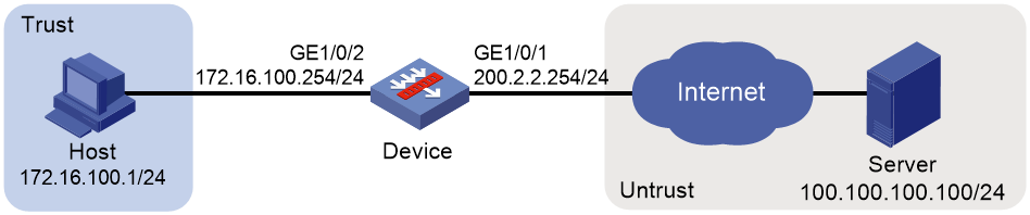
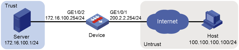
Network configuration
As shown in Figure 1, configure static NAT to allow the host at 172.16.100.1/24 to access the server at 100.100.100.100/24 on the Internet by using public IP address 200.2.2.254/24.
Software versions used
This configuration example was created and verified on F9345 of the F1060 device.
Procedure
1. Assign IP addresses to interfaces and add the interfaces to security zones.
# On the top navigation bar, click Network.
# From the navigation pane, select Interface Configuration > Interfaces.
# Click the Edit icon for GE 1/0/1.
# In the dialog box that opens, configure the interface:
a. Select the Untrust security zone.
b. On the IPv4 Address tab, enter the IP address and mask of the interface. In this example, enter 200.2.2.254/24.
c. Click OK.
# Add GE 1/0/2 to the Trust security zone and set its IP address to 172.16.100.254/24 in the same way you configure GE 1/0/1.
2. Configure settings for routing.
This example configures a static route. If dynamic routes are required, configure a dynamic routing protocol.
# On the top navigation bar, click Network.
# From the navigation pane, select Routing > Static Routing.
# On the IPv4 Static Routing tab, click Create.
# In the dialog box that opens, configure a static route to permit packets from the device to the server:
a. Specify the IP address of the server as the destination IP. In this example, the address is 100.100.100.100.
b. Enter the mask length. In this example, enter 24.
c. Specify the next-hop address as 200.2.2.253.
d. Click OK.
3. Configure a security policy.
# On the top navigation bar, click Policies.
# From the navigation pane, select Security Policies > Security Policies.
# Click Create and click Create a policy.
# In the dialog box that opens, configure policy parameters as follows:
a. Enter a policy name. In this example, the name is Secpolicy.
b. Select the source zone. In this example, the source zone is Trust.
c. Select the destination zone. In this example, the destination zone is Untrust.
d. Select IPv4 as the type.
e. Select Permit as the action.
f. Specify the IP address of the host as the source IPv4 address. In this example, the address is 172.16.100.1.
g. Specify the IP address of the server as the destination IPv4 address. In this example, the address is 100.100.100.100.
h. Click OK.
4. Create a static NAT mapping.
# On the top navigation bar, click Policies.
# From the navigation pane, select NAT > Static NAT > Policy Configuration.
# Click Create.
# Create a static NAT mapping, as shown in Figure 2.
Figure 2 Creating a static NAT mapping
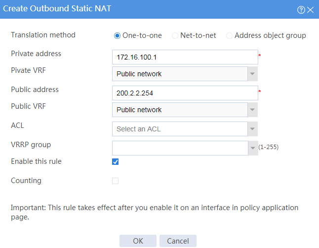
# Click OK.
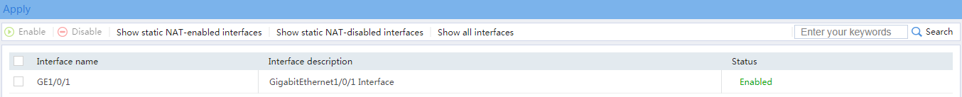
5. Apply the static NAT mapping.
# On the top navigation bar, click Policies.
# From the navigation pane, select NAT > Static NAT > Apply Policy.
# Select GE 1/0/1 and click Enable. The mapping has been applied to the interface, as shown in Figure 3.
Figure 3 Applying the static NAT mapping
Verifying the configuration
1. Verify that the host can successfully ping the server on the external network.
C:\Users\abc>ping 100.100.100.100
Pinging host.com [100.100.100.100] with 32 bytes of data:
Reply from 100.100.100.100: bytes=32 time<1ms TTL=253
Reply from 100.100.100.100: bytes=32 time<1ms TTL=253
Reply from 100.100.100.100: bytes=32 time<1ms TTL=253
Reply from 100.100.100.100: bytes=32 time<1ms TTL=253
Ping statistics for 100.100.100.100:
Packets: Sent = 4, Received = 4, Lost = 0 (0% loss),
Approximate round trip times in milli-seconds:
Minimum = 0ms, Maximum = 0ms, Average = 0ms
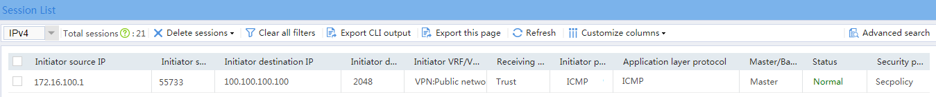
2. Verify that a NAT session is generated when the host accesses the server.
# On the top navigation bar, click Monitor.
# From the navigation pane, select Sessions.
Figure 4 Session list

Example: Configuring NO-PAT for dynamic NAT
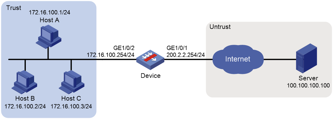
Network configuration
As shown in Figure 5, the company has public addresses 200.2.2.1/24 to 200.2.2.3/24. Configure NO-PAT translation to enable hosts in the internal network to access the server on the Internet.
Software versions used
This configuration example was created and verified on F9345 of the F1060 device.
Procedure
1. Assign IP addresses to interfaces and add the interfaces to security zones.
# On the top navigation bar, click Network.
# From the navigation pane, select Interface Configuration > Interfaces.
# Click the Edit icon for GE 1/0/1.
# In the dialog box that opens, configure the interface:
a. Select the Untrust security zone.
b. On the IPv4 Address tab, enter the IP address and mask of the interface. In this example, enter 200.2.2.254/24.
c. Click OK.
# Add GE 1/0/2 to the Trust security zone and set its IP address to 172.16.100.254/24 in the same way you configure GE 1/0/1.
2. Configure settings for routing.
This example configures a static route. If dynamic routes are required, configure a dynamic routing protocol.
# On the top navigation bar, click Network.
# From the navigation pane, select Routing > Static Routing.
# On the IPv4 Static Routing tab, click Create.
# In the dialog box that opens, configure a static route to permit packets from the internal hosts to the external server:
a. Specify the IP address of the server as the destination IP. In this example, the address is 100.100.100.100.
b. Enter the mask length. In this example, enter 24.
c. Specify the next-hop address as 200.2.2.253.
d. Click OK.
3. Configure a security policy.
# On the top navigation bar, click Policies.
# From the navigation pane, select Security Policies > Security Policies.
# Click Create and click Create a policy.
# In the dialog box that opens, configure policy parameters as follows:
a. Enter a policy name. In this example, the name is Secpolicy.
b. Select the source zone. In this example, the source zone is Trust.
c. Select the destination zone. In this example, the destination zone is Untrust.
d. Select IPv4 as the type.
e. Select Permit as the action.
f. Specify the IP addresses of the hosts as the source IPv4 addresses. In this example, the address are 172.16.100.1, 172.16.100.2, 172.16.100.3.
g. Specify the IP address of the server as the destination IPv4. In this example, the address is 100.100.100.100.
h. Click OK.
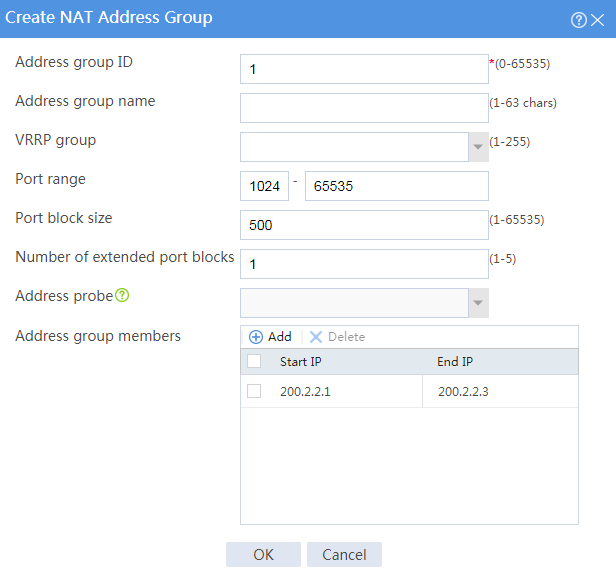
4. Configure a NAT address group.
# On the top navigation bar, click Policies.
# From the navigation pane, select NAT > NAT Advanced Settings > NAT Address Groups.
# Click Create.
# Create a NAT address group, as shown in Figure 6.
Figure 6 Creating a NAT address group
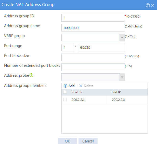
# Click OK.
5. Configure an outbound dynamic NAT rule.
# On the top navigation bar, click Policies.
# From the navigation pane, select NAT > Dynamic NAT.
# On the Outbound Dynamic NAT (Object Group-Based) tab, click Create.
# Create an outbound dynamic NAT rule, as shown in Figure 7.
Figure 7 Creating an outbound dynamic NAT rule
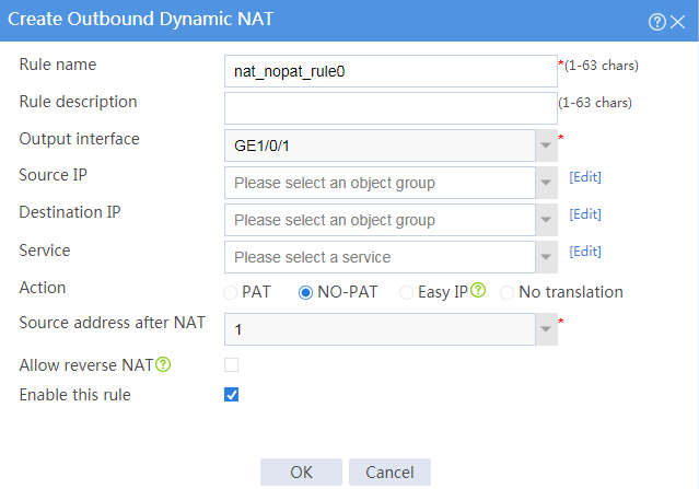
# Click OK.
Verifying the configuration
1. Verify that the host can successfully ping the server on the external network.
C:\Users\abc>ping 100.100.100.100
Pinging host.com [100.100.100.100] with 32 bytes of data:
Reply from 100.100.100.100: bytes=32 time<1ms TTL=253
Reply from 100.100.100.100: bytes=32 time<1ms TTL=253
Reply from 100.100.100.100: bytes=32 time<1ms TTL=253
Reply from 100.100.100.100: bytes=32 time<1ms TTL=253
Ping statistics for 100.100.100.100:
Packets: Sent = 4, Received = 4, Lost = 0 (0% loss),
Approximate round trip times in milli-seconds:
Minimum = 0ms, Maximum = 0ms, Average = 0ms
2. Verify that a NAT session is generated when the host accesses the server.
# On the top navigation bar, click Monitor.
# From the navigation pane, select Sessions.
Figure 8 Session list

Example: Configuring PAT for dynamic NAT
Network configuration
As shown in Figure 9, a company has only one public IP addresses 200.2.2.1/24. Configure PAT for outbound dynamic NAT to allow only internal hosts to access the Internet by using this public IP address.

Software versions used
This configuration example was created and verified on F9345 of the F1060 device.
Procedure
1. Assign IP addresses to interfaces and add the interfaces to security zones.
# On the top navigation bar, click Network.
# From the navigation pane, select Interface Configuration > Interfaces.
# Click the Edit icon for GE 1/0/1.
# In the dialog box that opens, configure the interface:
a. Select the Untrust security zone.
b. On the IPv4 Address tab, enter the IP address and mask of the interface. In this example, enter 200.2.2.254/24.
c. Click OK.
# Add GE 1/0/2 to the Trust security zone and set its IP address to 172.16.100.254/24 in the same way you configure GE 1/0/1.
2. Configure settings for routing.
This example configures a static route. If dynamic routes are required, configure a dynamic routing protocol.
# On the top navigation bar, click Network.
# From the navigation pane, select Routing > Static Routing.
# On the IPv4 Static Routing tab, click Create.
# In the dialog box that opens, configure a static route to permit packets from the hosts to the server:
a. Specify the IP address of the server as the destination IP. In this example, the address is 100.100.100.100.
b. Enter the mask length. In this example, enter 24.
c. Specify the next-hop address as 200.2.2.253.
d. Click OK.
3. Configure a security policy.
# On the top navigation bar, click Policies.
# From the navigation pane, select Security Policies > Security Policies.
# Click Create and click Create a policy.
# In the dialog box that opens, configure policy parameters as follows:
a. Enter a policy name. In this example, the name is Secpolicy.
b. Select the source zone. In this example, the source zone is Trust.
c. Select the destination zone. In this example, the destination zone is Untrust.
d. Select IPv4 as the type.
e. Select Permit as the action.
f. Specify the IP addresses of the hosts as the source IPv4 addresses. In this example, the address are 172.16.100.1, 172.16.100.2, and 172.16.100.3.
g. Specify the IP address of the server as the destination IPv4 address. In this example, the address is 100.100.100.100.
h. Click OK.
4. Configure a NAT address group.
# On the top navigation bar, click Policies.
# From the navigation pane, select NAT > NAT Advanced Settings > NAT Address Groups.
# Click Create.
# Create a NAT address group, as shown in Figure 10.
Figure 10 Creating a NAT address group
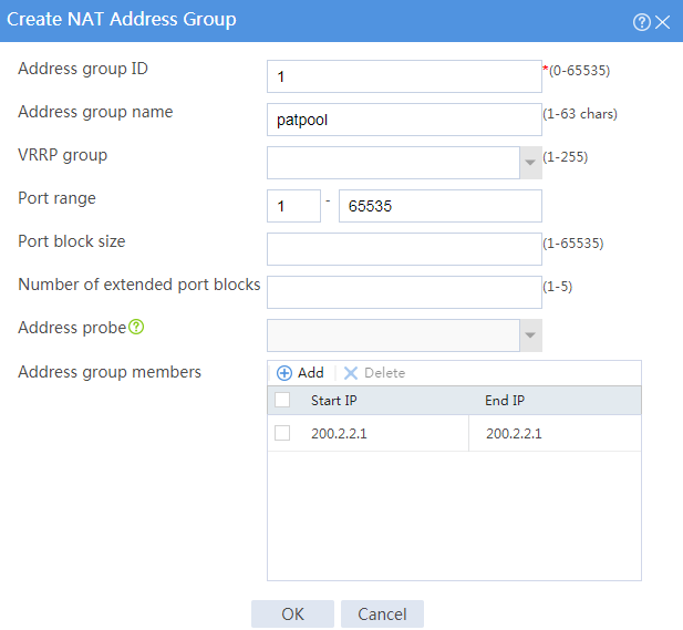
# Click OK.
5. Configure an outbound dynamic NAT rule.
# On the top navigation bar, click Policies.
# From the navigation pane, select NAT > Dynamic NAT.
# On the Outbound Dynamic NAT (Object Group-Based) tab, click Create.
# Create an outbound dynamic NAT rule, as shown in Figure 11.
Figure 11 Creating an outbound dynamic NAT rule
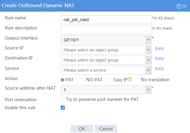
# Click OK.
Verifying the configuration
1. Verify that the host can successfully ping the server on the external network.
C:\Users\abc>ping 100.100.100.100
Pinging host.com [100.100.100.100] with 32 bytes of data:
Reply from 100.100.100.100: bytes=32 time<1ms TTL=253
Reply from 100.100.100.100: bytes=32 time<1ms TTL=253
Reply from 100.100.100.100: bytes=32 time<1ms TTL=253
Reply from 100.100.100.100: bytes=32 time<1ms TTL=253
Ping statistics for 100.100.100.100:
Packets: Sent = 4, Received = 4, Lost = 0 (0% loss),
Approximate round trip times in milli-seconds:
Minimum = 0ms, Maximum = 0ms, Average = 0ms
2. Verify that a NAT session is generated when the host accesses the server.
# On the top navigation bar, click Monitor.
# From the navigation pane, select Sessions.
Figure 12 Session list
Example: Configuring the NAT Server
Network configuration
As shown in Figure 13, the server in the internal network to provide Web services for external users.
Configure the NAT Server feature to allow the external user to use public address 200.2.2.1/24 to access the internal server.
Software versions used
This configuration example was created and verified on F9345 of the F1060 device.
Procedure
1. Assign IP addresses to interfaces and add the interfaces to security zones.
# On the top navigation bar, click Network.
# From the navigation pane, select Interface Configuration > Interfaces.
# Click the Edit icon for GE 1/0/1.
# In the dialog box that opens, configure the interface:
a. Select the Untrust security zone.
b. On the IPv4 Address tab, enter the IP address and mask of the interface. In this example, enter 200.2.2.254/24.
c. Click OK.
# Add GE 1/0/2 to the Trust security zone and set its IP address to 172.16.100.254/24 in the same way you configure GE 1/0/1.
2. Configure a security policy.
# On the top navigation bar, click Policies.
# From the navigation pane, select Security Policies > Security Policies.
# Click Create and click Create a policy.
# In the dialog box that opens, configure policy parameters as follows:
a. Enter a policy name. In this example, the name is Secpolicy.
b. Select the source zone. In this example, the source zone is Untrust.
c. Select the destination zone. In this example, the destination zone is Trust.
d. Select IPv4 as the type.
e. Select Permit as the action.
f. Specify the IP address of the host as the source IPv4 address. In this example, the address is 100.100.100.100.
g. Specify the IP address of the server as the destination IPv4 address. In this example, the address is 172.16.100.1.
h. Click OK.
3. Configure a NAT server rule.
# On the top navigation bar, click Policies.
# From the navigation pane, select NAT > NAT Servers > Policy Configuration.
# Click Create.
# Create a NAT server rule, as shown in Figure 14.
Figure 14 Creating a NAT server rule
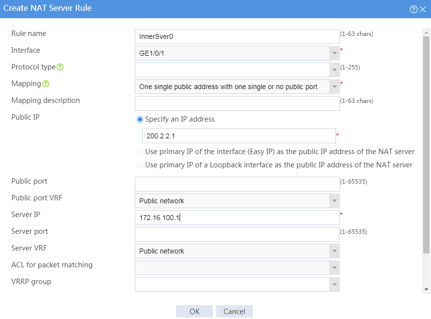
# Click OK.
Verifying the configuration
1. Verify that the host can successfully ping the public address.
C:\Users\abc>ping 200.2.2.1
Pinging host.com [200.2.2.1] with 32 bytes of data:
Reply from 200.2.2.1: bytes=32 time<1ms TTL=253
Reply from 200.2.2.1: bytes=32 time<1ms TTL=253
Reply from 200.2.2.1: bytes=32 time<1ms TTL=253
Reply from 200.2.2.1: bytes=32 time<1ms TTL=253
Ping statistics for 200.2.2.1:
Packets: Sent = 4, Received = 4, Lost = 0 (0% loss),
Approximate round trip times in milli-seconds:
Minimum = 0ms, Maximum = 0ms, Average = 0ms
2. Verify that a NAT session is generated when the host accesses the internal server.
# On the top navigation bar, click Monitor.
# From the navigation pane, select Sessions.
Figure 15 Session list

Example: Configuring static NAT444
Network configuration
As shown in Figure 16, a company has one public IP address 200.2.2.1/24. Configure static NAT444 port block mapping to allow internal network users to use this public IP address to access the Internet. Configure the port range as 10001 to 15000, and set the port block size to 500.

Software versions used
This configuration example was created and verified on F9345 of the F1060 device.
Procedure
1. Assign IP addresses to interfaces and add the interfaces to security zones.
# On the top navigation bar, click Network.
# From the navigation pane, select Interface Configuration > Interfaces.
# Click the Edit icon for GE 1/0/1.
# In the dialog box that opens, configure the interface:
a. Select the Untrust security zone.
b. On the IPv4 Address tab, enter the IP address and mask of the interface. In this example, enter 200.2.2.254/24.
c. Click OK.
# Add GE 1/0/2 to the Trust security zone and set its IP address to 172.16.100.254/24 in the same way you configure GE 1/0/1.
2. Configure settings for routing.
This example configures a static route. If dynamic routes are required, configure a dynamic routing protocol.
# On the top navigation bar, click Network.
# From the navigation pane, select Routing > Static Routing.
# On the IPv4 Static Routing tab, click Create.
# In the dialog box that opens, configure a static route to permit packets from the hosts to the server:
a. Specify the IP address of the server as the destination IP address. In this example, the address is 100.100.100.100.
b. Enter the mask length. In this example, enter 24.
c. Specify the public address as the next-hop address as 200.2.2.253.
d. Click OK.
3. Configure a security policy.
# On the top navigation bar, click Policies.
# From the navigation pane, select Security Policies > Security Policies.
# Click Create and click Create a policy.
# In the dialog box that opens, configure policy parameters as follows:
a. Enter a policy name. In this example, the name is Secpolicy.
b. Select the source zone. In this example, the source zone is Trust.
c. Select the destination zone. In this example, the destination zone is Untrust.
d. Select IPv4 as the type.
e. Select Permit as the action.
f. Specify the IP addresses of the hosts as the source IPv4 addresses. In this example, the address are 172.16.100.1, 172.16.100.2, and 172.16.100.3.
g. Specify the IP address of the server as the destination IPv4 address. In this example, the address is 100.100.100.100.
h. Click OK.
4. Configure a port block group.
# On the top navigation bar, click Policies.
# From the navigation pane, select NAT > Static NAT444 > Port Blocks.
# Click Create.
# Create a port block group, as shown in Figure 17.
Figure 17 Creating a port block group
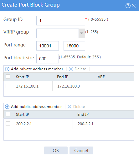
# Click OK.
5. Configure a static NAT444 rule.
# On the top navigation bar, click Policies.
# From the navigation pane, select NAT > Static NAT444 > Policy Configuration.
# Click Create.
# Create a static NAT444 rule, as shown in Figure 18.
Figure 18 Creating a static NAT444 rule
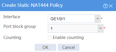
# Click OK.
Verifying the configuration
1. Verify that the host can successfully ping the server on the external network.
C:\Users\abc>ping 100.100.100.100
Pinging host.com [100.100.100.100] with 32 bytes of data:
Reply from 100.100.100.100: bytes=32 time<1ms TTL=253
Reply from 100.100.100.100: bytes=32 time<1ms TTL=253
Reply from 100.100.100.100: bytes=32 time<1ms TTL=253
Reply from 100.100.100.100: bytes=32 time<1ms TTL=253
Ping statistics for 100.100.100.100:
Packets: Sent = 4, Received = 4, Lost = 0 (0% loss),
Approximate round trip times in milli-seconds:
Minimum = 0ms, Maximum = 0ms, Average = 0ms
2. Verify that a NAT session is generated when the host accesses the server.
# On the top navigation bar, click Monitor.
# From the navigation pane, select Sessions.
Figure 19 Session list

Example: Configuring dynamic NAT444
Network configuration
As shown in Figure 20, a company has public IP addresses 200.2.2.1/24 to 200.2.2.3/24. Configure NAT444 dynamic port block mapping to meet the following requirements:
· The internal network users can use public IP addresses to access the Internet.
· The port range for the public IP addresses is 1024 to 65535.
· The port block size is 500.
· If the ports in the assigned port block are all used, extend another port block for users.

Software versions used
This configuration example was created and verified on F9345 of the F1060 device.
Procedure
1. Assign IP addresses to interfaces and add the interfaces to security zones.
# On the top navigation bar, click Network.
# From the navigation pane, select Interface Configuration > Interfaces.
# Click the Edit icon for GE 1/0/1.
# In the dialog box that opens, configure the interface:
a. Select the Untrust security zone.
b. On the IPv4 Address tab, enter the IP address and mask of the interface. In this example, enter 200.2.2.254/24.
c. Click OK.
# Add GE 1/0/2 to the Trust security zone and set its IP address to 172.16.100.254/24 in the same way you configure GE 1/0/1.
2. Configure settings for routing.
This example configures a static route. If dynamic routes are required, configure a dynamic routing protocol.
# On the top navigation bar, click Network.
# From the navigation pane, select Routing > Static Routing.
# On the IPv4 Static Routing tab, click Create.
# In the dialog box that opens, configure a static route to permit packets from the hosts to the server:
a. Specify the IP address of the server as the destination IP. In this example, the address is 100.100.100.100.
b. Enter the mask length. In this example, enter 24.
c. Specify the public address as the next-hop address as 200.2.2.253.
d. Click OK.
3. Configure a security policy.
# On the top navigation bar, click Policies.
# From the navigation pane, select Security Policies > Security Policies.
# Click Create and click Create a policy.
# In the dialog box that opens, configure policy parameters as follows:
a. Specify the policy name. In this example, the name is Secpolicy.
b. Select the source zone. In this example, the source zone is Trust.
c. Select the destination zone. In this example, the destination zone is Untrust.
d. Select IPv4 as the type.
e. Select Permit as the action.
f. Specify the IP addresses of the host as the source IPv4 addresses. In this example, the address is 172.16.100.1, 172.16.100.2, and 172.16.100.3.
g. Specify the IP address of the server as the destination IPv4 address. In this example, the address is 100.100.100.100.
h. Click OK.
4. Configure a security policy.
# On the top navigation bar, click Policies.
# From the navigation pane, select Security Policies > Security Policies.
# Click Create.
# Create a security policy to allow packets to pass through.
5. Configure a NAT address group.
# On the top navigation bar, click Policies.
# From the navigation pane, select NAT > NAT Advanced Settings > NAT Address Groups.
# Click Create.
# Create a NAT address group, as shown in Figure 21.
Figure 21 Creating a NAT address group
# Click OK.
6. Configure an outbound dynamic NAT444 rule.
# On the top navigation bar, click Policies.
# From the navigation pane, select NAT > Dynamic NAT444.
# On the Outbound Dynamic NAT444 (Object Group-Based) tab, click Create.
# Create an outbound dynamic NAT444 rule, as shown in Figure 22.
Figure 22 Configuring a dynamic NAT444 rule
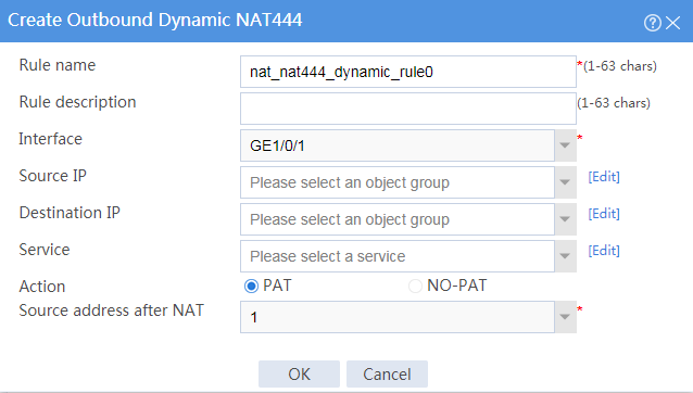
# Click OK.
Verifying the configuration
1. Verify that the host can successfully ping the server on the external network.
C:\Users\abc>ping 100.100.100.100
Pinging host.com [100.100.100.100] with 32 bytes of data:
Reply from 100.100.100.100: bytes=32 time<1ms TTL=253
Reply from 100.100.100.100: bytes=32 time<1ms TTL=253
Reply from 100.100.100.100: bytes=32 time<1ms TTL=253
Reply from 100.100.100.100: bytes=32 time<1ms TTL=253
Ping statistics for 100.100.100.100:
Packets: Sent = 4, Received = 4, Lost = 0 (0% loss),
Approximate round trip times in milli-seconds:
Minimum = 0ms, Maximum = 0ms, Average = 0ms
2. Verify that a NAT session is generated when the host accesses the server.
# On the top navigation bar, click Monitor.
# From the navigation pane, select Sessions.
Figure 23 Session list
